1
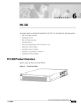
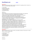
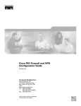
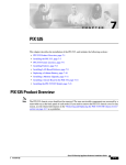
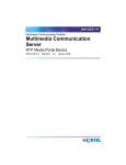
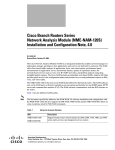
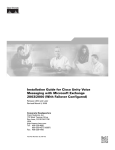
C H A P T E R
2
Installing a PIX Firewall
The following sections in this chapter describe how to install a PIX Firewall:
•
Installation Overview
•
Before You Begin the Installation
•
Installing a PIX 506
•
Installing a PIX 515
•
Installing a PIX 525
•
Installing a PIX 520 or Earlier Model
•
Startup Messages
•
Software Installation Notes
Installation Overview
Follow these steps to install a PIX Firewall:
Note
Step 1
If your PIX Firewall model supports a failover configuration, perform the steps that follow
only on the Primary (Active) unit. Refer to Chapter 3, “Installing Failover” for
information about setting up a failover configuration. (Does not apply to the PIX 506.)
Review the safety precautions outlined in the Regulatory Compliance and Safety Information for the
Cisco Secure PIX Firewall Version 5.2 document. You can view this online at the following site:
http://www.cisco.com/univercd/cc/td/doc/product/iaabu/pix/pix_v52/pixrcs52.htm
Step 2
Completely read the release notes for your respective software version referenced in the section
“Related Documentation” in “About This Manual.”
Step 3
Unpack the PIX Firewall. The PIX Firewall consists of two main components, the PIX Firewall unit and
a separate accessory kit. The accessory kit contains documentation, a power supply or cord, rack
mounting hardware (not applicable to the PIX 506), and additional software you can use with your
PIX Firewall.
Step 4
Place the PIX Firewall on a stable work surface.
Step 5
If you need to download software, refer to the “Software Installation Notes” section.
Installation Guide for the Cisco Secure PIX Firewall Version 5.2
78-11180-01
2-1
Chapter 2
Installing a PIX Firewall
Before You Begin the Installation
Before You Begin the Installation
Note
The information you gather here is required during configuration and is a reminder to find
it while installing your PIX Firewall—before beginning the configuration. You can use
this information with Chapter 9, “Installing the PIX Firewall Setup Wizard” or with the
Cisco PIX Firewall Configuration Guide, Version 5.2.
Before you begin the installation, gather information about each network interface that will be
connected to the PIX Firewall. If you have a PIX 506, all you need are IP addresses for the two
interfaces. All other information in Table 2-1 will be provided automatically in the configuration that
comes with the PIX 506. For models other than the PIX 506, locate the following information before
proceeding.
Table 2-1
Configuration Information
Outside
Network
Inside
Network
Perimeter 1 Perimeter 2 Perimeter 3 Perimeter 4
Interface Speed
IP Address and
Netmask
Interface Name—HW
Interface Name—SW
Security Level
MTU Size
To prepare to configure the PIX Firewall, locate the following information:
•
Interface speed—The speed of each network interface. You only need to specify a value for
Ethernet interface boards that do not autosense the interface’s speed, connection type, and full/half
duplex support; or for Token Ring interface boards. Use the interface command to enter the speed
for each interface in the configuration.
•
IP address and netmask—The IP address and network mask for each network interface. The
IP address for each interface must be different from any others you use in your network. Use the ip
address command to enter the IP address and network mask for each interface in the configuration.
•
Interface name—HW—The hardware name for the interface, such as ethernet0, ethernet1, token0,
token1, fddi0, fddi1, and so on. Use the nameif command to enter the hardware name for the
interface in the configuration.
•
Interface name—SW—The software name for the interface, such as inside or outside. The inside
interface must be named “inside.” All other interfaces can have any name. Note that you will need
to enter this name frequently in the configuration. Use the nameif command to associate the
hardware and software names in the configuration.
•
Security level—Used to determine the level of trust for each network interface. The outside
network must have a security level of 0 and the inside network must be 100. The perimeter
interfaces can be any value from 1 to 99. Use the nameif command to enter the security level in the
configuration.
Installation Guide for the Cisco Secure PIX Firewall Version 5.2
2-2
78-11180-01
Chapter 2
Installing a PIX Firewall
Installing a PIX 506
•
MTU size—The maximum transmission unit (MTU) size for each network interface. You only need
to specify a value if you want to set an MTU size that differs from the default
(1,500 bytes/block for Ethernet; 8,192 bytes/block for Token Ring and FDDI).
In addition, you should determine the IP address of the outside default router and your network topology
and security policy. We recommend that you take a few minutes to draw a diagram of your network with
IP addresses, indicating which computers you are protecting, and which switches, routers, and hosts are
on each network.
Installing a PIX 506
This section includes the following topics:
•
Introduction
•
PIX 506 Installation Steps
•
Configuring the PIX 506
Introduction
To download software to a PIX Firewall, see the “Software Installation Notes” section in this chapter
or refer to the Cisco PIX Firewall Configuration Guide, Version 5.2.
The Front Panel LEDs, as shown in Figure 2-1, are as follows:
•
POWER—On when the unit has power.
•
ACT—Active indicator—On when the software image has been loaded on the PIX 506 unit.
•
NETWORK—On when at least one network interface is passing traffic.
Figure 2-1
ACT
NETWORK
25735
POWER
PIX 506 Front Panel LEDs
PIX 506 back panel connectors and LEDS are shown Figure 2-2.
The LEDs for the RJ-45 network ports display the following transmission states:
•
ACT—Shows network activity.
•
LINK—Shows that data is passing on the network to which the connector is attached.
The USB port to the left of the Console port is not used.
Installation Guide for the Cisco Secure PIX Firewall Version 5.2
78-11180-01
2-3
Chapter 2
Installing a PIX Firewall
Installing a PIX 506
Figure 2-2
PIX 506 Back Panel
ACT(ivity)
LED
ACT(ivity)
LED
LINK
LINK
LED
LED
Power switch
DC
POWER
INPUT
LINK
ACT
ETHERNET 1
LINK
ETHERNET 0
10BaseT
(RJ-45)
USB
38852
ACT
CONSOLE
10BaseT USB
(RJ-45) port
Console
port (RJ-45)
PIX 506 Installation Steps
The PIX 506 should be placed on a flat, stable surface. The PIX 506 is not rack mountable.
Follow these steps to install a PIX 506:
Step 1
Use the RJ-45 Console port to connect a computer to enter configuration commands. Locate the serial
cable from the accessory kit. The serial cable assembly consists of a null modem cable with RJ-45
connectors, and one DB-9 connector and a DB-25 connector. Connect the cable as shown in Figure 2-3
so that you have either a DB-9 or DB-25 connector on one end as required by the serial port for your
computer, and the other end is the RJ-45 connector.
Connect the RJ-45 connector to the PIX 506 and connect the other end to the serial port connector on
your computer.
Figure 2-3
PIX 506 Serial Console Cable
DC
POWER
INPUT
LINK
ETHERNET 1
ACT
LINK
ETHERNET 0
USB
CONSOLE
Console
port (RJ-45)
RJ-45 to
DB-9 or DB-25
serial cable
(null-modem)
Computer serial port
DB-9 or DB-25
38853
ACT
Installation Guide for the Cisco Secure PIX Firewall Version 5.2
2-4
78-11180-01
Chapter 2
Installing a PIX Firewall
Installing a PIX 506
Step 2
The inside or outside network connections can be made to either interface port on the PIX 506. Connect
the inside network cable to the interface connector marked ETHERNET 0 or ETHERNET 1. Connect
the outside network cable to the remaining Ethernet port. Refer to the “Configuring the PIX 506”
section for information on how to configure the ports.
Step 3
The PIX 506 uses an external AC to DC power supply. Power is supplied to the PIX 506 by connecting
the power supply to the back of the PIX 506 and connecting a separate AC power cord to the power
supply. Figure 2-4 displays the cable connection from the power supply to the PIX 506, and displays
the AC power cord connector (at the opposite end of the power supply).
Figure 2-4
Connecting the Power Supply Module to the PIX 506
DC
POWER
INPUT
LINK
ETHERNET 1
ACT
LINK
ETHERNET 0
USB
CONSOLE
38854
ACT
Power supply
Step 4
When you are ready to start the PIX 506, power on the unit from the switch at the rear of the unit.
Configuring the PIX 506
If needed, you can use the PFSS (PIX Firewall Syslog Server) with the PIX 506. Refer to Chapter 4,
“Installing the PIX Firewall Syslog Server (PFSS),” for more information on the installation and use of
PFSS.
The PIX Firewall Setup Wizard provides an easy-to-use interface for building the initial PIX Firewall
configuration. For more information on the PIX Firewall Setup Wizard, see Chapter 9, “Installing the
PIX Firewall Setup Wizard.”
For more configuration information, refer to the Cisco PIX Firewall Configuration Guide, Version 5.2,
which is available in your accessory kit or online at the following site:
http://www.cisco.com/en/US/products/sw/secursw/ps2120/products_configuration_guide_book09186
a00801027d5.html
Always check the release notes first before configuring the PIX Firewall for the latest release details.
This document is also in your accessory kit or you can view it online at the following site:
http://www.cisco.com/en/US/products/sw/secursw/ps2120/prod_release_notes_list.html
Installation Guide for the Cisco Secure PIX Firewall Version 5.2
78-11180-01
2-5
Chapter 2
Installing a PIX Firewall
Installing a PIX 515
Installing a PIX 515
This section includes the following topics:
•
Introduction
•
Mounting the PIX 515
•
PIX 515 Installation Steps
•
Configuring the PIX 515
•
PIX 515 Feature Licenses
Introduction
To download software to a PIX Firewall, see the “Software Installation Notes” section in this chapter
or refer to the Cisco PIX Firewall Configuration Guide, Version 5.2.
The PIX 515 front panel LEDs are as follows (see Figure 2-5):
•
POWER—On when the unit has power.
•
ACT—On when the unit is the Active failover unit. If failover is not enabled, this light is on. If
failover is present, the light is on when the unit is the Active unit and off when the unit is in Standby
mode.
•
NETWORK—On when at least one network interface is passing traffic.
Figure 2-5
ACT
NETWORK
25735
POWER
PIX 515 Front Panel LEDs
Installation Guide for the Cisco Secure PIX Firewall Version 5.2
2-6
78-11180-01
Chapter 2
Installing a PIX Firewall
Installing a PIX 515
Refer to Figure 2-6 for a display of the controls and connectors on the PIX 515 back panel.
Figure 2-6
PIX 515 Features
100 Mbps
LED
LINK
LED
100 Mbps
LED
FDX LINK
LED LED
FDX
LED
PIX-515
DO NOT INSTALL INTERFACE
CARDS WITH POWER APPLIED
FDX
10/100 ETHERNET 1
10/100BaseTX
ETHERNET 1
(RJ-45)
100 Mbps Link
FAILOVER
FDX
10/100 ETHERNET 0
CONSOLE
24298
100 Mbps Link
10/100BaseTX
Console Power switch
ETHERNET 0 port (RJ-45)
(RJ-45)
The LEDs for the network ports display the following transmission states:
•
100 Mbps—100 megabits per second 100BaseTX communication. If the light is off, that port is
using 10 megabits per second data exchange.
•
LINK—Shows that data is passing on the network to which the connector is attached.
•
FDX—Shows that the connection uses full-duplex data exchange where data can be transmitted and
received simultaneously. If this light is off, half-duplex is in effect.
The inside or outside network connections can be made to any available interface port on the PIX 515.
If you are only using the ETHERNET 0 and ETHERNET 1 ports, connect the inside network cable to
the interface connector marked ETHERNET 0 or ETHERNET 1. Connect the outside network cable to
the remaining Ethernet port. Refer to “Configuring the PIX 515” for information on how to configure
the ports.
The USB port to the left of the Console port is not used. The detachable plate above the ETHERNET 1
connector is also not used.
Installation Guide for the Cisco Secure PIX Firewall Version 5.2
78-11180-01
2-7
Chapter 2
Installing a PIX Firewall
Installing a PIX 515
Mounting the PIX 515
The PIX 515 can be mounted in a rack, on a wall, or on a flat surface.
If you do not wish to rack mount the unit, attach the rubber feet to the bottom of the unit as shown in
Figure 2-7.
Figure 2-7
Attaching the Rubber Feet to the PIX 515
24301
Fan
Unused
Rack Mounting
Observe the following before installing the PIX 515 into an equipment rack:
•
If you wish to install optional circuit boards or memory, you can install the brackets on the unit for
rack mounting, but do not put the PIX 515 in the equipment rack until you have installed the new
boards. The top panel of the PIX 515 must be removed to properly install or remove a circuit board.
Refer to Chapter 5, “Opening a PIX Firewall Chassis” for information on how to remove the chassis
top panel.
– For more information on installing circuit boards, see Chapter 7, “Installing a Circuit Board.”
– If you need to install additional memory, refer to Chapter 6, “Installing a Memory Upgrade.”
Use the following steps to install the PIX 515 in a rack:
Step 1
Attach the bracket to the unit using the supplied screws. You can attach the brackets to the holes near
the front of the unit.
Step 2
Attach the unit to the equipment rack.
Installation Guide for the Cisco Secure PIX Firewall Version 5.2
2-8
78-11180-01
Chapter 2
Installing a PIX Firewall
Installing a PIX 515
Vertical Mounting
To mount the PIX 515 vertically, attach the brackets to the side of the unit and mount the unit vertically
as shown in Figure 2-8.
Figure 2-8
Installing the PIX 515 Vertically
FDX
100 Mbps Link
FDX
24303
10/100 ETHERNET 0/0
100 Mbps Link
DO NOT INSTALL INTERFACE
CARDS WITH POWER APPLIED
10/100 ETHERNET 0/0
CONSOLE
FAILOVER
PIX-515
PIX 515 Installation Steps
Use the following steps to install a PIX 515:
Step 1
Use the Console port to connect to a computer to enter configuration commands. Locate the serial cable
from the accessory kit. The serial cable assembly consists of a null modem cable with RJ-45 connectors,
and one DB-9 connector and a DB-25 connector. Connect the cable as shown in Figure 2-9 so that you
have either a DB-9 or DB-25 connector on one end as required by the serial port for your computer, and
the other end is the RJ-45 connector.
Connect the RJ-45 connector to the PIX 515 Console port and connect the other end to the serial port
connector on your computer.
Installation Guide for the Cisco Secure PIX Firewall Version 5.2
78-11180-01
2-9
Chapter 2
Installing a PIX Firewall
Installing a PIX 515
PIX 515 Serial Console Cable
PIX-515
Figure 2-9
100 Mbps Link
FAILOVER
FDX
10/100 ETHERNET 0
CONSOLE
Computer serial port
DB-9 or DB-25
Console
port (RJ-45)
Step 2
29226
RJ-45 to
DB-9 or DB-25
serial cable
(null-modem)
If your unit has a four-port Ethernet card already installed, refer to Figure 2-10. (The four-port interface
card requires the PIX-515-UR license to be accessed.) If it has one or two single-port cards, refer to
Figure 2-11. If you need to install an optional circuit board such as a Private Link board, single-port
Ethernet board, FDDI board, or a four-port Ethernet board, refer to Chapter 5, “Opening a PIX Firewall
Chassis” for information about how to open the top panel of the chassis to install circuit boards.
Figure 2-10 Four-Port Ethernet Connectors in a PIX 515
25733
Ethernet 5
Ethernet 3
100 Mbps Link
PIX-515
DO NOT INSTALL INTERFACE
CARDS WITH POWER APPLIED
FDX
10/100 ETHERNET 1
Ethernet 2
Ethernet 4
100 Mbps Link
FAILOVER
FDX
10/100 ETHERNET 0
CONSOLE
Ethernet 1
Ethernet 0
Connect the inside, outside, or perimeter network cables to the interface ports. Starting from the top left
the connectors are Ethernet 2, Ethernet 3, Ethernet 4, and Ethernet 5. The maximum number of allowed
interfaces is 6; do not add a single-port card in the extra slot below the four-port card.
Figure 2-11 Two Single-Port Ethernet Connectors in a PIX 515
25734
Ethernet 2
100 Mbps Link
PIX-515
DO NOT INSTALL INTERFACE
CARDS WITH POWER APPLIED
FDX
10/100 ETHERNET 1
Ethernet 3
100 Mbps Link
FAILOVER
FDX
10/100 ETHERNET 0
CONSOLE
Ethernet 1
Ethernet 0
Installation Guide for the Cisco Secure PIX Firewall Version 5.2
2-10
78-11180-01
Chapter 2
Installing a PIX Firewall
Installing a PIX 515
As shown in Figure 2-11, if your unit has one or two single-port Ethernet cards installed in the auxiliary
assembly on the left of the unit at the rear, the cards are numbered top to bottom so that the top card is
Ethernet 2 and the bottom card is Ethernet 3. (Additional interface cards require the PIX-515-UR
license to be accessed.)
Step 3
Note
Step 4
If you have a second PIX Firewall to use as a failover unit, install the failover feature and cable as
described in Chapter 3, “Installing Failover.”
Do not power on the failover units until the primary unit has been configured.
When you are ready to start the PIX 515, power on the unit from the switch at the rear of the unit.
Configuring the PIX 515
The PIX Firewall Setup Wizard provides an easy-to-use interface for building the initial PIX Firewall
configuration. For more information on the PIX Firewall Setup Wizard, see Chapter 9, “Installing the
PIX Firewall Setup Wizard.”
For more configuration information, refer to the Cisco PIX Firewall Configuration Guide, Version 5.2,
which is available in your accessory kit or online at the following site:
http://www.cisco.com/en/US/products/sw/secursw/ps2120/products_configuration_guide_book09186
a00801027d5.html
Always check the release notes first before configuring the PIX Firewall for the latest release details.
This document is also in your accessory kit or you can view it online at the following site:
http://www.cisco.com/en/US/products/sw/secursw/ps2120/prod_release_notes_list.html
Refer to the next section for feature license options.
PIX 515 Feature Licenses
If you have a PIX-515-UR unrestricted feature license, the following options are available:
Note
•
If you have a second PIX 515 to use as a failover unit, install the failover feature and cable as
described in Chapter 3, “Installing Failover.”
•
If needed, install the PIX Firewall Syslog Server as described in Chapter 4, “Installing the PIX
Firewall Syslog Server (PFSS).”
•
If you need to install an optional circuit board such as a Private Link board, single-port Ethernet
board, FDDI board, or a four-port Ethernet board, refer to Chapter 5, “Opening a PIX Firewall
Chassis” for information about how to open the top panel of the chassis to install circuit boards.
It is very important to open the top panel before installing circuit boards in the PIX 515.
Even though it may appear possible to add or remove cards from the back panel, removing
the top panel greatly simplifies the process.
•
If you need to install additional memory, refer to Chapter 6, “Installing a Memory Upgrade.”
Installation Guide for the Cisco Secure PIX Firewall Version 5.2
78-11180-01
2-11
Chapter 2
Installing a PIX Firewall
Installing a PIX 525
Note
If for any reason you may choose to downgrade to any software version, note that you need
to use the clear flashfs command before doing so. A new section has been added to Flash
memory that must be cleared before downgrading.
Installing a PIX 525
This section includes the following topics:
•
Introduction
•
PIX 525 Installation Steps
•
Configuring the PIX 525
•
PIX 525 Feature Licenses
Introduction
To download software to a PIX Firewall, see the “Software Installation Notes” section in this chapter
or refer to the Cisco PIX Firewall Configuration Guide, Version 5.2.
The PIX 525 is displayed in Figure 2-12.
44009
Figure 2-12 PIX 525
CISCO SECURITY PIX
525 SERIES
F I R E W A L L
POWER
ACTIVE
The rear panel of the PIX 525 is shown in Figure 2-13.
44010
Figure 2-13 PIX 525 Rear Panel View
F
A
I
L
O
V
E
R
100Mbps ACT
LINK
10/100 ETHERNET 1
100Mbps ACT
PIX-525
LINK
10/100 ETHERNET 0
USB
CONSOLE
There are two LEDs on the front panel of the PIX 525 (see Figure 2-14). The LEDs function as follows:
•
POWER—On when the unit has power.
Installation Guide for the Cisco Secure PIX Firewall Version 5.2
2-12
78-11180-01
Chapter 2
Installing a PIX Firewall
Installing a PIX 525
•
ACT—On when the unit is the Active failover unit. If failover is present, the light is on when the
unit is the Active unit and off when the unit is in Standby mode.
44568
Figure 2-14 PIX 525 Front Panel LEDs
There are three LEDs for the each RJ-45 interface port and three types of fixed interface connectors on
the back of the PIX 525. The LEDs and connectors are shown in Figure 2-15.
Figure 2-15 PIX 525 Rear Panel
ACT(ivity)
ACT(ivity)
LED
LED
100Mbps
LINK
LINK
LED
LED
LED
Failover
connector
F
A
I
L
O
V
E
R
LINK
10/100 ETHERNET 1
100Mbps ACT
PIX-525
LINK
10/100 ETHERNET 0
USB
CONSOLE
44567
100Mbps ACT
10/100 BaseTX
USB
Ethernet 1
port
(RJ-45)
10/100 BaseTX
Console
Ethernet 0
port (RJ-45)
(RJ-45)
The LEDs display the following transmission states:
•
100 Mbps—100 megabits per second 100BaseTX communication. If the light is off during network
activity, that port is using 10 megabits per second data exchange.
•
ACT—Shows network activity.
Installation Guide for the Cisco Secure PIX Firewall Version 5.2
78-11180-01
2-13
Chapter 2
Installing a PIX Firewall
Installing a PIX 525
•
LINK—Shows that data is passing through that interface.
The following are fixed connectors on the back of the PIX 525:
•
RJ-45—Network and console connectors.
•
DB-15—Failover cable connector.
•
USB—Not used at the present time.
PIX 525 Installation Steps
Use the following steps to install a PIX 525:
Step 1
Step 2
The PIX 525 provides one set of brackets for installing the unit in an equipment rack. Use the following
steps if the unit is going to be installed into an equipment rack:
a.
Attach the brackets to the holes near the front of the unit on each side of the PIX 525 using the
supplied screws.
b.
Attach the unit to the equipment rack.
Use the Console port to connect a computer to enter configuration commands. Locate the serial cable
from the accessory kit. The serial cable assembly consists of a null modem cable with RJ-45 connectors,
and one DB-9 connector and a DB-25 connector. Connect the cable so that you have either a DB-9 or
DB-25 connector on one end as required by the serial port for your computer, and the other end is the
RJ-45 connector as shown in Figure 2-16.
Connect the RJ-45 serial cable connector to the PIX 525 console connector and connect the other end
to the serial port connector on your computer.
Figure 2-16 PIX 525 Rear Panel
F
A
I
L
O
V
E
R
LINK
10/100 ETHERNET 1
100Mbps ACT
PIX-525
LINK
10/100 ETHERNET 0
USB
CONSOLE
Console
port (RJ-45)
RJ-45 to
DB-9 or DB-25
serial cable
(null-modem)
Computer serial port
DB-9 or DB-25
44634
100Mbps ACT
Installation Guide for the Cisco Secure PIX Firewall Version 5.2
2-14
78-11180-01
Chapter 2
Installing a PIX Firewall
Installing a PIX 525
Step 3
The inside or outside network connections can be made to any available interface port on the PIX 525.
If you are only using the ETHERNET 0 and ETHERNET 1 ports, connect the inside network cable to
the interface connector marked ETHERNET 0 or ETHERNET 1. Connect the outside network cable to
the remaining Ethernet port. Refer to “Configuring the PIX 525” for information on how to configure
the ports.
Step 4
If you need to install an optional circuit board such as a Private Link, Token-Ring, FDDI, or Ethernet
type board, refer to Chapter 7, “Installing a Circuit Board.” If you need to install memory, use
Chapter 6, “Installing a Memory Upgrade,” for more information.
Note
It should not be necessary to remove the top panel of the PIX 525 to access the circuit
boards or memory. If you do need to open the top panel, refer to Chapter 5, “Opening a
PIX Firewall Chassis” for more information.
Step 5
Connect the network cables to the expansion interface ports. (The inside, outside, or perimeter network
connections can be made to any available interface port on the PIX 525.) The first expansion port
number, at the top left, is interface 2. Starting from that port and going from left to right and top to
bottom, the next port is interface 3, the next is interface 4, and so on. Use the “Configuring the PIX 525”
section for information on how to configure the ports.
Step 6
If you have a second PIX Firewall to use as a failover unit, install the failover feature and cable as
described in Chapter 3, “Installing Failover.”
Note
Step 7
Do not power on the failover units until the primary unit has been configured.
When you are ready to start the PIX 515, power on the unit from the switch at the rear of the unit.
Configuring the PIX 525
The PIX Firewall Setup Wizard provides an easy-to-use interface for building the initial PIX Firewall
configuration. For more information on the PIX Firewall Setup Wizard, see Chapter 9, “Installing the
PIX Firewall Setup Wizard.”
For more configuration information, refer to the Cisco PIX Firewall Configuration Guide, Version 5.2,
which is available in your accessory kit or online at the following site:
http://www.cisco.com/en/US/products/sw/secursw/ps2120/products_configuration_guide_book09186
a00801027d5.html
Always check the release notes first before configuring the PIX Firewall for the latest release details.
This document is also in your accessory kit or you can view it online at the following site:
http://www.cisco.com/en/US/products/sw/secursw/ps2120/prod_release_notes_list.html
Refer to the next section for feature license options.
Installation Guide for the Cisco Secure PIX Firewall Version 5.2
78-11180-01
2-15
Chapter 2
Installing a PIX Firewall
Installing a PIX 520 or Earlier Model
PIX 525 Feature Licenses
If you have a PIX-525-UR unrestricted feature license, the following options are available:
•
Note
Note
If you have a second PIX 525 to use as a failover unit, install the failover feature and cable as
described in Chapter 3, “Installing Failover.”
Do not power on the failover units until the primary unit has been configured.
•
If needed, install the PIX Firewall Syslog Server as described in Chapter 4, “Installing the PIX
Firewall Syslog Server (PFSS).”
•
If you need to install an optional circuit board such as a Private Link, Ethernet, FDDI, or
Token-Ring board, refer to Chapter 7, “Installing a Circuit Board.”
•
If you need to install additional memory, refer to Chapter 6, “Installing a Memory Upgrade.”
If for any reason you may choose to downgrade to any software version, note that you need
to use the clear flashfs command before doing so. A new section has been added to Flash
memory that must be cleared before downgrading.
Installing a PIX 520 or Earlier Model
The following topics are described in this section:
•
PIX 520 or Earlier Model Installation Instructions
•
PIX Firewall with a Four-Port Interface Card
•
Installing Interface Cables to a PIX 520 or Earlier Model
PIX 520 or Earlier Model Installation Instructions
Follow these steps to install a PIX 520 or earlier model:
Step 1
Refer to Figure 2-17 for information on the features of the PIX 520 unit.
Installation Guide for the Cisco Secure PIX Firewall Version 5.2
2-16
78-11180-01
Chapter 2
Installing a PIX Firewall
Installing a PIX 520 or Earlier Model
Figure 2-17 PIX 520 Front, Rear, and Side Panels.
Front
Rear
Power connector
Power switch
AC
PIX Firewall SERIES
RESET
Power
light
Reset
button
Auto-Range Selection
L:90-135V H:180-270V
Diskette
compartment
Power switch
Slots for
network
interfaces
Failover
connector
Console
connector
– +
DC
– +
DC power connector
Ground lugs
Fan duct
1 To access,
loosen screws
counterclockwise
4 To remove
diskette,
push button
Left side
Holes to connect
rackmount slide rails
(must be purchased
separately from
outside vendor)
Holes to connect
rackmount brackets
Rackmount
(if rackmounting
holes
is desired)
10656
3 Insert PIX
security appliance
diskette
2 Set plate
on surface
Right side
Installation Guide for the Cisco Secure PIX Firewall Version 5.2
78-11180-01
2-17
Chapter 2
Installing a PIX Firewall
Installing a PIX 520 or Earlier Model
Figure 2-18 lists the controls on earlier PIX Firewall models.
Figure 2-18 Earlier PIX Firewall Access
Power
light
Diskette
drive
Power
switch
H7484
POWER
RESET
Reset switch
Step 2
Diskette eject button
Connect network cables to each of the PIX Firewall’s network interfaces. On the PIX 520, connect the
cables at the front of the unit; on earlier models, connect the cables at the rear.
If you are not installing a four-port Ethernet card, which is supported only with version 4.4(1) and later,
add the cables as shown in Figure 2-19.
44305
Figure 2-19 Up to Four Single-Port Interfaces in a PIX Firewall
Interface 3
Interface 2
Interface 1
Interface 0
PIX Firewall version 2 supports two interfaces, version 3 supports three interfaces, versions 4.0 and 4.1
support three interfaces, version 4.2 supports four interfaces, version 4.3 supports four interfaces, and
version 4.4 supports six interfaces. Version 5.0, 5.1, and 5.2 support up to 6 interfaces.
Installation Guide for the Cisco Secure PIX Firewall Version 5.2
2-18
78-11180-01
Chapter 2
Installing a PIX Firewall
Installing a PIX 520 or Earlier Model
PIX Firewall with a Four-Port Interface Card
As of PIX Firewall version 4.4(1) and later, you can install one optional four-port Ethernet interface
card in the PIX 520 and earlier hardware models.
Note
Use of the four-port card changes the position of the outside and inside interfaces
depending on the slot in which the card is installed. Four-port Ethernet card connectors are
numbered from the top connector down sequentially.
The Cisco four-port Ethernet interface card provides four 10/100 Ethernet connections and has
autosense capability. Connectors on the four-port card are numbered top to bottom sequentially;
however, the actual device number depends on the slot in which the four-port card is installed. Table 2-2
shows how the top connector is numbered.
Table 2-2
Numbering Devices with a Four-Port Connector
Slot 0 Contains
Slot 1 Contains
Slot 2 Contains
Four-Port Top
Connector is:
4-port
Any
Any
ethernet0
Ethernet
4-port
Any
ethernet1
Ethernet
Ethernet
4-port (required location on PIX
515)
ethernet2
Token Ring
4-port
Any
ethernet0
Token Ring
Token Ring
4-port
ethernet0
Token Ring
Ethernet
4-port
ethernet1
Ethernet
Token Ring
4-port
ethernet1
With the four-port card, having a card in slot 3 makes the number of interfaces greater than six; while
the card in slot 3 cannot be accessed, its presence does not cause problems with the PIX Firewall.
Figure 2-20 shows the location of the interfaces if you install a four-port card in slot 0.
Figure 2-20 Four-Port Ethernet Interface Installed in Slot 0
44306
Interface 0
Interface 1
Interface 2
Interface 3
Interface 5
Interface 4
Installation Guide for the Cisco Secure PIX Firewall Version 5.2
78-11180-01
2-19
Chapter 2
Installing a PIX Firewall
Installing a PIX 520 or Earlier Model
Figure 2-21 shows how the slots are numbered if a single-port interface card is inserted in slot 0 and a
four-port interface card is inserted in slot 1.
Figure 2-21 Single-Port Ethernet Interface Installed in Slot 0 and Four-Port Installed in Slot 1
Interface 1
44307
Interface 2
Interface 3
Interface 4
Interface 0
Figure 2-22 shows how the slots are numbered if single-port interface cards are installed in slot 0 and
in slot 1 and a four-port interface card is inserted in slot 2.
Figure 2-22 Single-Port Ethernet Interface Installed in Slot 0 and 1 and Four-Port Ethernet Interface
Installed in Slot 2
44308
Interface 2
Interface 3
Interface 4
Interface 5
Interface 0
Interface 1
Installing Interface Cables to a PIX 520 or Earlier Model
Follow these steps to install interface cables to a PIX 520 or earlier model:
Step 1
Locate the serial cable. The serial cable assembly consists of a null modem cable with RJ-45
connectors, two separate DB-9 connectors, and a separate DB-25 connector as shown in Figure 2-23.
Step 2
Install the serial cable between the PIX Firewall and your console computer.
Installation Guide for the Cisco Secure PIX Firewall Version 5.2
2-20
78-11180-01
Chapter 2
Installing a PIX Firewall
Installing a PIX 520 or Earlier Model
Figure 2-23 PIX Firewall Serial Cable Assembly
PIX security appliance
console connector
C
O
N
S
O
L
E
Console
port (DB-9)
Computer serial port
DB-25 or DB-9
12275
DB-9-to-DB-25
serial cable
(null-modem)
Step 3
Connect one of the DB-9 serial connectors to the console connector on the front panel of the PIX
Firewall.
Step 4
Connect one end of the RJ-45 null modem cable to the DB-9 connector.
Step 5
If you are installing an AC voltage PIX Firewall, connect the PIX Firewall unit’s power cord to the
power connector on the rear panel of the unit, and to a power outlet.
If you are installing a DC voltage PIX Firewall, refer to Chapter 8, “Installing a DC Voltage PIX 515
or PIX 520.”
Step 6
The following options are available:
a.
Note
Step 7
If you have a second PIX Firewall to use as a failover unit, install the failover feature and cable as
described in Chapter 3, “Installing Failover.”
Do not power on the failover units until the primary unit has been configured.
b.
If needed, install the PIX Firewall Syslog Server as described in Chapter 4, “Installing the PIX
Firewall Syslog Server (PFSS).”
c.
If you need to install an optional circuit board such as a single-port Ethernet board, or the four-port
Ethernet board, refer to Chapter 5, “Opening a PIX Firewall Chassis,” for information about how
to open the top panel of the chassis to install circuit boards.
d.
If you need to install additional memory, refer to Chapter 6, “Installing a Memory Upgrade.”
If you are ready to start configuring the PIX Firewall, power on the unit. When the unit is powered on,
refer to the Cisco PIX Firewall Configuration Guide, Version 5.2. Alternatively, you can use the PIX
Firewall Setup Wizard described in Chapter 9, “Installing the PIX Firewall Setup Wizard.”
If you need to download software version 5.1 or higher, use the “Boothelper Installation” section. If
your site downloads configuration images from a TFTP server, use the section “Downloading a
Software Image over TFTP” to learn how you can access boot mode while the PIX Firewall is starting
up. The PIX Firewall pauses for 10 seconds for you to press the Escape key or send a BREAK character.
On a Windows system, press the Esc key to access boot mode.
Installation Guide for the Cisco Secure PIX Firewall Version 5.2
78-11180-01
2-21
Chapter 2
Installing a PIX Firewall
Startup Messages
To configure your unit, refer to the Cisco PIX Firewall Configuration Guide, Version 5.2, which is
available in your accessory kit or online at the following site:
http://www.cisco.com/en/US/products/sw/secursw/ps2120/products_configuration_guide_book09186
a00801027d5.html
Always check the release notes first before configuring the PIX Firewall for the latest release details.
This document is also in your accessory kit or you can view it online at the following site:
http://www.cisco.com/en/US/products/sw/secursw/ps2120/prod_release_notes_list.html
Startup Messages
When you reboot or power on the PIX Firewall, a list of startup messages appear on the console screen.
The list of startup messages is described in the following sections:
•
First Messages
•
Installing for the First Time or Installing an Activation Key
•
After the Prompts
•
Writing Different Versions of the Configuration to Flash Memory
•
Writing the Same Version of the Configuration to Flash Memory
•
Configuration Version Message
First Messages
An example of the first messages displayed are as follows:
booting....
PhoenixPICOBIOS 4.0 Release 6.0
Copyright 1985-1998 ABC Technologies Ltd.
All Rights Reserved
Build Time:04/27/00 17:08:34
Polaris BIOS Version 0.09
CPU = Pentium with MMX 200 MHz
640K System RAM Passed
63M Extended RAM Passed
0512K Cache SRAM Passed
System BIOS shadowed
limit segment address:EFE5
Cisco Secure PIX Firewall BIOS (4.0) #0:Mon Sep 13 13:28:49 PDT 2000
Platform PIX-515
Flash=i28F640J5 @ 0x300
Use BREAK or ESC to interrupt flash boot.
Use SPACE to begin flash boot immediately.
Reading 2011648 bytes of image from flash.
64MB RAM
Flash=i28F640J5 @ 0x300
BIOS Flash=AT29C257 @ 0xfffd8000
mcwa i82559 Ethernet at irq 11 MAC:00aa.0000.000f
mcwa i82559 Ethernet at irq 10 MAC:00aa.0000.0010
Installation Guide for the Cisco Secure PIX Firewall Version 5.2
2-22
78-11180-01
Chapter 2
Installing a PIX Firewall
Startup Messages
The Flash statement indicates the type of Flash memory. Use the show version command in the
Configuration Guide for the Cisco Secure PIX Firewall Version 5.2 to verify the amount of Flash
memory. If you have an insufficient amount of memory, the PIX Firewall would have displayed an error
message and stopped the installation. Refer to Chapter 1, “Introduction,” for a description of the system
requirements for the PIX Firewall platforms.
Installing for the First Time or Installing an Activation Key
Note
You must have a new activation key before you can use any of the version 5.0 (or higher)
IPSec features or commands. You can have a new activation key sent to you by completing
the form at the following site:
https://www.cisco.com/cgi-bin/Software/FormManager/formgenerator.pl?pid=221&fid=
324
PIX Firewall then displays the following message:
Activation Key: aaaabbbb ccccddd eeeeffff 11112222
Do you want to enter a new activation key? [n]
If you are installing for the first time or you want to enter a new activation key, enter y for Yes.
If you do not wish to enter an activation key, enter n for No, or wait approximately 45 seconds and the
PIX Firewall will enter No for you. If you enter y to enter an activation key, you are prompted to enter
each part of the activation key:
Enter Activation Key
Part 1 of 4:
Enter the first part of your new activation key. (In the previous example for the activation key listing,
the first part is aaaabbbb.)
PIX Firewall then prompts you for the other 3 parts of the activation key. Enter each part:
Part 2 of 4:
Part 3 of 4:
Part 4 of 4:
After the Prompts
PIX Firewall then continues the startup messages as follows:
Writing nnnnnnn bytes image into flash...
64MB RAM
Flash=i28F640J5 @ 0x300
BIOS Flash=AT29C257 @ 0xfffd8000
To install, you need to see at least 32 MB of RAM. If you had too little memory, a message would
display indicating “insufficient memory.”
Installation Guide for the Cisco Secure PIX Firewall Version 5.2
78-11180-01
2-23
Chapter 2
Installing a PIX Firewall
Startup Messages
PIX Firewall then lists each interface. Because PIX Firewall interface cards are polled instead of using
interrupts, the IRQ (interrupt request) lines can have duplicate numbers:
mcwa
mcwa
mcwa
mcwa
i82559
i82559
i82558
i82558
Ethernet
Ethernet
Ethernet
Ethernet
at
at
at
at
irq 10
irq 7
irq 11
irq 11
MAC:
MAC:
MAC:
MAC:
0050.54fe.eaea
0050.54fe.eaeb
00e0.b600.4520
00e0.b600.4521
In this example, the PIX Firewall has four Ethernet interfaces. The MAC address is a unique hardware
identifier for each interface.
The following messages then appear:
AMCC Chip Address:
Indirect Address Register:
Indirect Data Register:
IRQ:
f880
fc40
fc00
9
If an encryption card is present, the following message appears:
CA9568 Encryption @ 0x3a0
The PIX Firewall symbol appears followed by the version number and the number of connections.
----------------------------------------------------------------------||
||
||
||
||||
||||
..:||||||:..:||||||:..
c i s c o S y s t e m s
Private Internet eXchange
----------------------------------------------------------------------Cisco Secure PIX Firewall
Cisco Secure PIX Firewall Version 5.2(1)
Licensed Features:
Failover:
Enabled
VPN-DES:
Enabled
VPN-3DES:
Disabled
Maximum Interfaces:
6
If an encryption card is present, the following export statement appears:
****************************** Warning *******************************
An encryption device has been discovered.
This product is not authorized for use by persons located outside the
United States and Canada that do not have export license authority
from Cisco Systems, Inc. and/or the U.S. Government.
This product may not be exported outside the U.S. and Canada either by
physical or electronic means without the prior written approval of
Cisco Systems, Inc. and/or the U.S. Government.
Persons outside the U.S. and Canada may not reexport, resell, or
transfer this product by either physical or electronic means without
prior written approval of Cisco Systems, Inc. and/or U.S. Government.
******************************* Warning *******************************
Installation Guide for the Cisco Secure PIX Firewall Version 5.2
2-24
78-11180-01
Chapter 2
Installing a PIX Firewall
Startup Messages
If you have an activation key that supports encryption, the following statement appears:
****************************** Warning *******************************
Compliance with U.S. Export Laws and Regulations - Encryption.
This product performs encryption and is regulated for export
by the U.S. Government.
This product is not authorized for use by persons located
outside the United States and Canada that do not have prior
approval from Cisco Systems, Inc. or the U.S. Government.
This product may not be exported outside the U.S. and Canada
either by physical or electronic means without PRIOR approval
of Cisco Systems, Inc. or the U.S. Government.
Persons outside the U.S. and Canada may not re-export, resell
or transfer this product by either physical or electronic means
without prior approval of Cisco Systems, Inc. or the U.S.
Government.
******************************* Warning *******************************
PIX Firewall then displays the following messages:
The 'logging trap' command now sets only the syslog server logging level.
Use the 'logging history' command to set the SNMP logging level.
Cryptochecksum(unchanged): 29bd47de e4c13958 db57ee04 282ae9de
Copyright (c) 1996-2000 by Cisco Systems, Inc.
Restricted Rights Legend
Use, duplication, or disclosure by the Government is
subject to restrictions as set forth in subparagraph
(c) of the Commercial Computer Software - Restricted
Rights clause at FAR sec. 52.227-19 and subparagraph
(c) (1) (ii) of the Rights in Technical Data and Computer
Software clause at DFARS sec. 252.227-7013.
Cisco Systems, Inc.
170 West Tasman Drive
San Jose, California 95134-1706
Type help or '?' for a list of available commands.
pixfirewall> enable
Enter the enable command to start unprivileged mode. You are then prompted for the enable password
as follows:
Password:
Unless you have assigned a value to the enable password, which you can do with the enable password
command, press the Enter key to signify the default of no password. You are now in unprivileged mode.
Start configuration mode by entering the configure terminal command:
pixfirewall# configure terminal
pixfirewall(config)#
You are now ready to start configuring your PIX Firewall, which is described in the following sections
and in the Cisco PIX Firewall Configuration Guide, Version 5.2.
Installation Guide for the Cisco Secure PIX Firewall Version 5.2
78-11180-01
2-25
Chapter 2
Installing a PIX Firewall
Startup Messages
Writing Different Versions of the Configuration to Flash Memory
If the Flash memory version and the version of the installation software differ, PIX Firewall
automatically writes the image to Flash memory. The following is an example of the message that is
displayed when the Flash memory and the installation software are different versions:
Flash version 5.2(0), Install version 5.2(1)
The following is an example of the message and the complete screen that is displayed when the Flash
memory and the installation software are different versions:
PIX BIOS (3.5)
Booting Floppy
...................................Execing flop
Cisco Secure PIX Firewall floppy loader (3.0) #0:Wed Feb 23 10:11:36 PST 2000
Reading installation media.................
64MB RAM
Flash=AT29C040A @ 0x300
BIOS Flash=AM28F256 @ 0xfffd8000
mcwa i82557 Ethernet at irq 11 MAC:00a0.c977.a616
mcwa i82557 Ethernet at irq 10 MAC:00a0.c967.e25c
mcwa i82557 Ethernet at irq 15 MAC:00a0.c986.8e4c
----------------------------------------------------------------------||
||
||
||
||||
||||
..:||||||:..:||||||:..
c i s c o S y s t e m s
Private Internet eXchange
----------------------------------------------------------------------Cisco Secure PIX Boothelper
Cisco Secure PIX Boothelper Version 5.2(1)
pixboothelper> a 10.132.12.66
address:10.132.12.66
pixboothelper> s 10.129.0.2
server 10.129.0.2
pixboothelper> i 0
current interface is 0
0: i82557 @ PCI(bus:0 dev:13 irq:11)
ethernet0 100basetx
1: i82557 @ PCI(bus:0 dev:14 irq:10)
ethernet1 not_init
2: i82557 @ PCI(bus:0 dev:15 irq:15)
ethernet2 not_init
pixboothelper> f pix-5.2.1-release
file pix-5.2.1-release
pixboothelper> tftp
tftp
[email protected]...........................................................
.......................................................................................
.......................................................................................
.......................................................................................
.......................................................................................
.......................................................................................
.......................................................................................
.......................................................................................
.......................................................................................
.......................................................................................
....................................................
Installation Guide for the Cisco Secure PIX Firewall Version 5.2
2-26
78-11180-01
Chapter 2
Installing a PIX Firewall
Startup Messages
The example startup messages continue:
Received nnnnnnn bytes.
Flash version 5.2(0), Install version 5.2(1)
Installing to flash
Serial Number:nnnnnnn (0xnnnnn)
Activation Key:70ffbacc 62b8e7c2 87021a9c 98c9a02b
Do you want to enter a new activation key? [n]
Writing nnnnnnn bytes image into flash...
Ready to reboot, please remove the disk.
Writing the Same Version of the Configuration to Flash Memory
If the versions are the same, you are prompted with the following:
Do you wish to copy the install image into flash? [n]
If you wish to load the configuration, enter Y for Yes. Alternatively, you can ignore the prompt and the
PIX Firewall will not start the download. If you do not perform the download, proceed to the
“After the Prompts” section.
The following is an example of the message displayed when the Flash memory and the installation
software are the same versions:
Flash version 5.2(1), Install version 5.2(1)
Do you wish to copy the install image into flash? [n] y
Installing to flash
Serial Number:nnnnnnn (0xnnnnn)
Activation Key:aaaabbbb ccccddd eeeeffff 11112222
Do you want to enter a new activation key? [n]
All other startup messages are the same as shown in the previous section, “Writing Different Versions
of the Configuration to Flash Memory.”
Configuration Version Message
PIX Firewall now displays a warning message if the configuration file (stored in Flash memory) is
newer than the PIX Firewall software version currently being loaded. This message warns you of the
possibility of unrecognized commands in the configuration file. For example, if you install a version of
5.0 software when the current version is 5.1 or higher, the following example message appears at
startup:
Configuration Compatibility Warning:
The config is from version 5.1(1).
but the image is version 5.0(3).
In the message, “config” is the version in Flash memory and “image” is the version you are installing.
You will not receive this message if the installation is an upgrade of the same major release. For
example, if you are installing from version 5.1(1) to 5.1(2).
Installation Guide for the Cisco Secure PIX Firewall Version 5.2
78-11180-01
2-27
Chapter 2
Installing a PIX Firewall
Software Installation Notes
Software Installation Notes
This section provides information about installing software on a PIX Firewall.
Note
If you are upgrading from an earlier software version, save your configuration and write
down your activation key.
The following topics are discussed in this section:
•
Boothelper Installation
•
Downloading a Software Image over TFTP
•
Using TFTP Commands
•
TFTP Download Error Codes
•
Upgrading the Activation Key
Boothelper Installation
Note
The Boothelper installation only supports PIX Firewall version 5.1 and later. The
Boothelper installation only applies to PIX Firewall units with a diskette drive, not to the
PIX 506, PIX 515, and PIX 525.
Follow these steps to install the PIX Firewall software using the Boothelper:
Step 1
Access CCO at http://www.cisco.com and log in. Then access the PIX Firewall software downloads at
the following site:
http://www.cisco.com/cgi-bin/tablebuild.pl/pix
Step 2
Download the Boothelper image from CCO and the current PIX Firewall software image.
Note
Do not attempt to load version 5.1 or higher on a PIX Firewall unit containing less
than 32 MB of memory. While the PIX Firewall may appear to permit this
configuration, upon reboot, the PIX Firewall unit will continuously fail. You can
stop this by immediately inserting a previous version diskette into the PIX
Firewall unit and pressing the reboot switch.
If you are using Windows, also download the rawrite.exe program from CCO, and download a TFTP
server from the following site:
http://www.cisco.com/cgi-bin/tablebuild.pl/tftp
The UNIX and LINUX operating systems contain a TFTP server.
Step 3
To prepare a UNIX or LINUX TFTP server to provide an image to the PIX Firewall, edit the inetd.conf
file to remove the # (comment character) from the start of the “tftp” statement. Then use the
ps aux | grep inetd command string to determine the process ID of the current inetd process. Use the
kill command to kill the process. The process will restart automatically. Continue with Step 5.
Installation Guide for the Cisco Secure PIX Firewall Version 5.2
2-28
78-11180-01
Chapter 2
Installing a PIX Firewall
Software Installation Notes
Step 4
If you are using Windows, use the rawrite program to put the Boothelper image on diskette. A sample
rawrite session follows:
C:\pix> rawrite
RaWrite 1.2 - Write disk file to raw floppy diskette
Enter source file name: bh521.bin
Enter destination drive: a:
Please insert a formatted diskette into drive A: and press -ENTER- :
Number of sectors per track for this disk is 18
Writing image to drive A:. Press ^C to abort.
Track: 78 Head: 1 Sector: 16
Done.
C:\pix>
If you are using UNIX, use the dd command. For example, if the diskette device name is rd0, use the
following command:
dd bs=18b if=./bh521.bin of=/dev/rd0
Step 5
Get the TFTP server working on a host in your network and add the PIX Firewall binary image to a
directory accessible by the server.
Step 6
Connect a console to the PIX Firewall and ensure that it is ready.
Step 7
Put the diskette containing the Boothelper in the PIX Firewall and reboot it. When the PIX Firewall
starts, the pixboothelper> prompt appears.
Step 8
You can now enter commands to download the binary image from the TFTP server:
a.
If needed, use a question mark (?) or enter the help command to list the available commands.
b.
Use the address command to specify the IP address of the PIX Firewall unit’s interface on which
the TFTP server resides. You can abbreviate this command as a.
c.
Use the server command to specify the IP address of the host running the TFTP server. You can
abbreviate this command as s.
d.
Use the file command to specify the filename of the PIX Firewall image. You can abbreviate this
command as f. In UNIX, the file needs to be world readable for the TFTP server to access it.
e.
If needed, use the gateway command to specify the IP address of a router gateway through which
the server is accessible.
f.
If needed, use the ping command to verify accessibility. If this command fails, fix access to the
server before continuing. Use the interface command to specify which interface the ping traffic
should use. The Boothelper defaults to the interface 1. You can abbreviate the interface command
as i.
g.
Use the tftp command to start the download.
Installation Guide for the Cisco Secure PIX Firewall Version 5.2
78-11180-01
2-29
Chapter 2
Installing a PIX Firewall
Software Installation Notes
The following is an example session:
Cisco Secure PIX Boothelper Version 5.2(1)
pixboothelper> a 10.132.12.66
address:10.132.12.66
pixboothelper> s 10.129.0.2
server 10.129.0.2
pixboothelper> i 0
current interface is 0
0: i82557 @ PCI(bus:0 dev:13 irq:11)
ethernet0 100basetx
1: i82557 @ PCI(bus:0 dev:14 irq:10)
ethernet1 not_init
2: i82557 @ PCI(bus:0 dev:15 irq:15)
ethernet2 not_init
pixboothelper> f pix-5.2.1-release
file pix-5.2.1-release
pixboothelper> tftp
tftp
[email protected]...........................................................
................................
Step 9
After the image downloads, you are prompted to install the new image. Enter y.
Step 10
When you are prompted, enter your activation key.
Step 11
After you enter your activation key, PIX Firewall prompts you to remove the Boothelper diskette. You
have 30 seconds to remove the diskette. During this time you have three options:
a.
Remove the diskette and reboot the unit with the reboot switch.
b.
Use the reload command while the diskette is in the unit.
c.
After the interval, the PIX Firewall will automatically boot from the Boothelper diskette.
After Boothelper downloads the PIX Firewall image via TFTP, it verifies the checksum of the image. If
it is not version 5.1 or later, it displays the message “Checksum verification on flash image failed” and
reboots the PIX Firewall.
Keep the Boothelper diskette available for future upgrades. You will need to repeat these steps whenever
you download an image to your PIX Firewall unit. Alternatively, you can use the copy tftp flash
command to download an image directly from the PIX Firewall command line. Refer to “Using the copy
tftp flash Command” for more information.
Downloading a Software Image over TFTP
The PIX 506, PIX 515, and PIX 525 receive their boot image from either Flash memory or by
downloading the image from a TFTP server. You can obtain a TFTP server as an option from Cisco, you
can use the TFTP server provided with UNIX, or you can use a TFTP server available for your
computer.
You can download a free TFTP server from Cisco at the following site:
http://www.cisco.com/pcgi-bin/tablebuild.pl/tftp
Because the PIX 506, PIX 515, and PIX 525 do not have a diskette drive, you need to send a binary
image to the unit using Trivial File Transfer Protocol (TFTP). The PIX 506, PIX 515, and PIX 525 have
a special mode called ROM monitor mode that lets you retrieve the binary image over the network.
You can get the most current PIX Firewall software image from the following site:
http://www.cisco.com/cgi-bin/tablebuild.pl/pix
Installation Guide for the Cisco Secure PIX Firewall Version 5.2
2-30
78-11180-01
Chapter 2
Installing a PIX Firewall
Software Installation Notes
Note
A diskette software image is not included with the PIX 506, PIX 515, or PIX 525. The
initial image is stored in Flash memory. You can obtain the latest binary image from Cisco
Connection Online (CCO) using a web browser or via FTP, storing the image on a TFTP
server. Once the TFTP server is available on a network accessible to the PIX Firewall and
you specify the IP address of the server from boot mode, the PIX 506, PIX 515, or PIX 525
will download the binary image over the network to itself.
Note
Do not attempt to use a PIX Firewall diskette from a PIX 520 or earlier model to transfer
the image to the TFTP server. This image will not install correctly. While the ROM
monitor is protected from this boot method, the PIX 506, PIX 515, and PIX 525 will not
boot from the diskette image.
Note
Entering a new activation key or recovering a password requires that you access the ROM
monitor, download an image, and then proceed on to the prompts that follow this activity.
(For password recovery, contact Cisco’s Customer Support organization as described in
the section “Obtaining Technical Assistance” in “About This Manual.”)
Note
When you enter the ROM monitor, PIX 506, PIX 515, and PIX 525 applications will not
be running; therefore, no traffic will pass in or out of your network while this operation is
being performed.
Using TFTP Commands
The following sections describe TFTP commands:
•
Using the copy tftp flash Command
•
Using the monitor Command
With the 5.1 or higher software release, you can use the copy tftp flash command from the PIX Firewall
configuration mode. This command allows remote management of a binary image that can be uploaded
without accessing monitor mode. The next section describes the copy tftp flash command.
Use the monitor command with software prior to the 5.1 release. See the “Using the monitor
Command” section for more details.
Using the copy tftp flash Command
Once you start the PIX Firewall and go to configuration mode, you can use the copy tftp flash command
to download a software image via TFTP. You can use the copy tftp flash command with any PIX
Firewall model running version 5.1 or later.
The image you download is made available to the PIX Firewall on the next reload (reboot).
The command syntax is as follows:
copy tftp[:[[//location][/pathname]]] flash
Installation Guide for the Cisco Secure PIX Firewall Version 5.2
78-11180-01
2-31
Chapter 2
Installing a PIX Firewall
Software Installation Notes
If the command is used without the location or pathname optional parameters, then the location and
filename are obtained from the user interactively via a series of questions similar to those presented by
Cisco IOS software. If you only enter a colon (:), parameters are taken from the tftp-server command
settings. If other optional parameters are supplied, then these values would be used in place of the
corresponding tftp-server command setting. Supplying any of the optional parameters, such as a colon
and anything after it, causes the command to run without prompting for user input.
The location is either an IP address or a name that resolves to an IP address via the PIX Firewall naming
resolution mechanism (currently static mappings via the name and names commands). PIX Firewall
must know how to reach this location via its routing table information. This information is determined
by the ip address command, the route command, or also RIP, depending upon your configuration.
The pathname can include any directory names besides the actual last component of the path to the file
on the server. The pathname cannot contain spaces. If a directory name has spaces, set the directory in
the TFTP server instead of in the copy tftp flash command. In UNIX, the file needs to be world readable
for the TFTP server to access it.
If your TFTP server has been configured to point to a directory on the system from which you are
downloading the image, you need only use the IP address of the system and the image filename. For
example, if you want to download the pix521.bin file from the D: partition on a Windows system (IP
address 10.1.1.5), you would access the Cisco TFTP Server View>Options menu and enter the filename
path in the TFTP server root directory edit box; for example, D:\pix_images. To copy the file to the
PIX Firewall, use the following copy tftp command:
copy tftp://10.1.1.5/pix521.bin flash
The TFTP server receives the command and correlates the actual file location from its root directory
information. The server then downloads the TFTP image to the PIX Firewall.
Note
Images prior to version 5.1 cannot be retrieved using this mechanism.
Examples
The following example causes the PIX Firewall to prompt you for the filename and location before you
start the TFTP download:
copy tftp flash
Address or name of remote host [127.0.0.1]? 10.1.1.5
Source file name [cdisk]? pix521.bin
copying tftp://10.1.1.5/pix521.bin to flash
[yes|no|again]?yes
!!!!!!!!!!!!!!!!!!!!!!!…
Received 1695744 bytes.
Erasing current image.
Writing 1597496 bytes of image.
!!!!!!!!!!!!!!!!!!!!!!!!!!!!!!!…
Image installed.
Installation Guide for the Cisco Secure PIX Firewall Version 5.2
2-32
78-11180-01
Chapter 2
Installing a PIX Firewall
Software Installation Notes
The next example takes the information from the tftp-server command. In this case, the TFTP server
is in an intranet and resides on the outside interface. The example sets the filename and location from
the tftp-server command, saves memory, and then downloads the image to Flash memory:
tftp-server outside 10.1.1.5 pix521.bin
Warning: 'outside' interface has a low security level (0).
write memory
Building configuration...
Cryptochecksum: 017c452b d54be501 8620ba48 490f7e99
[OK]
copy tftp: flash
copying tftp://10.1.1.5/pix521.bin to flash
!!!!!!!!!!!!!!!!!!!!!!!!!!!!!!!!!!…
The next examples override the information in the tftp-server command to let you specify alternate
information about the filename and location. If you have not set the tftp-server command, you can also
use the copy tftp flash command to specify all information as shown in the second example that
follows:
copy tftp:/pix521.bin flash
copy tftp://10.0.0.1/pix521.bin flash
The next examples map an IP address to the tftp-host name with the name command and use the
tftp-host name in the copy commands:
name 10.1.1.6 tftp-host
copy tftp://tftp-host/pix521.bin flash
copy tftp://tftp-host/tftpboot/pix521.bin flash
Using the monitor Command
After the PIX 506, PIX 515, or PIX 525 restarts, it pauses 10 seconds. To start the ROM monitor, press
the Escape key or send a BREAK character. If you are using Windows HyperTerminal for your console
program, you can press the Esc (Escape) key. From a Telnet session to a terminal server that has serial
access to the PIX 506, PIX 515, and PIX 525, use ctrl ] to get the Telnet command prompt, and then
enter the send break command. If you do not want to enter boot mode when the PIX 506, PIX 515, or
PIX 525 restarts, press the Space bar to start the normal boot immediately, or wait until the 10 seconds
passes and the unit will boot normally from Flash memory.
From ROM monitor, you can enter a number of commands that let you specify the file and location of
the configuration image, and then download it to the unit. The ROM monitor also lets you ping the TFTP
server to see if it is online and to specify the IP address of the nearest router if the image is not on a
subnet shared with a PIX 506, PIX 515, or PIX 525 interface.
Note
TFTP does not perform authentication when transferring files, so a username and
password on the TFTP server are not required.
The TFTP server should be installed, but is not required to be, on the most secure part of the network,
preferably on the inside interface.
After you download an image, use the write memory command to store the image in Flash memory.
The monitor feature only works on the PIX 506, PIX 515, and PIX 525 and not with earlier models of
the PIX Firewall.
The maximum length of a filename is 122 characters.
If the TFTP service stops receiving data requests during a file transfer, it waits four seconds and then
closes the connection.
Installation Guide for the Cisco Secure PIX Firewall Version 5.2
78-11180-01
2-33
Chapter 2
Installing a PIX Firewall
Software Installation Notes
Follow these steps to download an image over TFTP using the monitor command:
Step 1
Immediately after you power on the PIX Firewall and the startup messages appear, send a BREAK
character or press the Esc (Escape) key.
Note
If you are using HyperTerminal with Windows 95, you can press ctrl-break to
activate a BREAK or press the Esc (Escape) key. Depending on which service
pack is installed, Windows NT HyperTerminal may not be able to send a BREAK
character, but the Esc key should work. Refer to the Windows NT documentation
for more information.
The monitor> prompt appears.
Step 2
If desired, enter a question mark (?) to list the available commands.
Step 3
Use the interface command to specify which interface the ping traffic should use. If a PIX 515 or a
PIX 525 have only two interfaces, the monitor command defaults to the inside interface.
Step 4
Use the address command to specify the IP address of the PIX Firewall unit’s interface.
Step 5
Use the server command to specify the IP address of the remote server.
Step 6
Use the file command to specify the filename of the PIX Firewall image. In UNIX, the file needs to be
world readable for the TFTP server to access it.
Step 7
If needed, enter the gateway command to specify the IP address of a router gateway through which the
server is accessible.
Step 8
If needed, use the ping command to verify accessibility. If this command fails, fix access to the server
before continuing.
Step 9
Use the tftp command to start the download.
Installation Guide for the Cisco Secure PIX Firewall Version 5.2
2-34
78-11180-01
Chapter 2
Installing a PIX Firewall
Software Installation Notes
The following is an example of the download screen display:
Rebooting....
PIX BIOS (4.0) #47: Sat May 8 10:09:47 PDT 2000
Platform PIX-520
Flash=AT29C040A @ 0x300
Use BREAK or ESC to interrupt flash boot.
Use SPACE to begin flash boot immediately.
Flash boot interrupted.
0: i8255X @ PCI(bus:0 dev:13 irq:11)
1: i8255X @ PCI(bus:0 dev:14 irq:10)
Using 1: i82558 @ PCI(bus:0 dev:14 irq:10), MAC: 0090.2722.f0b1
Use? for help.
monitor> ?
?
this help message
address
[addr] set IP address
file
[name] set boot file name
gateway
[addr] set IP gateway
help
this help message
interface [num]
select TFTP interface
ping
<addr> send ICMP echo
reload
halt and reload system
server
[addr] set server IP address
tftp
TFTP download
timeout
TFTP timeout
trace
toggle packet tracing
Use of the monitor command continues:
monitor> addr 192.168.1.1
address 192.168.1.1
monitor> serv 192.168.1.2
server 192.168.1.2
monitor> file pix521.bin
file pix521.bin
monitor> ping 192.168.1.2
Sending 5, 100-byte 0x5b8d ICMP Echoes to 192.168.1.2, timeout is 4 seconds:
!!!!!
Success rate is 100 percent (5/5)
monitor> tftp
tftp [email protected]................................
Received 626688 bytes
PIX admin loader (3.0) #0: Tue May 11 10:43:02 PDT 2000
Flash=AT29C040A @ 0x300
Flash version n.n.n.n, Install version n.n.n
Installing to flash
...
Installation Guide for the Cisco Secure PIX Firewall Version 5.2
78-11180-01
2-35
Chapter 2
Installing a PIX Firewall
Software Installation Notes
TFTP Download Error Codes
During a TFTP download, if tracing is on, non-fatal errors appear in the midst of dots that display as
the software downloads. The error code appears inside angle brackets.
For example, random bad blocks would appear as follows:
....<11>..<11>.<11>......<11>...
Also, tracing will show “A” and “T” for ARP and timeouts, respectively. Receipt of non-IP packets
causes the protocol number to display inside parentheses.
Table 2-3 lists the TFTP error codes.
Table 2-3
Note
Error Code Numeric Values
Error
Code
Description
1
Request timed out.
2
The packet length as received from the Ethernet device was not big enough to be a valid
TFTP packet.
3
The received packet was not from the server specified in the server command.
4
The IP header length was not big enough to be a valid TFTP packet.
5
The IP protocol type on the received packet was not UDP, which is the underlying
protocol used by TFTP.
6
The received IP packet's destination address did not match the address specified by the
address command.
7
The UDP ports on either side of the connection did not match the expected values. This
means either the local port was not the previously selected port, or the foreign port was
not the TFTP port, or both.
8
The UDP checksum calculation on the packet failed.
9
An unexpected TFTP code occurred.
10
A TFTP transfer error occurred.
-10
The image file name you specified cannot be found. Check the spelling of the filename
and that permissions permit the TFTP server to access the file. In UNIX, the file needs to
be world readable for the TFTP server to access it.
11
A TFTP packet was received out of sequence.
Error codes 9 and 10 cause the download to stop.
Installation Guide for the Cisco Secure PIX Firewall Version 5.2
2-36
78-11180-01
Chapter 2
Installing a PIX Firewall
Software Installation Notes
Upgrading the Activation Key
Note
The activation key can only be entered after downloading a new image—not from the
command line or without first rebooting.
Note
You must have a new activation key before you can use IPSec features or commands. You
can have a new activation key sent to you by completing the form at the following site,
provided you are a registered Cisco user:
https://www.cisco.com/cgi-bin/Software/FormManager/formgenerator.pl?pid=221&fid=
324
To become a registered Cisco user, complete the form at the following site:
http://tools.cisco.com/RPF/register/register.do
Follow these steps to upgrade an activation key on the PIX 506, PIX 515, and PIX 525:
Step 1
Acquire a current PIX Firewall image from Cisco Connection Online (CCO).
Step 2
Set up a TFTP server and transfer the image to the proper directory.
Step 3
Reboot the unit.
Step 4
Press Escape or send the BREAK character to enter the boot ROM monitor. You can send a BREAK on
a Windows system with ctrl-break or by pressing the Esc key.
Step 5
Download a TFTP image as described in the section “Downloading a Software Image over TFTP.”
Step 6
When prompted to “install new image,” enter y.
Step 7
When prompted to “enter new key,” enter y.
Step 8
Enter the four-part activation key. If the key is correct, the system will boot and run correctly.
When done, refer to “After the Prompts” for additional prompts information that displays when a PIX
Firewall starts up.
Installation Guide for the Cisco Secure PIX Firewall Version 5.2
78-11180-01
2-37
Chapter 2
Installing a PIX Firewall
Software Installation Notes
Installation Guide for the Cisco Secure PIX Firewall Version 5.2
2-38
78-11180-01