1
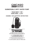
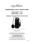
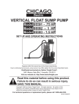
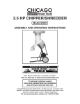
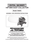
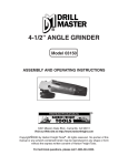
1/2 HP SUBMERSIBLE PUMP
(TRASH WATER TYPE)
Model 92481
ASSEMBLY AND OPERATING INSTRUCTIONS
®
3491 Mission Oaks Blvd., Camarillo, CA 93011
Visit our Web site at: http://www.harborfreight.com
TO PREVENT SERIOUS INJURY,
READ AND UNDERSTAND ALL WARNINGS
AND INSTRUCTIONS BEFORE USE.
Copyright© 2005 by Harbor Freight Tools®. All rights reserved. No portion of this
manual or any artwork contained herein may be reproduced in any shape or form
without the express written consent of Harbor Freight Tools.
For technical questions, please call 1-800-444-3353.
PRODUCT SPECIFICATIONS
Item
Electrical Requirements
Pump Type
Minimum Water Pick-up Height
Discharge Outlet Size
Maximum Discharge Capability
Maximum Size Particle Uptake
Pump Basin Required Size
Temperature Operating Range
Overall Dimensions
Weight
Description
120 Volt / 60 Hz / 1/2 HP / Single Phase
Continuous Run Thermal Overload Protection
3 Prong, Grounded Power Plug
Trash Water / Centrifugal / Pit Type / Self-Priming / Air Cooled
Maximum Lift: 36 Feet
4-3/4”
2” O.D.
71 Gallons Per Minute At Pump Outlet
1-3/8”
Minimum 18” Diameter
32° To 104° Fahrenheit
9-1/2” Diameter x 17” High
42.2 Pounds
SAVE THIS MANUAL
You will need this manual for the safety warnings and precautions, assembly, operating,
inspection, maintenance and cleaning procedures, parts list and assembly diagram.
Keep your invoice with this manual. Write the invoice number on the inside of the front
cover. Keep this manual and invoice in a safe and dry place for future reference.
UNPACKING
When unpacking, check to make sure all the parts shown on the Parts Lists on page 13
are included. If any parts are missing or broken, please call Harbor Freight Tools at the
number shown on the cover of this manual as soon as possible.
GENERAL SAFETY RULES
IMPORTANT SAFETY INSTRUCTIONS
WARNING!
READ AND UNDERSTAND ALL INSTRUCTIONS
Failure to follow all instructions listed below may result in
electric shock, fire, and/or serious injury.
SAVE THESE INSTRUCTIONS
REV 08/05
SKU 92481
For technical questions, please call 1-800-444-3353.
PAGE 2
WORK AREA
1.
Keep your work area clean and well lit. Cluttered and dark work areas
invite accidents.
2.
Do not operate the Sump Pump in explosive atmospheres, such as in the
presence of flammable liquids, gases, or dust. Electrical equipment creates
sparks which may ignite the dust or fumes.
3.
Keep bystanders, children, and visitors away while operating the Sump
Pump. Distractions can cause you to lose control.
ELECTRICAL SAFETY
1.
Grounded tools must be plugged into a GFCI (Ground Fault Circuit
Interrupter) outlet properly installed and grounded in accordance with all
codes and ordinances. Never remove the grounding prong or modify the plug in
any way. Do not use any adapter plugs. Check with a qualified electrician if you
are in doubt as to whether the outlet is properly grounded. If the tool should
electrically malfunction or break down, grounding provides a low resistance path
to carry electricity away from the user.
2.
Avoid body contact with grounded surfaces such as pipes, radiators,
ranges, and refrigerators. There is an increased risk of electric shock if your
body is grounded.
3.
Do not abuse the Power Cord. Never use the Power Cord to pull the Plug
from an outlet. Keep the Power Cord away from heat, oil, sharp edges, or
moving parts. Replace damaged Power Cords immediately. Damaged
Power Cords increase the risk of electric shock.
PERSONAL SAFETY
1.
Stay alert. Watch what you are doing, and use common sense when
operating a power tool. Do not use a power tool while tired or under the
influence of drugs, alcohol, or medication. A moment of inattention while
operating power tools may result in serious personal injury.
2.
Dress properly. Do not wear loose clothing or jewelry. Contain long hair.
Keep your hair, clothing, and gloves away from moving parts. Loose
clothes, jewelry, or long hair can be caught in moving parts.
SKU 92481
For technical questions, please call 1-800-444-3353.
PAGE 3
3.
Avoid accidental starting. Be sure the circuit supplying electrical power is
off before plugging in. Plugging in a Sump Pump with the electrical circuit on
invites accidents.
4.
Do not overreach. Keep proper footing and balance at all times. Proper
footing and balance enables better control of the Sump Pump in unexpected
situations.
5.
Always wear eye protection. Wear ANSI approved safety impact
goggles and nonskid rubber boots. A hard hat must be used for
appropriate conditions.
TOOL USE AND CARE
1.
Do not force the Sump Pump. Use the correct Pump for your application.
The correct Pump will do the job better and safer at the rate for which it is
designed.
2.
Do not use the Sump Pump if the electrical circuit system does not turn it
on or off. Any electrical circuit system that cannot be controlled is dangerous
and must be repaired or replaced.
3.
Turn off the electric power to the outlet supplying power to the Sump Pump
and disconnect the Pump’s Power Plug from the outlet before making any
adjustments, changing accessories, or storing the Sump Pump. Such
preventive safety measures reduce the risk of starting the tool accidentally.
4.
Store idle tools and equipment out of reach of children and other untrained
persons. Tools and equipment are dangerous in the hands of untrained users.
5.
Maintain the Sump Pump with care. Keep the Pump clean. Properly
maintained Sump Pump equipment is easier to control. Do not use damaged
equipment. Tag damaged equipment “Do not use” until repaired.
6.
Check for misalignment or binding of moving parts, broken parts, and any
other condition that may affect the Sump Pump’s operation. If damaged,
have the Pump serviced before using. Many accidents are caused by poorly
maintained tools and equipment.
7.
Use only accessories that are recommended by the manufacturer for your
model. Accessories that may be suitable for one tool may become hazardous
when used on another Sump Pump.
SKU 92481
For technical questions, please call 1-800-444-3353.
PAGE 4
SERVICE
1.
Sump Pump service must be performed only by qualified repair personnel.
Service or maintenance performed by unqualified personnel could result in a risk
of injury.
2.
When servicing the Sump Pump, use only identical replacement parts.
Follow instructions in the “Inspection, Maintenance, And Cleaning”
section of this manual. Use of unauthorized parts or failure to follow
maintenance instructions may create a risk of electric shock or injury.
GROUNDING
WARNING!
Improperly connecting the grounding wire can result in the risk of electric
shock. Check with a qualified electrician if you are in doubt as to whether the
outlet is properly grounded. Do not modify the power cord plug provided with
the tool. Never remove the grounding prong from the plug. Do not use the
tool if the power cord or plug is damaged. If damaged, have it repaired by
a service facility before use. If the plug will not fit the outlet, have a proper
outlet installed by a qualified electrician.
GROUNDED TOOLS: TOOLS WITH THREE PRONG PLUGS
1.
Tools marked with “Grounding Required” have a three wire cord and three prong
grounding plug. The plug must be connected to a properly grounded outlet. If
the tool should electrically malfunction or break down, grounding provides a low
resistance path to carry electricity away from the user, reducing the risk of
electric shock. (See Figure A, next page.)
2.
The grounding prong in the plug is connected through the green wire inside the
cord to the grounding system in the tool. The green wire in the cord must be the
only wire connected to the tool’s grounding system and must never be attached
to an electrically “live” terminal. (See Figure A.)
3.
Your tool must be plugged into an appropriate outlet, properly installed and
grounded in accordance with all codes and ordinances. The plug and outlet
should resemble those in Figure A.
SKU 92481
For technical questions, please call 1-800-444-3353
PAGE 5
3-PRONG PLUG
120 VOLT,
GROUNDED,
ELECTRICAL OUTLET
FIGURE A
SYMBOLOGY
Double Insulated
Canadian Standards
Association
Underwriters
Laboratories, Inc.
V~
A
FIGURE B
no
xxxx/min.
Volts Alternating Current
Amperes
No Load Revolutions
per Minute (RPM)
SPECIFIC SAFETY RULES
1.
Maintain labels and nameplates on the Sump Pump. These carry important
information. If unreadable or missing, contact Harbor Freight Tools for a
replacement.
2.
Use the right product for the right job. There are certain applications for
which this product was designed. Do not use small equipment, tools, or
attachments to do the work of larger industrial equipment, tools, or attachments.
Do not use this product for a purpose for which it was not intended.
3.
WARNING! Risk of electrical shock. Always disconnect the Sump
Pump from its power source before handling or making any adjustments. Always
SKU 92481
For technical questions, please call 1-800-444-3353.
PAGE 6
wear nonskid rubber boots when water is on the floor and you must unplug the
Sump Pump. Never allow the Motor to get wet. Make sure the electrical power
source is a separately fused, grounded, 3-wire type GFCI outlet of 15 AMP
capacity. DO NOT REMOVE THE GROUND PRONG OR PLUG. DO NOT USE
AN EXTENSION CORD.
4.
WARNING! Always arrange a “drip loop” in the Power Cord (1)
connecting the Sump Pump to a 120 volt, GFCI electrical outlet. A drip loop is
that part of the Power Cord below the level of the outlet to prevent water from
traveling along the Power Cord and coming in contact with the outlet. If the Power
Plug or electrical outlet does get wet, do not unplug the Power Cord. Disconnect
the fuse or circuit breaker that supplies power to the Sump Pump. Then, unplug
the Power Cord and examine for presence of water in the outlet. (See Figure C.)
WATER DRIPS OFF CORD,
AWAY FROM OUTLET.
FIGURE C
5.
Do not pump hazardous materials. Do not pump explosive or flammable
materials such as fuel oil, kerosene, gasoline, etc. Do not pump in close proximity
to flammable or explosive materials. Do not pump fats, oils, salt or waste water.
The Sump Pump is designed to move clean or dirty water only. Do not pump
water over 104 degrees Fahrenheit.
6.
Make sure the discharge hose (not included) is secured to a solid surface to
ensure the stability of the Sump Pump.
7.
Make sure to position the Base of the Sump Pump on a flat, level surface.
8.
If necessary, have a certified electrician install a 120 volt, grounded, GFCI
electrical outlet that is dedicated only to the Pump. Any outlet should be
above the water line.
9.
NEVER raise or lower the Sump Pump by its electrical Power Cord. Firmly
attach the accessory polypropylene Rope to the Handle of the Sump Pump. Use
the Rope only to raise or lower the Sump Pump.
SKU 92481
For technical questions, please call 1-800-444-3353.
PAGE 7
10.
In cold weather, when the Sump Pump is not in use, protect the interior of
the Pump from freezing by draining the liquid and pumping a permanent
type automobile antifreeze containing a rust inhibitor through the system.
A 50% mixture with water is recommended. Be sure to flush the system with a
neutralizing liquid prior to reuse of the unit.
11.
Prior to use, and periodically thereafter, check to make sure all connections
are tight and secure.
12.
Industrial applications must follow OSHA requirements.
13.
Performance of this machine (if powered by line voltage) may vary
depending on variations in local line voltage.
14.
WARNING! People with pacemakers should consult their physician(s)
before using this product. Operation of electrical equipment in close proximity to
a heart pacemaker could cause interference or failure of the pacemaker.
15.
WARNING! The warnings and cautions discussed in this manual cannot
cover all possible conditions and situations that may occur. It must be understood
by the operator that common sense and caution are factors which cannot be built
into this product, but must be supplied the operator.
SAVE THESE INSTRUCTIONS
ASSEMBLY AND OPERATING INSTRUCTIONS
NOTE: For additional information regarding the parts listed in the following pages, refer
to the Assembly Diagram on page 14.
1.
If necessary, have a certified electrician install (within 14 feet of where the Sump
Pump will be located) a 120 volt, GFCI electrical outlet that is dedicated only
to the Pump. Any outlet should be above the water line.
2.
WARNING! Always make sure to turn off the electricity powering the Sump
Pump’s electrical outlet and that the Sump Pump is unplugged from its outlet
prior to assembling the unit, unclogging the unit, or making any adjustments to
the unit.
3.
NOTE: The size of the discharge outlet on the Connector Plug (39) is 2”
diameter. Only use a hose (not included) that will fit the Connector Plug. Note:
Using a hose that is too small will affect Pump flow and performance.
(See Figure D, next page.)
SKU 92481
For technical questions, please call 1-800-444-3353.
PAGE 8
4.
Connect the Discharge Hose to the Connector Plug (39) of the
Sump Pump, using the Discharge Hose Clamp (40) to secure the Discharge
Hose in place. (See Figure D.)
5.
Install a Union (not included) or other means of separating the Discharge Hose
just above the floor to facilitate removal of the Sump Pump if necessary.
(See Figure D.)
6.
Set the Sump Pump in place, using the accessory Rope (41). Do not raise or
lower the Sump Pump by its Power Cord or by its Discharge Hose.
(See Figure D.)
7.
Connect additional Discharge Pipe as needed to direct the discharge to the
desired location. The discharge should be kept as short as possible with
a minimum number of turns. NOTE: The maximum lift of the Pump is 36 feet.
See the Flow Chart (Figure E, next page), indicating gallons pumped per
minute at various lift heights.
8.
Plug the Power Cord into its 120 volt, GFCI electrical outlet while making sure to
form a “drip loop” in the Power Cord. Then, turn on the electrical power to the
GFCI electrical outlet. (See Figure B.)
POWER CORD/PLUG (1)
UNION
(NOT INCLUDED)
DISCHARGE HOSE
(NOT INCLUDED)
DISCHARGE HOSE CLAMP
(40)
CONNECTOR PLUG
(39)
FIGURE D
SKU 92481
For technical questions, please call 1-800-444-3353.
PAGE 9
9.
The Sump Pump will now start and run continuously until electrical power to the
Pump is shut off.
10.
When shutting off power to the Sump Pump, always shut off the electrical
power to the GFCI outlet first. Then, disconnect the Sump Pump’s Power
Plug from the GFCI outlet.
Flow Chart
FT
35
30
25
20
15
0
FIGURE E
10
20
30
40
50
60
70
GPM
TROUBLESHOOTING
1.
WARNING! Always make sure the electrical power to the Sump Pump’s
GFCI electrical outlet is shut off first and then the Pump is unplugged from its
outlet prior to performing any maintenance to the unit. This Section is designed
to help identify reasons for operating problems. It is not a service guide.
Dismantling the Sump Pump voids warranty. Servicing of the Sump Pump (other
than simple cleaning or unplugging) should be done only by a qualified service
technician.
2.
Pump Motor does not run.
A. Line circuit breaker may be off. Have a certified electrician check the fuse or
breaker.
B. Water level in pit may be too low. Add more water to pit.
C. Power Cord may not be making contact in electrical outlet. Check connection.
3.
Pump Motor Runs, but does not discharge water.
A. Discharge Hose may be frozen or blocked. Check to see if Discharge Hose
passes through cold areas or is blocked.
B. Vertical lift is beyond Sump Pump’s capability. Maximum lift capability is 36
feet.
SKU 92481
For technical questions, please call 1-800-444-3353.
PAGE 10
C. Inlet screen of Sump Pump is blocked, or Impeller is jammed. Remove Pump
and clean the Impeller.
4.
Pump Motor runs, but delivers small amount of water.
A. Vertical lift is approaching Sump Pump’s maximum lift capability. Maximum
lift capability is 36 feet. Reduce height of vertical lift.
B. Inlet is partially blocked. Check to make sure inlet is clear of debris.
C. Discharge Hose is partially blocked. Check Hose for blockage.
5.
Circuit breaker trips or fuse blows when Sump Pump starts.
A. Breaker or fuse size is too small. A minimum 15 AMP breaker or fuse should
be used.
B. Other major appliances are on the same circuit. Sump Pump should be on its
own separate circuit.
C. Sump Pump is connected to an extension cord, or wiring is inadequate. DO
NOT USE EXTENSION CORDS. Have a qualified service technician check
for proper wiring.
D. Defective Switch or Motor. Have a qualified service technician check Switch
and Motor for proper operation.
INSPECTION, MAINTENANCE, AND CLEANING
1.
WARNING! Always make sure the electrical power to the Sump Pump’s
GFCI electrical outlet is shut off first and then the Pump is unplugged from its
outlet prior to performing any inspection, maintenance, or cleaning to the unit.
2.
Before each use, inspect the general condition of the Sump Pump. Check for
clogs throughout the system, misalignment or binding of moving parts, damaged
electrical wiring, damaged or loose discharge hoses, and any other condition that
may affect its safe operation. If abnormal noise or vibration occurs, have the
problem corrected before further use. Do not use damaged equipment.
3.
If the Sump Pump is not in use due to dry conditions, etc., pour enough
water into the pit to activate the Pump once every 3 months.
4.
Periodically, check to make sure the pit is free from accumulated debris, rocks,
and other objects that may damage the Sump Pump.
5.
When cleaning, spray the exterior and Impeller of the Sump Pump with a garden
hose. Do not introduce water or any other liquid into the Motor Housing.
6.
In cold weather, when the Sump Pump is not in use, protect the interior of the
Pump from freezing by draining the liquid and pumping a permanent type
automobile antifreeze containing a rust inhibitor through the system. A 50% mixture
SKU 92481
For technical questions, please call 1-800-444-3353.
PAGE 11
with water is recommended. Be sure to flush the system with a neutralizing liquid
prior to reuse of the unit.
7.
Every two years: Change the oil in the Sump Pump. The Pump holds
approximately 4-3/4 ounces of oil. Always use a quality grade pump oil (i.e.,
Castrol ® Magna GC32). To change the oil, unscrew and remove the Screw (18)
located on the side of the Sump Pump. Turn the Pump on its side to drain the old
oil into an oil waste can. Fill the Pump with the new oil. Replace the Screw.
Then, lift the Pump to its upright position. NOTE: Always dispose of old oil
properly, according to federal, state, and local guidelines. (See Figure F.)
8.
CAUTION! All maintenance, service, or repairs not listed in this
manual are only to be attempted by a qualified service technician.
SCREW (18)
FIGURE F
PLEASE READ THE FOLLOWING CAREFULLY
THE MANUFACTURER AND/OR DISTRIBUTOR HAS PROVIDED THE PARTS LIST AND
ASSEMBLY DIAGRAM IN THIS MANUAL AS A REFERENCE TOOL ONLY. NEITHER THE
MANUFACTURER OR DISTRIBUTOR MAKES ANY REPRESENTATION OR WARRANTY OF
ANY KIND TO THE BUYER THAT HE OR SHE IS QUALIFIED TO MAKE ANY REPAIRS TO THE
PRODUCT, OR THAT HE OR SHE IS QUALIFIED TO REPLACE ANY PARTS OF THE
PRODUCT. IN FACT, THE MANUFACTURER AND/OR DISTRIBUTOR EXPRESSLY STATES
THAT ALL REPAIRS AND PARTS REPLACEMENTS SHOULD BE UNDERTAKEN BY
CERTIFIED AND LICENSED TECHNICIANS, AND NOT BY THE BUYER. THE BUYER
ASSUMES ALL RISK AND LIABILITY ARISING OUT OF HIS OR HER REPAIRS TO THE
ORIGINAL PRODUCT OR REPLACEMENT PARTS THERETO, OR ARISING OUT OF HIS OR
HER INSTALLATION OF REPLACEMENT PARTS THERETO.
SKU 92481
For technical questions, please call 1-800-444-3353.
PAGE 12
PARTS LIST
Part #
1
2
3
4
5
6
7
8
9
10
11
12
13
14
15
16
17
18
19
20
21
Description
Power Cord/Plug
Screw
Screw
Spring Washer
Pump Handle
Name Plate
Upper Pump Case
Screw
Spring Washer
Rubber Seal
Capacitor
Middle Cover
Wave Washer
Terminal Housing
Motor (Stator & Rotor)
Key
Middle Pump Case
Screw
O-Ring
Mechanical Seal
Qty.
1
2
2
2
1
1
1
4
4
1
1
1
1
1
1
1
1
1
1
1
1
Part #
22
23
24
25
26
27
28
29
30
31
32
33
34
35
36
37
38
39
40
41
Description
Flange
Screw
Oil Seal
Impeller
Lock Washer
Nut
Rubber Seal
Lower Pump Case
Plain Washer
Spring Washer
Screw
Nut
Spring Washer
Plain Washer
Rubber Seal
Discharge Flange
Screw
Connector Plug
Discharge Hose Clamp
Rope
Qty.
1
3
1
1
1
1
1
1
4
4
4
2
2
2
1
1
2
1
1
1
NOTE:
Some parts are listed and shown for illustration purposes only,
and are not available individually as replacement parts.
SKU 92481
For technical questions, please call 1-800-444-3353.
PAGE 13
ASSEMBLY DIAGRAM
41: ROPE NOT SHOWN.
NOTE:
Some parts are listed and shown for illustration purposes only,
and are not available individually as replacement parts.
SKU 92481
For technical questions, please call 1-800-444-3353.
PAGE 14