1
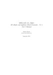
10
Channel Vision Technology will repair or replace any defect in material or
workmanship which occurs during normal use of this product with new or rebuilt
parts, free of charge in the USA, for ten years from the date of original purchase.
This is a no hassle warranty with no mail in warranty card needed. This warranty
does not cover damages in shipment, failures caused by other products not
supplied by Channel Vision Technology, or failures due to accident, misuse, abuse,
or alteration of the equipment. This warranty is extended only to the original
purchaser, and a purchase receipt, invoice, or other proof of original purchase date
will be required before warranty repairs are provided.
Mail in service can be obtained during the warranty period by calling (800) 8400288 toll free. A Return Authorization number must be obtained in advance and
can be marked on the outside of the shipping carton.
This warranty gives you specific legal rights and you may have other rights (which
vary from state to state). If a problem with this product develops during or after the
warranty period, please contact Channel Vision Technology, your dealer or any
factory-authorized service center.
Channel Vision products are not intended for use in medical, lifesaving, life
sustaining or critical environment applications. Channel Vision customers using or
selling Channel Vision products for use in such applications do so at their own risk
and agree to fully indemnify Channel Vision for any damages resulting from such
improper use or sale.
Specifications:
Video In/Out:
Video format:
Surge Suppression:
Transmission distance:
Operation freq. range:
Twisted pair connector:
Common mode rejection:
Wire type:
Dimensions:
CH
BNC male connector
RS170, NTSC, CCIR or SECAM
6,000V
Max. 1000 ft.
0 to 6MHz
Two screw terminals
60dB
1-pair, UTP Category 5, 5e or 6
1.26” x 0.83” x 0.59”
32mm x 21mm x 15mm
Specifications subject to change without notice.
AN
N
EL
B-
20
1
B-201
1-Camera Passive Video Balun
www.channelvision.com
234 Fischer Avenue, Costa Mesa, California 92626 USA
(714)424-6500 (800)840-0288 (714)424-6510 fax
email: [email protected]
500-272 rev A
10
VI
SI
O
N
TM
Installation Diagram
Model B-201
The B-201 video balun provides the necessary impedance
transformation to transition from 75 ohm coax to twisted pair
cabling. It is a great way to deliver video from a security
camera when you only have a twisted pair ran to the camera
location and no coax. The low cost, simplicity, and availability
of twisted pair cable, makes the B-201 a convenient choice
for both new construction and retro-fit applications.
Model B-201
Any standard camera
or composite video signal
CH
AN
N
EL
B-
20
1
VI
SI
O
N
TM
Video
Features:
CH
AN
N
EL
B-2
01
VIS
IO
N
TM
hEasy installation
hSends video over 1,000 ft. of twisted pair
Power
hCompatible with Category 5, 5e, and 6 wiring
Up to 1,000 ft.
of
CAT5 cable
To Monitor
or
Video distribution
hSmall size allows installation in crowded spaces
B-2
AN
NEL
01
VIS
N
IO
TM
BNC connector
for standard
75-ohm video cable
CH
If necessary, use another
pair in the twisted pair
cable to make a power
supply extension.
Camera
power supply
Installation:
h Connect video signal to the BNC connector of the B-201.
CH
AN
h Attach a matched pair from your twisted pair cable to the
screw terminals on the B-201.
N
EL
B20
1
2
Screw terminal
connections for
twisted pair
VI
SI
O
N
TM
h If there is no power available for the camera, cut the
connector off of the end of the power supply and use
another pair from your twisted pair cable to splice in an
extension.
3