1
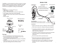
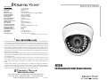
*Specifications:
Image Sensor:
Picture Elements:
Resolution:
S/N Ratio:
Min Illumination:
Electronic Shutter:
Flickerless Mode:
Gain Control:
Auto White Balance:
Back Light Comp.:
Gamma Characteristic:
Camera Lens:
Sync. System:
Power Requirements:
Power Consumption:
Infrared Illumination:
LED Wavelength:
Illumination Distance:
Video Output:
Dimensions:
Operating Temp:
1/3” Hi-Res CCD
NTSC: 768x494
540 lines
More than 48 dB
0.03 LUX @ F2.0(Day), 0 LUX @ F2.0(Night)
1/60s - 1/100,000s
ON/OFF switchable
High/Low switchable
Automatic
ON/OFF switchable
0.45
3.6mm Fixed Lens
Internal, Negative sync.
12VDC
80mA (IR off), 360mA (IR on - max)
24 IR LEDs
850nm
60 feet
1 Vp-p @ 75 ohms
Dia. 4.39”, Height 3.27”
-10°C to 50°C (14°F to 122°F)
*Specifications subject to change without notice.
1
Channel Vision Technology will repair or replace any defect in material or workmanship which
occurs during normal use of this product with new or rebuilt parts, free of charge in the USA, for
one year from the date of original purchase. This is a no hassle warranty with no mail in
warranty card needed. This warranty does not cover damages in shipment, failures caused by
other products not supplied by Channel Vision Technology, or failures due to accident, misuse,
abuse, or alteration of the equipment. This warranty is extended only to the original purchaser,
and a purchase receipt, invoice, or other proof of original purchase date will be required before
warranty repairs are provided.
Mail in service can be obtained during the warranty period by calling (800) 840-0288 toll free.
A Return Authorization number must be obtained in advance and can be marked on the outside
of the shipping carton.
This warranty gives you specific legal rights and you may have other rights (which vary from
state to state). If a problem with this product develops during or after the warranty period,
please contact Channel Vision Technology, your dealer or any factory-authorized service
center.
Channel Vision products are not intended for use in medical, lifesaving, life sustaining or
critical environment applications. Channel Vision customers using or selling Channel Vision
products for use in such applications do so at their own risk and agree to fully indemnify
Channel Vision for any damages resulting from such improper use or sale.
www.channelvision.com
234 Fischer Avenue, Costa Mesa, California 92626 USA
(714)424-6500 (800)840-0288 (714)424-6510 fax
email: [email protected]
500-267 Rev C
6126
IR Illuminated Color Dome Camera
10
Model 6126
The 6126 is an IR Illuminated Color Dome Camera. Its stylish
design and small size make it ideal for residential and small
business CCTV installations where the camera must be
unobtrusive and capable of viewing in total darkness.
VR Adjustment level for DC Drive Lens
(Switch AES OFF before adjusting)
2-Conductor power
supply extension
(not included)
Crimp-on splice
connectors
(not included)
BNC connector
Coax extension
(not included)
Mounting Screws
Important Note:
No more than one 6126 should be used with
Channel Vision’s P-6014 camera sequencer.
To Monitor
or
Video distribution
Installation:
Set Screw
Dome Cover
120º Pan
120º Tilt
360º
Horizontal
Rotation
Power supply
(included)
h Remove the dome cover by rotating it counter clockwise.
h Drill a hole in the wall or ceiling for wiring (see diagram).
Power Supply
Base
2
Camera Adjustments
FL: Flicker Lens ON/OFF
AGC: Auto Gain Control High/Low
AES: Auto Electronic Shutter ON/OFF
BLC: Back Light Compensation ON/OFF
Features:
h High quality 1/3” Hi-Res CCD sensor
h 540 TV lines of resolution
h 24 piece LED IR illuminator with built-in light sensor
h View images 60 feet away in total darkness
h Automatic Gain Control (AGC) and Auto White Balance
(AWB)
h Easy to install
Dome Camera
3. Adjust camera settings
4. Attach dome
1. Connect wiring
2. Mount base
Warnings:
h Do not look directly into the illuminator when in use.
h Do not touch the body of the unit when in use. It can
reach temperatures as high as 150ºF.
h Do not point the illuminator directly at paper or flammable
materials.
h Avoid touching the lens with fingers. Clean off any finger
prints with cleaning alcohol and cotton swabs.
h If necessary, attach the camera’s video output to a coax
extension that is long enough to reach your monitor or
video distribution equipment.
h If necessary, cut the connector off of the end of the power
supply and splice in an extension using crimp-on
connectors.
h Mount the base with the provided screws.
h Move the camera body to adjust the view and make
electronic adjustments using the dip switches.
h Re-attach the dome cover by rotating it in a clockwise
direction. Secure it in place with the small set screw
provided.
3