1
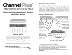
Set-up Diagram
R
Outputs to 12 TVs
PERFORMANCE MULTI-ROOM VIDEO
Model 2602A
In-wall Cabinet
Media Center
Model 2203
DIN rail
Model 2614A
Panel
Model 5314
Modulators
Model 2214
4-way DIN Combiner
Model 5314
Modulators
ChannelPlus
Model 5314
DIN-mount Camera Modulator
Owner's Manual
Modulator
INPUT
OUT
OUT
IN
OUT
IN
OUT
Model 2514A 5MHz to 1000MHz
SPLITTER
IN
IN
IN
OUT
SPLITTER
OUT
IN
OUT
IN
IN
OUT
IN
IN
OUT
IN
OUT
SPLITTER
OUT
IN
IN
COMBINER
OUT
IN
OUT
IN
Model 3212A
Coaxial Cable Panel
IN
Model 2514A 5MHz to 1000MHz
SPLITTER
COMBINER
OUT
Model 2514A 5MHz to 1000MHz
Long coax 130-200 ft
Model 2514A 5MHz to 1000MHz
COMBINER
OUT
Outputs
ChannelPlus
Medium coax 70-130 ft
Short coax 0-70 ft
OUT
Outputs
ChannelPlus
Outputs
ChannelPlus
OUT
IN
ChannelPlus
OUT
IN
COMBINER
OUT
IN
OUT
IN
IRR
ChannelPlus
®
Input
Cable/Antennae
Warranty
VIDEO
Multiplex Technology, Inc., warrants this product to be free from defects in
materials and workmanship for a period of one year from the date of
purchase or MTI will repair or, at its option, replace the defective product.
To obtain warranty service, call MTI for a Return Material Authorization
(RMA) number and return the product pre-paid accompanied by a copy of
the purchase receipt, to Multiplex Technology, Inc., 3001 Enterprise St.,
Brea, CA 92821, Attn: Customer Service. Please put the RMA number on
the outside of the carton.
NORM
POWER
Any implied warranty arising from the sale of the product including implied
warranties of merchantability and fitness for purpose are limited to the
warranty stated above. MTI shall not be responsible for any loss, damages
or expenses, whether direct, consequential, or incidental arising from the
use or inability to use this product. Some states do not allow limitations on
how long an implied warranty lasts or the exclusion or limitation or
incidental or consequential damages, so the above limitations may not
apply to you. This warranty gives you specific legal rights, and you may
have other rights which vary from state to state.
multiplex
600-048A
2/9/96
®
multiplex
technology, inc.
HI Z
3001 Enterprise Street, Brea, CA 92821-6213, U.S.A.
714-996-4100 * 800-999-5225 * FAX 714-996-4900
®
technology, inc.
3001 Enterprise St., Brea, CA 92821-6213. U.S.A.
714-996-4100 * 800-999-5225 * Fax 714-996-4900
Mounting Options
Model 5314
Model 2203
DIN rail
Up to four
Model 5314
Modulators
R
Up to 4 Model 5314
Modulators
Model 2214
Combiner
Video input
(BNC)
Selectable termination
Power LED
Power input
or
Apply channel
reminder here
RF output
DIP switch programs
channel choice
Channel Selection
Guide
CABLE CHANNELS
IRC
HRC
Model 2614A
Panel
Specifications
O
N
O
N
Output
Input
54
O
N
63
O
N
72
O
N
81
O
N
55
O
N
64
O
N
73
O
N
82
O
N
56
O
N
65
O
N
74
O
N
83
O
N
57
O
N
66
O
N
75
O
N
84
O
N
58
O
N
67
O
N
76
O
N
85
O
N
59
O
N
68
O
N
77
O
N
86
O
N
60
O
N
69
O
N
78
O
N
61
O
N
70
O
N
79
O
N
62
O
N
71
O
N
80
O
N
UHF CHANNELS
14
O
N
22
O
N
30
O
N
15
O
N
23
O
N
31
O
N
16
O
N
24
O
N
32
O
N
17
O
N
25
O
N
33
O
N
18
O
N
26
O
N
34
O
N
19
O
N
27
O
N
35
O
N
20
O
N
28
O
N
21
O
N
29
O
N
Input
connector
Video
Termination
Frequency
Range
UHF
CATV
25 dBmV
Video: 1Vp-p @ 75W
Format: NTSC
1 BNC
75 W or > 1 M
in "Loop" position
W
(switch selectable)
Channel 14 to 35
Channel 54 to 86
Frequency
Stability
± 5 kHz
Temperature
Operating
Storage
32 F (0 C) to 122 F (50 C)
O
O
O
O
-22 F (-30 C) to 122 F (50 C)
O
O
O
O
Power Supply
Model 350-067 (included)
Input: 120 VAC, 60 Hz
Output: 12 VAC, 400 mA
Dimensions
4.2"(H) x 1.5"(W) x 3.1"(D)
Weight
1 lb
Shipping
Weight
2 lbs