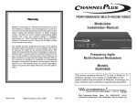
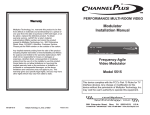
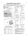
1
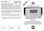
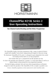
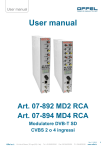
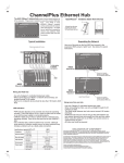
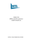
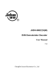
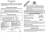
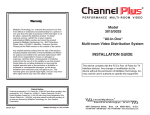
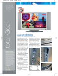
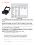
Channel ® Controls and Connections This ChannelPlus model 3515 video distribution system contains a digitally-tuned video modulator that converts any baseband video and audio signal to a userselected UHF, or Ultraband CATV channel. An internal quartz crystal reference PERFORMANCE MULTI-ROOM VIDEO oscillator and PLL circuitry ensure drift-free performance. The user selects the output frequency (channel) using the "program" button to enter the number of the desired channel. Optionally, the model 3515 may be programmed by a computer running Windows 95. Multi-room Video Distribution System Installation Manual Any TV connected to the output via coax can receive the signals, when the TV is tuned to the proper channel. Model 3515 - Modulator section POWER 15VDC 300mA OUTPUT model 3515 integrated modulator & distribution system IN OUT AUDIO VIDEO pwr IR IR pll frequency control model 3515 integrated modulator & distribution system RF output Program switch to enter the channel number Power supply (Use a paper clip) when IR data is Audio input: Ant / CATV INPUT To TVs IR LED shows Audio loop-thru For use with model 2133 IR targets OUTPUTS MODULATORS INPUTS 15VDC 300mA being transmitted Right and left are Power LED also combined for monaural aids in programming Video input To TVs MODULATORS For use with model 2133 IR targets OUTPUTS Connection for Model 3515 - RF section INPUTS Outputs for IR emitter Ant / CATV pll frequency control INPUT pwr IR Modulator Section Model 3515 (Requires coax cable, RG-6 recommended) Expansion input for other modulators (25dBmV max) } This device complies with the FCC's Part 15 Rules for TV interface devices. Any change or modification to this device without the permission of Multiplex Technology, Inc. may void the user's authority to operate this equipment. Outputs for TVs (8) Input for cable or antenna Programming the model 3515 by computer: You may program the channel assignment from a front panel switch or by a computer multiplex running Windows 95. You will need to download the instructions from our web site, ® http://www.channelplus.com. The files are located in the Integrated Modulator section. Run the program to extract the files and follow the instructions in the readme.txt file. technology, inc. You must have a sound card capable of generating wav files. 3001 Enterprise Street, Brea, CA 92821-6213, U.S.A. 714-996-4100 * 800-999-5225 * FAX 714-996-4900 * www.channelplus.com An audio loop thru is provided so that the 3515 may be placed between the computer and speaker system. 2 Sample System Diagram Manual Programming Examples: In this system, CATV or antenna channels are available on all TVs. In addition, the DVD player inside the computer will play DVD movies on channel 70 on all TVs. To powered speakers To program modulator to channel 67 (2 digit channel #) model 3515 integrated modulator & distribution system Press program switch 6 times pwr IR pll frequency control Cables supplied IR pwr Wait for pwr LED to light (ready for next number.) To video/audio Model 3515 outputs of computer POWER 15VDC 300mA IN OUT OUTPUT AUDIO VIDEO IR pwr Press program switch 7 more times IR IR pwr Attach the model 2173 IR emitter directly over the target for IR mouse or IR trackball. Cable supplied for connection to RCA type audio jacks.. To program modulator to channel 120 (3 digit channel #) RG6 coax preferred model 3515 integrated modulator & distribution system Press program switch 1 time To more TVs pwr pwr IR pll frequency control IR Wait for pwr LED to light (ready for next number.) Any or all TVs may have a model 2133 IR Target pwr Press program switch 2 more times RF section IR (Distributes to as many as 8 TVs) Control the DVD pwr IR Wait for pwr LED to light (ready for next number.) from any room using IR mouse CATV/Antenna or trackball. pwr Press program switch 10 more times (press 10 to enter a ‘zero’) Expansion port The 3515 RF section has an expansion port to allow for additional video modulators. pwr IR E.g. you may add a front door camera that would be viewed on channel 73 and an LV player viewed on channel 75. The expansion port has > 85dB of antenna isolation required by FCC part 15 when using video modulators with an antenna. 3 4 IR Valid Channels: Things to watch for: 14-64: UHF channels 65-125: CATV channels 95-99: not valid No picture Verify that the video source is on and is producing a video signal. Check that the TV and the modulator are tuned to the same channel. For example, if the modulator is broadcasting on UHF channel 16, make sure the TV is on UHF 16 rather than CATV 16. UHF 16 Channel Spacing: Skip at least one number between the modulator channel and broadcast channels. Channels 14 and 16: OK. Channels 14 and 15: Illegal. and CATV 16 are at different frequencies. Weak ChannelPlus UHF channel If the TV has a separate UHF input, be sure that it is connected. LEDs blink ... The display will blink if you have made an illegal choice. See the section on programming. Error indication: If an error has occurred or an incorrect channel is entered, the LED will flash quickly for a second and return to the previous settings. Herringbone interference on ChannelPlus channel (diagonal lines) ... You may have chosen a channel number that is not completely vacant. Distant UHF stations may be un-watchable, but will cause interference if you try to create a new channel at the same frequency. Also, cable companies often have extra signals where there should be none. Try moving the ChannelPlus channel to another number. You may have to add a low pass filter to Channel number readback: A readback mode will display the current channel assignments. remove cable company noise. If a filter does not work, try adding a DC-block to remove common mode interference. Herringbone interference on many channels, including ChannelPlus channels (disappears when you remove the CATV/Ant feed) The RF amplifier can be overloaded by abnormally strong signals. Often, you can cure the problem with a simple attenuator. Use a variable attenuator and try to find a signal level where the interference just disappears. Sometimes, the problem is one station that is far stronger than the rest. In this case, attenuating all of the signals with a simple attenuator will cause the desired stations to be weak (snowy). In this case you must reduce the strength of only the offending station. A common FM trap will help if the problem is a nearby FM tower. If the problem is a nearby TV station, often the To read-back modulator channel assignment station management can provide suitable filters. (example: 3515 has been programmed to channel 108) Audio volume is low The left and right audio inputs are combined for monaural. For proper audio level, both right and left inputs must be used. If you have a mono source, connect it to both model 3515 integrated modulator & distribution system Hold program button down while applying power pwr right and left inputs using an RCA Y connector. IR pll frequency control No color on ChannelPlus channels You may have chosen the incorrect cable standard. Not all televisions can accommodate the 1.25MHz frequency difference between the H and I cable pwr standards. See the section on programming. IR Infrared Remote Control Problems Use the red Led blinks 1 time & pauses pwr IR Led blinks 10 times & pauses (“10” is read back as 0) If the light is on constantly, one or more IR targets is receiving electrical or optical noise. At the modulator section unit, begin to disconnect the outputs to the TVs until the IR DATA light goes off. This will tell you which IR target is the source of the noise. Next cover the front of the offending IR target. If the pwr IR DATA light on the side of the modulator section as a trouble shooting aid. This light will blink as remote control signals are relayed. IR IR DATA light turn off, the IR target is seeing a source of IR noise, such as a solid state flourescent lamp. Led blinks 8 times If the light does not go out, the problem may be radiated electrical noise from the TV. Reposition this IR target. If repositioning the IR target does not help, the TV may be conducting noise from its input. pwr IR Place a DC block between the IR target and the TV. If the IR DATA light seems to indicate proper operation, but the component is not being controlled, the IR emitter may be mis-located. Be sure the emitters are in front of the IR sensor. Simple DC-block for RF 5 Inexpensive 0-20dB attenuator 6 Changing modulation standards Cable HRC and IRC considerations Most cable services use IRC frequency assignments. This is the default for the ChannelPlus 3515 modulator. However, if the cable service uses HRC or the TV appears to search for the "house channels," the modulator can be reprogrammed to use HRC assignments by entering the number 98. Set to IRC by entering a 99. Both of these settings are only used for setting HRC/IRC. Warranty Common questions Can an amplifier be used on an output to drive signals over longer cable paths? No. The IR remote control feature will be defeated if an external amplifier is used. Multiplex Technology, Inc. warrants this product to be free from defects in materials and workmanship for a period of one year from the date of purchase or MTI will repair, or at its option, replace the defective product. To obtain warranty service, call MTI for a return material authorization (RMA) number and return the product prepaid to Multiplex Technology, Inc., 3001 Enterprise Street, Brea, CA 92821, Attention: Customer Service. Please put the RMA number on the outside of the carton. Can a splitter be used on one or more outputs in order to add more TVs? No. The model 3515 Multi-room Video Distribution System is a pre-engineered system providing optimum signal levels to each TV for clear, crisp picture quality. Each time a splitter is added, there is lowering of signal level called insertion loss. Insertion losses upset system performance. Additionally, the IR remote control feature will be defeated. To hang with connectors on the side To hang with connectors on the bottom or top Mounting hole template O Any implied warranty arising from the sale of the product including implied warranties of merchantability and fitness for purpose are limited to the warranty stated above. MTI shall not be responsible for losses or damages or expenses, whether direct, consequential or incidental arising from the use of or the inability to use this product. Some states do not allow limitations on how long the implied warranty lasts or the exclusion or limitation or incidental or consequential damages, so the above limitations and exclusions may not apply to you. This warranty gives you specific legal rights, and you may have other rights which may vary from state to state. O Specifications: typical @ 25 C ± 5 C 3515 Inputs 1 Vp-p @ 75 video audio L & R inputs combined for monaural Video differential gain 4% performance differential phase <4º RF output standard signal/noise 55 dB channel ranges UHF CATV 14-64 65-125 (excluding 95-99) +15 dBmV (75dBuV) output level -60 dBC IM distortion alternate channel -45dBC @ 12MHz Gain CATV/Ant to output Isolation (Mod in to Ant in) 0 dB 85 dB (450MHz - 850MHz) 350-076 Power supply model number (UL listed) output current 300mA output voltage 15 VDC 105-125 VAC input power power consumption Physical modulator section <9 watts 1.0x4.6x3.5 (2.5x11.7x8.8cm) 0lbs 11 oz (1.19kg) RF section 0.9x6.3x2.5 (2.4x16x6.4cm) 1 lbs 2 oz (0.5kg) 7 600-108 Multiplex Technology, Inc., Brea, CA 92821