1
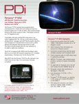
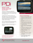
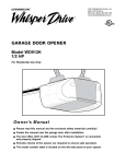
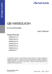
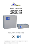
TRICODE® TCR2 DUAL
CHANNEL RECEIVER
®
USED FOR TCR1 AND TCR2
WARNING
WARNING
SPECIFICATIONS
CAUTION
WARNING
Output Rating: 5 Amps 28Vac/Vdc Max.
Power: 12Vdc or 18 to 34Vac/Vdc, @ 30ma
RF Frequency: 300 or 310 MHz
Accessory Transmitters: TC1, TC2 and TC4
To prevent possible SERIOUS INJURY or DEATH from electrocution:
• Be sure power is NOT connected BEFORE installing the receiver.
To prevent possible SERIOUS INJURY or DEATH from a moving
gate or garage door:
The TriCode® digital receivers are designed for use with automatic
garage/gate operators and access control systems. All TriCode®
products may be matched with Linear/Delta-3TM, Multi-CodeTM, and
StanleyTM radio products which may already be installed.
The TriCode® radio format provides a potential of 1024 different
digital codes. For Linear/Delta-3TM compatible products, 256
different digital codes are available. The codes are set using
10-position DIP switch system.
• ALWAYS keep transmitters out of reach of children. NEVER permit
children to operate or play with remote control transmitters.
• Activate gate or door ONLY when it can be seen clearly, is properly
adjusted, and there are no obstructions to door travel.
• ALWAYS keep gate or garage door in sight until completely closed.
NEVER permit anyone to cross path of moving gate or door.
NOTICE: To comply with FCC and or Industry Canada (IC) rules, adjustment or modifications of
this receiver and/or transmitter are prohibited, except for changing the code setting or replacing
the battery. THERE ARE NO OTHER USER SERVICEABLE PARTS.
Tested to Comply with FCC Standards FOR HOME OR OFFICE USE. Operation is subject to the
following two conditions: (1) this device may not cause harmful interference, and (2) this device
must accept any interference received, including interference that may cause undesired operation.
U.S. Patent 6,915,146
POWER SWITCH SETTINGS
NOTE: To avoid the possibility of duplicating codes in adjacent
systems, all transmitters and receivers should be re-coded prior
to operation. Unless using maximum number of codes the
following four codes should not be used:
· All DIP Switches ON
· All DIP Switches OFF
· DIP Switches alternating ON/OFF
· DIP Switches alternating OFF/ON
Power Supply Selection Setting
The TriCode® receiver is factory set for 24 volt power input if
12 volt is required.
Remove back cover of receiver by removing screws. Set jumper
to the 12 volt setting (Figure 1).
Receivers should be installed at least 5' apart to avoid cross-talk.
After completing installation, operate transmitter outside of
building to make certain the chosen DIP switch setting does not
operate with nearby garage door operators and/or security
systems. If so, select another DIP switch setting and check the
coded signal again. Repeat as necessary.
RECEIVER MOUNTING
Mount receiver to wall using #6 hardware (not provided).
Hardware used will depend on mounting application. Refer to
Figure 1 for receiver mounting hole locations.
Figure 1
Back View
JUMPER
(P3)
Mounting Holes
24V
P3
24V
12V
P3
2
12V
OUTPUT RELAYS & CONFIGURATION SWITCH SETTINGS
Setting Output Relay Mode
The TriCode® receiver is factory set for momentary relay output
“MNT”.
Setting the Configuration Switch
The TriCode® receiver is factory set for Linear/Delta-3TM.
Locate the configuration switch and set it to the desired RF mode
of operation (Figures 2 and 3). Modes are as follows:
Linear/Delta-3TM: works with all “Linear/Delta-3TM” transmitters
transmitted at 310 MHz using 8-bits ID system.
MultiTM: works with all “Multi-CodeTM” transmitters transmitted at
300 MHz using 10-bits ID system.
StanleyTM: works with all “StanleyTM radio” transmitters
transmitted at 310 MHz using 10-bits ID system.
• Momentary mode: The output relay will be on for .5 seconds
before turning off.
• Constant pressure mode: Output relay is continuously on
while receiving matching/valid ID code from transmitter. The
output relay will turn off immediately once receiver does not
receive a matching/valid ID code from the transmitter
(Figure 3).
NOTE: If constant pressure mode is desired, open front cover
and move mode jumper from “MNT” to “CST” (Figure 2).
Figure 2
Configuration
Switch
Delta-3/ Linear
Multi-Code
Stanley
TM
Figure 3
Relay
CH2-mode
Relay
CH1-mode
CH1
MODE
CST MNT
CST MNT
CH2
MODE
LINEAR
MULTI
STAN
CH1 CST
MODE
MNT
CST
MNT
CH2
MODE
3
Configuration
Switch
TM
TM
TM
Delta-3/Linear
TM
Multi-Code
Stanley TM
TM
TM
TM
310 MHz
300 MHz
310 MHz
DIP SWITCH SETTINGS & POWER CONNECTIONS
Setting DIP Switch
The TriCode® Receiver DIP switch CH1 is factory set OFF (1-10)
and CH2 is factory set ON (1-10).
Locate the 10 position DIP switch. If this is a new installation
using TriCode® transmitters, randomly set switches matching
those of the transmitter. Never use factory settings. If receiver is
used with Linear/Delta 3TM, Multi-CodeTM or StanleyTM transmitters,
match the receiver DIP switch to the above transmitters. Some
transmitters may use toggle switches and it may be difficult to
determine on & off. If so, try reversing the setting on the
TriCode® DIP switch (Figures 4 and 5).
Power Supply and Relay out Connections
There are six wires exiting the housing (Figure 6):
RED & BLACK - POWER INPUT
BROWN & BLUE - CHANNEL 1 RELAY OUTPUT
WHITE & GREEN - CHANNEL 2 RELAY OUTPUT
Power
Supply
12V/24V
Black
NOTE: In 'LINEAR/DELTA-3TM' mode (8-bits system) the last 2
bits (DIP #9 & 10) settings are ignored. They can be left in either
‘ON’ or ‘OFF’ settings.
Figure 4
Multi/ Stanley
(1 Thru 10)
Linear/ Delta-3
(1 Thru 8)
DIP
Switch
O
N
1
2
3
4
5
6
Brown
Relay
Output
Ch1
White
TM
7
8
Relay
Output
Ch2
9 10
DIP
Switches
Channel 2 DIP Switch
O 1 2 3 4 5 6 7 8 9 10
N
Channel 1 DIP Switch
O 1 2 3 4 5 6 7 8 9 10
N
Figure 5
2
3 4
5
6
7
8
9 10
O1
N
2
3 4
5
6
7
8
9 10
For installation and service information please
call our toll free number:
1-800-528-2806
or contact us through the web at
www.chamberlaingroup.com
01-17468D
Blue
TM
O
F
F
O1
N
Red
Figure 6
© 2007, The Chamberlain Group, Inc.
All Rights Reserved
Green