1
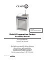
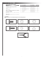
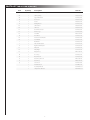
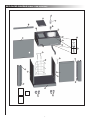
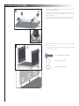
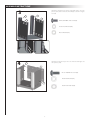
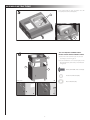
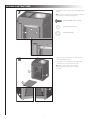
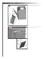
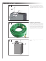
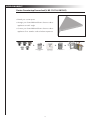
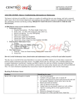
Attention:
Garden hose NOT included.
Sink & Preparation Centre
Assembly Manual
85-1140-8 (A01201)
Limited 3-Year Warranty
Read and save manual for future reference.
Assemble your grill immediately.
Missing or damaged parts should be
claimed within 15 days of purchase.
Call the Centro Hotline at 1-877-707-5463.
Manual Revision #:
120407
H E AV Y A R T I C L E N E E D S 2 TO L I F T
THIS MANUAL MUST REMAIN WITH THE PRODUCT AT ALL TIMES
To ORDER non-warranty replacement parts or accessories,
or to register your warranty, please visit us on the web at
www.centrobbqs.com.
CAUTION
DANGER
Sharp edges. Wear gloves when assembling
your grill.
1. If you smell Gas:
a. Shut off gas to the appliance
b. Extinguish any open flame
c. Open lid
d. If odor continues, keep away from
the appliance and immediately
call your gas supplier or your
fire department
CAUTION
Read and follow all safety statements,
assembly instructions, and use and care
directions before attempting to assemble
and cook.
INSTALLER OR ASSEMBLER/CONSUMER
This manual should be kept with the BBQ at
all times.
WARNING
Failure to follow all of the Manufacturer’s
instructions could result in hazardous fires,
explosions, property damage, or serious
personal injury or even death.
2. Do not store or use gasoline or other
flammable vapours and liquids in the
vicinity of this or any other appliance.
3. An LP cylinder not connected for use shall
not be stored in the vicinity of this or any
other appliance.
4. Requires two people to complete the
assembly process.
5. Beware of sharp edges.
Follow all leak check procedures carefully
prior to operation of barbecue, even if grill
was dealer assembled. Do not try to light
this barbecue without reading the Lighting
Instructions section of this manual.
T H I S B A R B E C U E I S F O R O U T D O O R U S E O N LY
CONTAC T C ALL CE N T R E IF ANY PARTS AR E M IS S IN G
ASSEMBLY INSTRUCTIONS
TOOLS NEEDED FOR ASSEMBLY
• #2 Phillips screwdriver (long and short)
• ¼” Slotted screwdriver (long and short)
• Adjustable wrench
• Pliers
• Rubber Mallot
Before assembling the barbecue, read these
instructions carefully.
Assemble the barbecue on a flat, clean surface.
Grill is heavy.
No. Description
Part Number
1
1/4"-20UNC×13 Screw
20120-13013-250
10
2
ø7 Flat Washer
41400-07000-250
10
3
ø7 Lock Washer
40300-07000-250
10
4
NO.10-24UNC x10 Screw
20124-10010-250
14
5
ø5 Lock Washer
41400-05000-250
14
6
ø5 Washer
40300-05000-250
14
7
Wrench
G413-0032-9082
1
Notes: Do not fully tighten all the nuts during this
initial stage.
Caution:
Sheet metal can cause injury. Wear gloves when installing the grill.
#1. ¼” - 20UNC×13 Screw (x10)
#2. ø7 Flat Washer (x10)
#3. ø7 Lock Washer (x10)
#4. NO.10-24UNC x10 Screw (x14)
#5. ø5 Lock Washer (x14)
#6. ø5 Washer (x14)
#10. Wrench (x1)
1
Quantity
PARTS LIST FOR 85-1140-8 (A01201)
Item
Quantity
Description
Part No.
A1
1
Main Cart Frame Assembly
A012-0100-01
A2
1
Sink Assembly
A006-0900-01
A3
1
Upper Back Panel
A012-0008-01
B
1
Connector
A006-0018-01
C
1
Faucet
A006-0009-01
D
1
Cutting Board
A012-0002-01
E1
1
Sink Strainer
A006-0028-01
E2
1
Sink Hose
A006-0022-01
F1
1
Condiment Holder
A012-0005-01
F2
1
Cuisine Logo
A012-0006-01
F3
1
Towel Bar
G502-0016-01
G
1
Front Brace
A012-0001-01
H1
1
Handle for Trash Basket
A012-0014-01
H2
1
Trash Basket
A012-0013-01
I
1
Back Panel
A012-0007-01
J
1
Left Side Panel, Cart
A012-0200-01
K
1
Right Side Panel, Cart
A012-0300-01
L1
1
Pillar, Left
A012-0600-01
L2
1
Pillar, Right
A012-0700-01
L3
2
Magnet Assy
G401-0052-01
M
1
Door Assy
A012-3000-01
N
1
Bottom Shelf
A012-0500-01
O
2
Caster Assy W/ Lock
G401-0061-01
P
2
Caster Assy
G606-0027-01
Q
1
Joint Hook
A012-0016-01
1
Hardware Pack
A012-B001-01
1
Assembly Manual
A012-M001-01
1
Safety & Care Manual
G617-M001-02
2
EXPLOADED DIAGRAM FOR 85-1140-8 (A01201)
D
C
G
B
A3
A2
A1
E1
I
F1
F3
F2
E2
H1
Q
H2
L3
L3
J
M
K
L2
L1
N
Manual
Hardware
Pack
Safety & Care
Manual
P
O
3
ASSEMBLY INSTRUCTIONS
1
Separate the 2 different types of wheels, 2 locking wheels
(O) and 2 regular wheels (P).
P
Attach the locking wheels (O) to the back of the bottom
shelf (N) and the regular wheels (P) to the front of the
bottom shelf (N).
To secure the 4 wheels, hand tighten first. Then, tighten
further using the wrench provided in the hardware pack.
O
N
2
Ensure that the wheels are firmly locked in the “ON” position
before continuing.
J
Assemble the left side panel (J) and the right side panel (K)
to the bottom shelf (N).
K
#1 1/4"-20UNCx13 Screw(X6)
#2 ø7 Flat Washer(X6)
#3 ø7 Lock Washer(X6)
N
Front view
4
ASSEMBLY INSTRUCTIONS
3
Back view
Attach the left pillar (L1) and the right pillar (L2) to the side
panels (J & K) and to the bottom shelf (N), as shown in Figure
A and B.
L1
L2
J
K
#4 No.10-24UNC x10 Screw(X6)
#5 ø 5 Lock Washer(X6)
#6 ø 5 Washer(X6)
A
4
B
Attach the back panel (I) to the rear of the left and right cart
side panels (J & K).
J
I
#1 1/4"-20UNCx13 Screw(X4)
#2 ø7 Flat Washer(X4)
K
#3 ø7 Lock Washer(X4)
Front view
5
ASSEMBLY INSTRUCTIONS
5
From underneath the sink cart, attach the sink
hose (E2) to the sink assembly (A2).
E1
E2
Underside of the main cart frame.
6
THIS STEP REQUIRES 2 OR MORE PEOPLE.
DO NOT ATTEMPT ALONE. EXTREMELY HEAVY!
a. Position the main cart frame (A) onto the cart
assembly, as shown in Figure A.
A3
b. Use the hardware to connect both parts, on the
left and right sides, at the four points indicated
in Figure B.
K
I
#4 No.10-24UNC x10 Screw(X6)
#5 ø 5 Lock Washer(X6)
A.
Back view
B.
B.
6
#6 ø 5 Washer(X6)
ASSEMBLY INSTRUCTIONS
7
Attach the front brace (G) to the left and right pillars
(L1 & L2).
TIP: One person should align the left side, while the
second person assembles the right side.
#4 No.10-24UNC x10 Screw(X2)
#5 ø 5 Lock Washer(X2)
G
L1
L2
#6 ø 5 Washer(X2)
Front view
8
a. Locate the door anchor pins on both the left
and right pillars (L1 & L2).
b. Locate the holes on the bottom of the door (M).
Insert the door anchor pins into the door.
Tip: push in on the door anchor pin with
something solid so that the door can slide
into place.
L1
L2
M
L2
L1
7
ASSEMBLY INSTRUCTIONS
9
Slide the trash basket (H2) down the rails that are
located behind the door (M) as shown.
H2
M
10
Insert the handle for the trash basket (H1) into the
back of the trash basket (H2).
M
H1
H2
M
8
ASSEMBLY INSTRUCTIONS
11
a. Remove washer and adaptor from faucet (C).
b. Insert faucet (C) through the main cart frame
(A). Tighten in position using the washer and
adaptor removed.
C
Washer
Adapter
A3
B
12
A garden hose is required for this step.
To attach the garden hose to the unit: There are
two pieces to the Connector (B). Separate the two
pieces to slide a cut garden hose through the collar.
Then insert the end of the garden hose to the
Connector. Now screw the collar to the other part
of the Connector to fasten the garden hose. Finally
attach the two pieces of the Connector together.
13
Place the cutting board (D) on the main cart
frame (A).
D
A
9
NOW AVAILABLE!
Centro Countertop Corner Leaf (# 85-1147-4/ A01301)
Step 1
o Extend your counter space
Attach th
to (A) by
and #3 (
o Arrange your Centro BBQ and Centro Cuisine outdoor
appliances at a 45° angle
o Connect your Centro BBQ and Centro Cuisine outdoor
appliances for a seamless outdoor kitchen experience.
Design inspired,
Chef admired
2800
3800
5800
4800
6800
+
+
Sink&
& Preparation
Centre
Sink
Preparation
Centre
EASY CLEAN GREASE
COLLECTION SYSTEM
Completely removable
lower casting and grease
tray.
PRECISION PORTED
BURNERS
U-shaped stainless steel
grill burners accurately
deliver up to 14,200 BTU
each.
S
SURE-START IGNITION
E
Enjoy the endurance
a
and reliability.
+
Counter Top
Corner Leaf
Counter Top Corner Leaf
Expand the possibilities with Centro Cuisine Series
10
PERFORMANCE AND
DURABILITY
Cast iron cooking grates,
warming rack and heat
plates. Durability and
performance.
=
Breakfast Centre
Breakfast
Centre
www.centrobbqs.com


![[CEN 061] 85-1250-6 Manual F](http://vs1.manualzilla.com/store/data/006313003_1-7ea7364065414a96460e03d14822bf45-150x150.png)