1
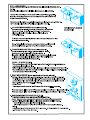
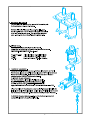
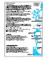
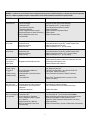
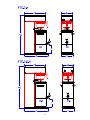
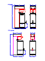
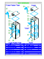
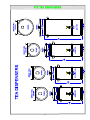
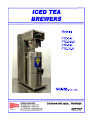
PHASE HZ
WATTS NO. OF
RECEPTACLE
AMPS
KW HEATERS
NEMA NO.
POWER CORD
CIRCUIT
BREAKER AMPS
5-15R
5-15P [2 WIRES+GND]
15A
12.5
6-20R
6-20P [2 WIRES+GND]
20A
25
6-30R
6-30P [2WIRES+GND]
30A
MODEL NO.
VOLTS
FTC-3-N, FTC-3.5-N
FTC-5-N,
120
1
60
1.75
1
15
FTC-5-N, FTC-10-N
240
1
60
2.80
1
FTC-10-N
240
1
60
5.60
2
ELECTRICAL SPECFICATIONS
* Export 220 Volts, 2.40 KW
OPERATING ENVIRONMENTAL TEMPERATURE:
Do not store unit in temperatures of 32° F or below with tank filled with water. Make sure tank is drained and lines purged to avoid damage.
NOTE: The appliance is not suitable for unsupervised use by young children or aged or infirm persons, according to national standards.
If the main power supply cord is damaged, it must be replaced by the manufacturer or its service agent or a similar qualified person in order
to avoid a hazard.
UNPACKING AND ASSEMBLY:
The machine is shipped with a set (4) adjustable leveling feet already mounted, (1) brew funnel, (1) brew-thru cover, and (1) water inlet fitting and
(1) Operating and Service Manual.
WATER INLET CONNECTION:
HIGHLY RECOMMENDED: A water shut-off valve and a water filter, preferably a combination charcoal/ phosphate filter, to remove odors and
inhibit lime and scale build up in the machine.
Note: In areas with extremely hard water, a water softener must be installed in order to prevent a malfunctioning of the equipment and in order not
to void the warranty.
The tea dispenser is equipped with a ¼" flare water inlet fitting which is located in the back of the unit.
Connect the ¼" dia. Copper waterline to the ¼" flare water inlet fitting of the valve.
This equipment is to be installed to comply with the applicable federal, state, or local plumbing codes having jurisdiction.
In addition:
1. A quick disconnect water connection or enough extra coiled tubing (at least 2x the depth of the unit) so that the machine can be moved for
cleaning underneath.
2. An approved back flow prevention device, such as a double check valve to be installed between the machine and the water supply.
3. For use of machine outside the United States of America, connection to water supply mains should comply with the national “Model Water
Byelaws”.
The brewer must be connected to a cold water supply with an operating pressure of 20psi minimum and 90psi maximum from a ½ in. supply line.
If pressure should exceed 90psi, install a pressure regulator to reduce the operating pressure to 50psi. Use ¼ inch copper tubing for installation of
less then 25 ft. and 3/8 copper tubing for more then 25ft from a ½ in cold water supply line.
Install the water inlet fitting provided onto the inlet valve located in the back of the unit. Do not over tighten.
Connect the ¼” copper waterline to the ¼" flare water inlet fitting on the valve.
NOT RECOMMENDED! The uses of a saddle valve to hook up the brewer since most of them restrict the water flow causing inconsistent brew
batches.
2
Note: In areas with extremely hard water, a Water Softener must be installed to prevent a
malfunctioning of the equipment due to high lime and mineral buildup. Not doing so it will
void the warranty.
COMPLIANCES! This equipment to be installed to comply with the Basic Plumbing Code of the
Building Officials and Code Administrators International, Inc. (BOCA) and of the Food and Drug
Administration (FDA.)
INITIAL SET-UP,
1 .Make sure unit is disconnected from power source.
2..Remove top cover and make sure that heater switch is in the OFF position. This will prevent Heater Damage
due to lack of water in the tank.
3. Plug the brewer into a power source.
4. Water will flow into the tank and will stop when the tank is fully primed ( 4-5 minutes)
Note: This process Is automatic and is controlled by the Level Control Board and the Level Control Sensor
plugged into the top of the Tank.
5. Flip the Heater Toggle Switch to the ON position. This activates the heater . Allow 15-20 min. heat up time.
6. Unplug the brewer and Replace the top cover.
7. Re-connect the brewer and test run the unit by going through a Brew Cycle .
NOTE:
The machine is equipped with a Low Temperature Lockout system and will not brew until the hot water tank is
filled with water and has reached the proper brew temperature of 197-203°F.
Insert the Brew Funnel and position empty Dispenser under it.
Go through one Brew cycle to make sure unit is operating properly.
Note: To test the brew cycle with cold water, flip Heater Switch to OFF position. This deactivates the
temperature lockout and allows speedier testing.
Tea Brewing Procedures.
The Brewers are Factory preset to deliver the correct amount of hot water for best extraction of Hot Tea
Concentrate and Cold Water Dilution. See Flavor Chart. Different Tea Blends might require some secondary
adjustments of Hot and Cold water ratios in order to achieve their desired flavor profiles. This is easily
accomplished by adjusting the Cold and Hot Brew Timers located inside the top. See instructions under
Adjustments (for qualified Service Personnel only)
FLAVOR CHART
MODEL
HOT WATER
COLD WATER
DELAY
TEA BAG SIZE
FTC-3-N, FTC-3.5-N
0.78 gal. [3 liters] in 3 minutes
2.75 gal. [10 liters]
1 ½ Min
3 oz
FTC-3-N, FTC-3,5-N
(Special Order)
0.78 gal. [3 liters] in 3 minutes
2.75 gal. [10 liters]
5 Min
3 oz
FTC-5-N
1.30 gal. [5 liters] in 5 minutes
3.70 gal. [14 liters]
1 ½ Min
4 oz
FTC-10-N
2.6 gal. [10 liters] in 10 minutes
7.50 gal. [28 liters]
1 ½ Min
(2) 4 oz or
(3) 3 oz
3
Tea Brewing Instructions
CAUTION:
Operate with care.
Tea Brewer dispenses HOT WATER and HOT TEA that can cause serious burns.
1. Start each brew cycle with a clean brew funnel and a clean empty tea dispenser.
2. Place a tea bag into the funnel and slide the funnel into the funnel rails until it stops.
3. When the Green Brew Switch Light comes on, press and release the Brew Button.
NOTE:
This tea brewer will not brew until the pre-set brew temperature (197-203° F) is reached.
4. Allow approximately 3 minutes for the tea concentrate to stop dripping from the Funnel tip.
5. Carefully remove Brew Funnel and discard the used tea bag ONLY AFTER all visible dripping has
stopped.
4
5
6
7
SANITIZING:
All food dispensing units should be sanitized periodically. All parts to be sanitized must be cleaned first.
To prepare a sanitizing solution:
ADD 2 TSP. OF LIQUID CLOROX BLEACH (5.25% CONCENTRATION) TO 1 GALLON OF WATER AT ROOM TEMPERATURE (70° - 90°F).
Soak all parts for a minimum of 3 min. in the sanitizing solution.
Note: Always start with an unopened bottle of Clorox Bleach since the solution from an opened bottle has a short life span.
Let all sanitized parts drain and dry naturally. DO NOT WIPE THEM DRY.
Before using the sanitized unit (or parts) with food stuffs, rinse all parts thoroughly with water.
CARE FOR STAINLESS STEEL:
Stainless Steel surfaces that come in contact with food substances, MUST BE CLEANED EVERY DAY.
WHEN CLEANING STAINLESS STEEL, ONLY A pH NEUTRAL CLEANER IS TO BE USED.
Use nylon or brass brushes (not steel wire brushes) for removing food deposit.
Many food products contain acids, alkalis, or other substances which corrode Stainless Steel.
8
TROUBLESHOOTING GUIDE
WARNING: To reduce the risk of electrical shock unplug the dispenser power cord before repairing or replacing any internal components
of the unit.. Before any attempt to replace a component be sure to check all electrical connections for proper contact
PROBLEM
PROBABLE CAUSE
REMEDY
1
Brewed Cold Tea.
a) Heater Switch OFF.
b) Run out of hot water
c) Thermostat is OFF.
d) Loose electrical connection.
e) Thermostat is defective.
f) Hi-Limit Temperature Switch is tripped.
g) Bad Heating Element or Heater is burned out.
h) Bad low temperature cutout circuit.
Contactor/Relay
a) Turn Heater Switch ON.
b) Allow time for water in tank to heat after filling.
c) Set Thermostat at 197°F [to max. position].
d) Check all electrical connections for contact.
e) Replace Thermostat.
f) Replace the Hi-limit Temperature Switch..
g) Replace Heater.
h) Replace Contactor/ Relay.
2
Tea too weak.
a) Not enough Tea in the brew funnel.
b) Water flow too low.
c) Brew time is too short.
d) Water is too cold.
a) Put more Tea in the brew funnel [see chart]
b) Check flow [should be .26 gal /min.] Replace Dispense Valve.
c) Adjust hot water timer to 3 min. max.
d) Adjust Thermostat to 197°F [to max. position]
3
Tea too strong.
a) Too much tea in the brew funnel.
b) Water flow is high
c) Brew time is too long.
d) Water is too hot.
a) Put less Tea in the brew funnel [see chart]
b) Check flow [should be .26 gal /min.] Replace Dispense Valve.
c) Adjust hot water timer to 3 min. 197°F [to max. position]
d) Adjust Thermostat to 197°F [to max. position]
4
a) Leaking Water Inlet Valve.
Water keeps dripping
or running from
b) Clogged/ stuck Water Dispense Valve
dilution nozzle.
a) Clean/check fittings of Water Inlet Valve.
Replace Water Inlet Valve if needed. See ”Water Inlet Valve Test”
b) Clean/unclog Water Dispense Valve.
Replace Dispense Valve if defective.
5
No water is going
into tank at all.
or
No water is coming
from dilution nozzle
a) Check Water Inlet Valve. Replace if necessary.
See “Water Inlet Valve Test”
b) Test High-Level Float Switch. See “High-Level Float Test”
c) Check Probe. Replace if necessary.
d) Check The Water Level Controls. Replace if necessary.
a) Water Inlet Valve malfunction.
b) Hi-Level Float Switch malfunction.
c) Probe malfunction.
d) Solid State Water Level Controls board
malfunction.
e) Timer malfunction.
e) Check Timer: Time dispensing time vs. set time on Timer.
Replace if necessary.
6
a) Water Level Probe malfunction.
Water will not stop
b) Solenoid (Water Inlet Valve) malfunction.
flowing into water tank. c) Solid State Water Level Control board
malfunction.
d) Float Switch malfunction.
a) Check Level Control Probe. Replace if necessary. See “ProbeTest”.
b) Check Solenoid. Replace if necessary.
c) Check The Water Level Controls. Replace if necessary.
7
a) Heater Switch is OFF.
Water is not heating up b) Thermostat is OFF.
in the water tank.
c) Loose connection on Thermostat.
d) Hi-Limit Temperature Switch is tripped
or it is defective.
e) Heater is burned out or defective.
h) Bad Low Temperature Cutout Circuit.
Contactor/Relay.
a) Turn Heater Switch ON.
b) Turn Thermostat ON. Turn Thermostat Knob Clockwise.
c) Make sure all wires and ring terminals on the thermostat are tight.
d) Reset the Hi-Limit Button, If heater still does not work,
replace the Hi-limit Temperature Switch (see Item 6 in Tank ill.).
e) Replace the Heater.
h) Replace Contactor/Relay. See item 2 of Description of Components.
d) Replace Float Switch.
9
10
11
12
13
14
15