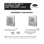
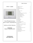
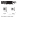
1
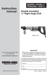
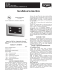
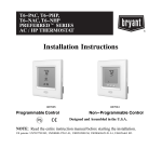
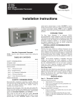
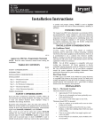
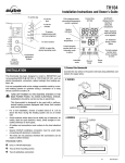
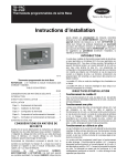
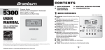
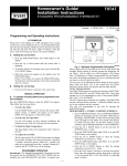
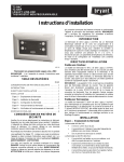
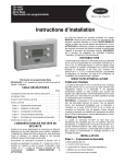
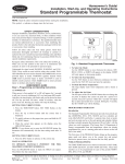
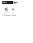
TB---PAC
TB---PHP
Base Series Programmable Thermostats
Installation Instructions
Designed and Assembled
in the USA.
US patents: US20060165149 A1, USD578026 SI, US6205041 B1
included in literature and attached to the unit. Consult local
building codes and the current editions of the National Electrical
Code (NEC) NFPA 70.
In Canada, refer to the current editions of the Canadian Electrical
Code CSA C22.1.
.
Recognize safety information. This is the safety--alert symbol
When you see this symbol on the unit and in the instructions or
manuals, be alert to the potential for personal injury.
Understand the signal words DANGER, WARNING, and
CAUTION. These words are used with the safety--alert symbol.
DANGER identifies the most serious hazards which will result in
severe personal injury or death. WARNING signifies a hazard
which could result in personal injury or death. CAUTION is used
to identify unsafe practices which may result in minor personal
injury or product and property damage. NOTE is used to highlight
suggestions which will result in enhanced installation, reliability, or
operation.
INTRODUCTION
SAFETY CONSIDERATIONS . . . . . . . . . . . . . . . . . . . . . . . . . 1
INTRODUCTION . . . . . . . . . . . . . . . . . . . . . . . . . . . . . . . . . . . 1
There are two Base Series programmable thermostat models, one
for AC applications and one for HP applications. Both are dual
powered, operating from either 24VAC or two alkaline AA
batteries. Configuration and program schedules are stored in
non--volatile memory, preserving this information during power
loss and battery removal. Features include simplified 5/2 day
programming, large backlit display, and modern styling.
The AC model provides one stage of heating and one stage of
cooling.
The HP model provides two stages of heating and one stage of
cooling.
INSTALLATION CONSIDERATIONS . . . . . . . . . . . . . . . . . . . 1
INSTALLATION CONSIDERATIONS
A07107
Base Series Programmable Thermostat
NOTE: Read the entire instruction manual before starting the
installation
TABLE OF CONTENTS
PAGE
INSTALLATION . . . . . . . . . . . . . . . . . . . . . . . . . . . . . . . . . . . . 2
Step 1 — Thermostat Location . . . . . . . . . . . . . . . . . . . . . . . . 2
AC Operation
Step 2 — Install Thermostat . . . . . . . . . . . . . . . . . . . . . . . . . . . 2
For 24VAC operation, both the R and C wires must be connected
to the 24VAC power source. Batteries are not needed.
Step 3 — Set Thermostat Configuration . . . . . . . . . . . . . . . . . 3
Battery Operation
Step 4 — Understand Thermostat Operation . . . . . . . . . . . . . . 3
When batteries are used, the common (C) connection is not needed,
saving a wire, and eliminating 24VAC operation. The thermostat
continues to operate in the event of a power failure. Battery life is
expected to be one year. A “low battery” reminder tells the
homeowner when it is time to replace the batteries. When
connected without the common wire, the thermostat will not
operate without batteries. Continuous back--lighting is not
available.
Step 5 — Check Thermostat Operation . . . . . . . . . . . . . . . . . . 4
WIRING DIAGRAMS . . . . . . . . . . . . . . . . . . . . . . . . . . . . . . . . 4
SAFETY CONSIDERATIONS
Improper installation, adjustment, alteration, service, maintenance,
or use can cause explosion, fire, electrical shock, or other
conditions which may cause death, personal injury, or property
damage. Consult a qualified installer, service agency, or your
distributor or branch for information or assistance. The qualified
installer or agency muse use factory--authorized kits or accessories
when modifying this product. Refer to the individual instructions
packaged with the kits or accessories when installing.
Follow all safety codes. Wear safety glasses, protective clothing,
and work gloves. Have a fire extinguisher available. Read these
instructions thoroughly and follow all warnings or cautions
Both Battery and AC Operation
If both batteries and 24VAC operation are used (batteries installed
and the common wire connected), and indefinite clock operation
are provided, the battery will be used only during AC power loss,
extending battery life to nearly its shelf life.
A jumper has to be properly set for backlight operation. J2 should
be set in the “AC” position when the thermostat is operated from
24VAC. J2 should be set in the “BAT” position when the
thermostat is operated from batteries. The thermostat will continue
to operate if J2 is not in the correct position or not connected.
However, the backlight will not operate.
INSTALLATION
IMPORTANT: Install batteries last to ensure proper thermostat
mounting and latch engagement.
Step 1 — Thermostat Location
TB -- PAC / TB -- PHP
Thermostat should be mounted:
S Approximately 5 ft (1.5m) from floor.
S Close to or in a frequently used room, preferably on an inside
partitioning wall.
S On a section of wall without pipes or duct work.
6. Secure back plate to wall with 2 anchors and screws
provided making sure all wires extend through hole in
plastic.
NOTE: Anchoring the back plate will maximize proper mounting
plate flatness and allow latch to fully engage.
7. Connect wires to proper terminal location on backplate.
8. Push any excess wire back into wall. Seal hole in wall to
prevent air leaks. Leaks can affect thermostat operation.
Any excess wire left inside thermostat casing may also affect thermostat operation by interfering with airflow across
the temperature sensor.
9. Set the thermostat front housing into the (2) latches
(notches) on the bottom of the back plate.
Thermostat should NOT be mounted:
S Close to a window, on an outside wall, or next to a door leading
to the outside.
S Exposed to direct light and heat from the sun, a lamp, fireplace,
or other heat--radiating object which may cause a false reading.
S Close to or in direct airflow from supply registers and return--air
grilles.
S In areas with poor air circulation, such as behind a door or in an
alcove.
Step 2 — Install Thermostat
IMPORTANT: Install batteries last to ensure proper thermostat
mounting and latch engagement.
A08429
10. Rotate the front housing forward and press on the faceplate
with thumbs near the Up/Down arrows on the right and the
“H/C” and fan symbols on the left side of the display. Do
this with a moderate amount of pressure.
WARNING
!
ELECTRICAL OPERATION HAZARD
Failure to follow this warning could result in personal injury
or death.
Before installing thermostat, turn off all power to unit. There
may be more than 1 disconnect. Lock out and tag switch with
a suitable warning label.
1. Turn OFF all power to HVAC unit.
2. If an existing thermostat is being replaced:
a. Remove existing thermostat from wall.
b. Disconnect wires from existing thermostat, one at a
time. Be careful not to allow wires to fall back into wall.
c. As each wire is disconnected, record wire color and
terminal marking.
d. Discard or recycle old thermostat.
!
A08430
11. If necessary, continue to rotate the front housing forward
and press to engage the top corner latches.
CAUTION
ENVIRONMENTAL HAZARD
Failure to follow this caution may result in environmental
damage.
Mercury is a hazardous waste and may be found in the old
thermostat. Federal regulations require that Mercury be
disposed of properly.
3. Separate front and back plastic assembly of thermostat.
4. Route thermostat wires through hole in mounting base.
Level mounting base against wall (for aesthetic value only,
thermostat need not be level for proper operation) and mark
wall through 2 mounting holes.
5. Drill two 3/16--in. (5mm) mounting holes in wall where
marked.
A08431
12. Snap thermostat together making sure assembly is secure.
13. Install the batteries.
2
Step 3 — Set Thermostat Configuration
Configuration options enable the installer to configure the
thermostat for a particular installation.
These are not presented to the homeowner and therefore must be
properly set by the installer. Following is a list of the options
available, an explanation of their function, and their factory default
settings. Not all numbers are used in the Base Series because not all
options are available in this series.
Configuration Options -- Summary:
Option 01 -- Equipment type
Option 03 -- Fahrenheit/Centigrade
Option 04 -- Fan (G) on with W output
Option 10 -- Reversing valve
Option 13 -- Room air temperature offset
Option 21 -- Keypad Lockout
Option 26 -- Minimum Cooling Setpoint
Option 27 -- Maximum Heating Setpoint
To Enter The Configuration Mode:
Press and hold the FAN key for about 10 seconds until the display
changes so that only two pairs of digits are showing. The
configuration number, now 01, will appear in the
setpoint/temperature location and the configuration setting will
appear in the clock location. The configuration number (left pair)
will be flashing which means it can be adjusted using the UP and
DOWN keys. To cause the opposite pair to flash (to be adjustable),
press the H/C key. Successive presses of the H/C key alternate
between the configuration number (left) and the configuration
setting (right). To exit the configuration mode, press the
HOLD/END key. If no key is pressed for 3 minutes, the
configuration mode will automatically exit, returning the
thermostat to normal operation.
Configuration Options -- Selection:
Option 01 -- Equipment type
Selections: with HP thermostat: HP, AC, PH, or PC
with AC thermostat: AC or PC
Meanings:
PH or PC selects PTAC units (Packaged Terminal Air
Conditioners) which are used in motel rooms and other rented
spaces. When this option is selected, the display shows only the
setpoint, not the room temperature. Also, the compressor
timeguard is disabled, allowing the compressor to turn on
immediately when a demand is established.
HP or PH controls 1 speed heat pump with 1 stage of aux heat.
AC or PC controls 1 speed air conditioner with one stage of heat.
Note that this option allows a HP thermostat to be converted to
control an AC system.
Option 03 -- Fahrenheit/Centigrade
Selections: F = Fahrenheit — This is default.
C = Centigrade.
Selects temperature display units.
Option 04 -- Fan (G) ON with W output
Selections: OF = G not energized with W — This is default.
ON = G energized with W.
This selection determines whether the fan (G) is to be ON or OFF
when the W (furnace or strip heat) is ON. Furnaces and fan coils
which manage their own blowers do not require a separate G
signal. Some auxiliary heaters require a separate G signal to operate
the blower when W is applied.
This option allows a HP thermostat to control an AC system.
Option 10 -- Reversing valve
Selections: C = reversing valve energized in cooling —This is
default.
H = reversing valve energized in heating — Only
appears in HP systems.
Option 13 -- Room Air Temperature Offset
Selections: ±5_F /3_C. Default is 0.
The number of degrees to be added to the displayed temperature to
calibrate or deliberately miscalibrate the measured room
temperature. This option is in _F even if Option 3 is set for _C.
Option 21 -- Keypad Lockout
Selections: ON, OF — Default is OF.
With OF selected, the keypad cannot be locked. With ON selected
the keypad will be locked and can be unlocked by simultaneously
pressing the UP and DOWN keys for 5 seconds. Once unlocked, it
will relock 2 minutes after the last keypad press. If any key is
pressed and the thermostat is locked, “loc” will be displayed in the
clock digits.
Option 26 -- Minimum Cooling Setpoint
Selections: 50_ to 90_F/10_ to 32_C — Default is 52_F/11_C.
Sets the lowest cooling setpoint available to the user.
Option 27 -- Maximum Heating Setpoint
Selections: 50_ to 90_F/10_ to 32_C — Default is 88_F/31_C.
Sets the highest heating setpoint available to the user.
Step 4 — Understand Thermostat Operation
Temperature Display
Thermostat will display room temperature until UP or DOWN
button is pressed. The words SET TEMP appear when these
buttons are pressed and the current setpoint is displayed. If no
buttons are pressed for 5 sec, the display will change back to show
room temperature.
Back lighting
Continuous back--lighting is not available. The backlight will come
on for 10 seconds after any button press. Without AC power and
when the battery is low, the backlight will remain off with button
presses.
Battery Indicator
A battery indication icon on the display shows nothing, half, or
low/no battery condition. If the battery is full or operation is from
AC power, no icon appears. Under battery operation, if the battery
is half full, a half full battery icon appears. As the battery depletes
below half, the icon remains at half, but the 10 second backlight
disappears. When the battery is absent or depleted, the display goes
blank except for an empty battery icon and all outputs are turned
off.
Timeguard Timer
A 5--minute timeguard is built into the thermostat immediately
upon power up, and any time the compressor turns off. The
compressor will not turn on until the timeguard has expired. The
timeguard affects only compressor operation. Pressing UP and
FAN buttons simultaneously will override the timeguard for 1
cycle. If PTAC operation (PH or PC) is selected under Option 1,
the timeguard timer is eliminated.
Cycle Timer
In normal heating and cooling operation the thermostat will not
allow more than 4 equipment cycles per hour (or 1 cycle every 15
minutes). Both the Y and W outputs have a 15--minute timer that
starts counting down when the output is turned on, (e.g., if Y
output is turned on for 9 minutes and then satisfies, it cannot turn
back on for another 6 minutes regardless of demand). However,
3
TB -- PAC / TB -- PHP
14. Turn ON power to unit.
On power up, depending on the thermostat model being used, the
LCD readout will display either AC for air conditioner model
(1--stage heat/1--stage cool) or HP for heat pump model (2--stage
heat/1--stage cool).
TB -- PAC / TB -- PHP
pressing UP and FAN buttons simultaneously or changing the
setpoint will override the timer for 1 cycle.
Minimum on Timer
Once the equipment has turned on, it will remain on for a
minimum of 3 minutes regardless of demand. However, the
equipment can turn off in less than 3 minutes if a change in
setpoint, or a change in mode occurs.
Staging Timer
If the thermostat is a heat pump model, it has 2--stage heat
capability. In normal operation there is a 15--minute delay between
the first and second stages of heat. The Y output will energize first,
then 15 minutes later, W is allowed to come on if the thermostat
determines it is not satisfying the demand.
However, if the heating demand is greater than 5_F/3_C, there will
be only a 30 second delay before bringing on W.
Auxiliary Heat Indicator
When operating a heat pump and either auxiliary heat or
emergency heat is active, an LCD display icon indicates this
condition.
A07821
Error Messages
If the room temperature sensor fails, two dashes (----) will appear in
the temperature display and all heating and cooling outputs will be
turned off. The thermostat must be replaced.
If the internal non--volatile memory fails, E4 will alternately flash
with the temperature on the display and all heating and cooling
outputs will be turned off. The thermostat must be replaced.
Step 5 — Check Thermostat Operation
Fan Operation
1. Press FAN button. This will start continuous fan operation.
FAN ON icon will turn on.
2. Press FAN button again. This will stop continuous fan operation. FAN ON icon will turn off.
Heating Operation
1. Press H/C button until HEAT is displayed.
2. Press UP button until LCD readout reads 3_F/2_C above
room temperature. Press UP and FAN buttons simultaneously to defeat timers. Heating system should begin to operate immediately.
3. For HP thermostats only, press H/C button until EMHT
(emergency heat) appears. Press UP and FAN buttons simultaneously to defeat timers. Emergency heating (W is ON,
Y is OFF) should begin immediately.
Cooling Operation
1. Press H/C button until COOL is displayed.
2. Press DOWN button until LCD readout reads 3_F/2_C below room temperature. Press UP and FAN buttons simultaneously to defeat timers. Cooling system should begin to operate immediately.
Table 1 shows the thermostat outputs for each available stage of
heating or cooling. It may be useful in checkout or
troubleshooting.
Table 1 – Outputs
EQUIPMENT
CONFIGURATION
OPTION #1
THERMOSTAT
TYPE
CONFIGURATION
COOL
STAGE 1
HEAT
STAGE 1
HEAT
STAGE 2
EM HEAT
AC, PC
AC, HP
Y, G
W
--- ---
--- ---
HP, PH
RVS = C
HP
Y, G, O/B
Y, G
Y, G, W
W
HP, PH
RVS = H
HP
Y,G
Y, G, O/B
Y, G, W, O/B
W
WIRING DIAGRAMS
A06566
A06567
Fig. 1 -- A/C Thermostat Typical Installation
Fig. 2 -- HP Thermostat Typical Installation
Edition Date: 05/09
Catalog No: TB---PAC ---7SI
Manufacturer reserves the right to change, at any time, specifications and designs without notice and without obligations.
Replaces: TB--- PAC--- 6SI
Copyright 2009 Carrier Corp. S 7310 W. Morris St. S Indianapolis, IN 46231
Printed in U.S.A.
4
TB---PAC
TB---PHP
Base Series Programmable Thermostats
Homeowner’s Guide
Designed and Assembled
in the USA.
A07107
Base Series Programmable Thermostat
SETTING TIME AND DAY
At Power Up
When power is first applied, AC or HP will appear for 5 seconds to
tell you it is an air conditioner (AC) or a heat pump (HP) model.
After this, the time display will flash to tell you the power has been
off.
Setting The Current Time:
1. Press the TIME/TEMP button. SET TIME flashes on the
display.
2. Press the UP or DOWN button until the correct time is displayed.
3. To quickly advance to the proper time, press and hold the
UP or DOWN button.
4. When the correct time appears on the display, press the
HOLD/END button.
NOTE: If you choose not to press the HOLD/END button, the
thermostat will automatically exit the time setting mode after 10
seconds.
Setting The Current Day:
1. Press the DAY button to advance to the correct day.
2. When the correct day appears on the display, press the
HOLD/END button.
MANUAL OPERATION
To Operate Manually (Without the Programmed
Comfort Schedule):
Press the HOLD/END button to make the HOLD icon appear.
Then follow the four steps below:
1. To Select the Mode:
Use the H/C button to move between the choices. OFF,
HEAT, COOL, or EMHT will appear on the display. EMHT
will only appear on heat pump models.
2. To Select the Fan Operation:
Use the FAN button to move between continuous fan (indicated by the FAN ON icon) and auto fan operation.
3. To Read the Room Temperature:
The large display reads room temperature until a button is
pressed.
4. To Adjust the Setpoint:
In normal operation, the large display shows room temperature. At the first press of the UP or DOWN button, the
large display shows the current setpoint and the SET TEMP
icon is turned on. Further presses of the UP or DOWN button adjust the setpoint upward or downward. Five seconds
after the last button press, the display returns to the room
temperature and the SET TEMP icon turns off.
PROGRAMMED OPERATION
Introduction
The Base Series Programmable Thermostat provides four periods
per day (MORNING, DAY, EVE, NIGHT) and two schedules per
week (MoTuWeThFr and SaSu). A separate time, heat setpoint,
and cool setpoint can be set for each period and schedule. Before
starting to actually program the thermostat, fill out Table 1 with the
values you wish to program. (The Energy Starr, US Department of
Energy recommended time and temperature values are already
programmed for you as a starting point and are shown on the left
side of the table.)
The first press of the PROGRAM button brings up the
programming mode and places you at morning of the current day
and period. Successive presses move you between the four daily
periods.
While Programming:
The TIME/TEMP button moves between three selections of SET
TIME, SET TEMP & HEAT, and SET TEMP & COOL. These
three numbers are to be programmed for each of the periods
MORNING, DAY, EVE, and NIGHT.
The DAY button moves between the weekdays, (MoTuWeThFr)
and the weekend (SaSu) selections. A different schedule may be set
for the weekdays and the weekend. You may exit programming at
any time by pressing the HOLD/END button.
TB -- PAC / TB -- PHP
Programming A Weekly Comfort Schedule:
settings to the programmed comfort schedule. Pressing
HOLD/END will not alter your programmed comfort schedule.
1. Press the PROGRAM button. The word PROGRAMMING
appears on the display and the words SET TIME flash on
the display. MoTuWeThFr or SaSu and the morning period
icons will appear on the display. The current mode (HEAT
or COOL) will also show. Use the DAY button to select
weekdays and the PROGRAM button to select MORNING.
2. Press the UP or DOWN button to set the start time for
MORNING ( 1) value in Table 1).
3. Press the TIME/TEMP button until COOL is on and SET
TEMP flashes on the display.
4. Press the UP or DOWN button to select the cooling temperature setpoint ( 2) value in Table 1).
5. Press the TIME/TEMP button until HEAT is on and SET
TEMP flashes on the display.
6. Press the UP or DOWN buttons to select the heating temperature setpoint ( 3) value in Table 1).
7. Press the PROGRAM button to advance to the next time
period. Enter time and temperature settings ( 4) through 12
in Table 1) for the periods DAY, EVE, and NIGHT by following items 2--6 above.
8. Press the DAY button to change between weekday and
weekend programming. To set the weekend schedule, repeat
items 2 through 7, entering values in 13) through 24) in
Table 1.
9. Press END/HOLD to exit the programming mode.
Method 2 — Temporary Override
At the first press of the UP or DOWN button, the current
temperature setting will appear on the display. Pressing the UP or
DOWN button again will temporarily change the setpoint as
needed. At the next programmed time, the programmed comfort
schedule will resume.
CHANGING BATTERIES
In some situations, two AA batteries are the power source for the
thermostat. If batteries are used with your equipment then they
should last about one year. As the batteries lose their power a
battery icon appears on the display. As the batteries get weaker, the
icon goes down to one black bar and then none. As the icon
becomes empty, you will begin to lose thermostat functions
because the batteries are losing their power. When the batteries are
completely dead, you won’t be able to use the thermostat.
When using batteries for power, we recommend you replace them
with two AA alkaline batteries. They are in a compartment under
the lid on top of the thermostat. You do not have to remove the
thermostat from the wall to replace the batteries. Simply open the
lid, lift out the batteries, and replace them like you would any other
battery operated device.
TROUBLESHOOTING
What if AUX HEAT appears on the display?
(Heat pump model only)
Modifying Your Weekly Comfort Schedule
If auxiliary heat is on, you will see AUX HEAT indicator in the
display. When it is on this means the system has determined that
it’s too cold outside for your heat pump to heat the house without
help, so it’s getting help from the electric heaters. This happens
automatically.
NOTE: This indicator does not mean there is a problem with your
system.
If you choose to change any of your weekly schedule, press
PROGRAM at any time. You will enter the programming schedule
at the present day, present mode, but always in the morning period.
You are ready to set the new starting time for the morning period.
One press of the TIME/TEMP button and you are ready to set the
new morning temperature. To set values for other periods, use the
PROGRAM button. To set values for other days, use the DAY
button. Press HOLD/END and you are finished.
What if E--Heat appears on the display?
If the heat pump is not working properly, you can manually turn
on the emergency heat for extra help in heating. You’ll know
there’s a problem if the house can’t seem to get warm when it’s
cold outside.
You want to avoid using emergency heat, though, because it’s the
most expensive option. And, of course, if you suspect a problem
with your heat pump, call your heating and cooling dealer
immediately.
Overriding Your Comfort Schedule
There are two ways to override your comfort schedule.
Method 1 — Manual Operation
By pressing the HOLD/END button to turn on the HOLD icon, the
thermostat will maintain the current temperature settings and
ignore the comfort schedule for an indefinite period of time. The
word HOLD will appear in the display. Press the HOLD/END
button a second time and the thermostat will return the temperature
Table 1 – Programming Table
ENERGY STAR
FACTORY DEFAULT VALUES
NEW COMFORT SCHEDULE
PERIOD
TIME
COOL
HEAT
MoTuWe ThFr
TIME
MORNING
6:00
A.M.
78_F
26_C
68_F
20_C
1)
2)
3)
13)
14)
15)
DAY
8:00
A.M.
85_F
29_C
60_F
16_C
4)
5)
6)
16)
17)
18)
EVE
5:00
P.M.
78_F
26_C
68_F
20_C
7)
8)
9)
19)
20)
21)
NIGHT
10:00
P.M.
82_F
28_C
60_F
16_C
10)
11)
12)
22)
23)
24)
COOL
2
HEAT
SaSu
TIME
COOL
HEAT
CARRIER CORPORATION
Limited Warranty for Thermostats, User Interfaces, Zoning and Related Accessories
FOR WARRANTY SERVICE OR REPAIR:
Contact the installer or a Carrier dealer. You may find the installer’s name on the equipment or in your Owner’s Packet. You can also find a
Carrier dealer online at www.carrier.com.
For help, contact: Carrier Corporation, Consumer Relations, P.O. Box 4808, Syracuse, New York 13221 Phone: 1--800--227--7437
PRODUCT REGISTRATION: You can register your product online at www.carrier.com.
Date of Installation ______________________________________ Installed by ____________________________________________
Name of Owner _________________________________________ Address of Installation ___________________________________
Carrier Corporation (hereinafter “Company”) warrants this product against failure due to defect in materials or workmanship under normal
use and maintenance as follows. All warranty periods begin on the date of original installation. If a part fails due to defect during the
applicable warranty period Company will provide a new or remanufactured part, at Company’s option, to replace the failed defective part at
no charge for the part. Alternatively, and at its option, the Company will allow a credit in the amount of the then factory selling price for a
new equivalent part toward the retail purchase price of a new Company product. Except as otherwise stated herein, those are Company’s
exclusive obligations under this warranty for a product failure. This limited warranty is subject to all provisions, conditions, limitations and
exclusions listed below and on the reverse (if any) of this document.
OWNER--OCCUPIED, RESIDENTIAL APPLICATIONS
This warranty is to the original purchasing owner and is transferable only to the extent and as stated in the Warranty Conditions and below.
The warranty period in years, depending on the part and the claimant, is as shown in the chart below.
Limited Warranty (Years)
Series
Infinity
Performance
Comfort
Base
Item
Original Owner
Subsequent Owner
User Interface & Smart Sensor
10* (or 5)
10** (or 5)
Zoning Board
10* (or 5)
10** (or 5)
Network Interface
10* (or 5)
10** (or 5)
Remote Access
10* (or 5)
10** (or 5)
Thermostat***
10* (or 5)
10** (or 5)
Zoning Interface & Smart Sensor
10* (or 5)
10** (or 5)
Zoning System
10* (or 5)
10** (or 5)
Thermostat
10* (or 5)
10** (or 5)
Zoning Board
10* (or 5)
10** (or 5)
Thermostat
5
5
*
If properly registered within 90 days, otherwise 5 years (except in California and Quebec and other jurisdictions that prohibit warranty benefits conditioned on registration, registration is not required to obtain longer warranty periods). See Warranty Conditions below.
** If properly transferred within 90 days, otherwise 5 years. See Warranty Conditions below. In California and Quebec and other jurisdictions that prohibit warranty benefits conditioned on registration, registration is not required for a transfer and all warranty periods for subsequent owners are five
years from original installation.
*** Applies only to Thermostats. Active electronic finished good accessories, such as the optional ExP module, have different warranty terms. See
product for details.
OTHER RESIDENTIAL APPLICATIONS (Apartments, Rental Properties, etc.)
The warranty period is five (5) years and is not transferable.
OTHER APPLICATIONS
This warranty is non--transferable. The warranty period is one (1) year on all such applications.
LEGAL REMEDIES: The owner must notify the Company in writing, by certified or registered letter to Carrier Corporation, Warranty
Claims, P.O. Box 4808, Syracuse, New York 13221, of any defect or complaint with the product, stating the defect or complaint and a specific
request for repair, replacement, or other correction of the product under warranty, mailed at least thirty (30) days before pursuing any legal
rights or remedies.
49004DP110
05/09
3
TB -- PAC / TB -- PHP
Model No./Serial No._____________________________________ Series (Infinity, Performance, Comfort, Base,) __________________
TB -- PAC / TB -- PHP
CARRIER CORPORATION
WARRANTY CONDITIONS:
1. To obtain the longer warranty periods as shown in the table under original owner, for the original purchaser, the product must be
properly registered at www.carrier.com within ninety (90) days of original installation. In jurisdictions where warranty terms conditioned on registration are prohibited by law, registration is not required and the longer warranty period shown will be apply.
2. Where a product is installed in a newly constructed home, the date of installation is the date the homeowner purchased the home from
the builder.
3. If the date of original installation cannot be verified, then the warranty period begins ninety (90) days from the date of product manufacture (as indicated by the model and serial number). Proof of purchase may be required at time of service.
4. The remainder of the first five years of warranty is freely transferable without registration. To obtain a transfer of the longer warranty
periods as shown in the table under subsequent owner, a subsequent owner must register the transfer at www.carrier.com within 90
days of the change in ownership and payment of a transfer fee. Not applicable in all jurisdictions. See website for details.
5. Product must be installed properly and by a licensed HVAC technician.
6. The warranty applies only to products remaining in their original installation location.
7. Installation, use, care, and maintenance must be normal and in accordance with instructions contained in the Installation Instructions,
Owner’s Manual and Company’s service information.
8. Defective parts must be returned to the distributor through a registered servicing dealer for credit.
LIMITATIONS OF WARRANTIES: ALL IMPLIED WARRANTIES AND/OR CONDITIONS (INCLUDING IMPLIED
WARRANTIES OR CONDITIONS OF MERCHANTABILITY AND FITNESS FOR A PARTICULAR USE OR PURPOSE) ARE
LIMITED TO THE DURATION OF THIS LIMITED WARRANTY. SOME STATES OR PROVINCES DO NOT ALLOW
LIMITATIONS ON HOW LONG AN IMPLIED WARRANTY OR CONDITION LASTS, SO THE ABOVE MAY NOT APPLY TO
YOU. THE EXPRESS WARRANTIES MADE IN THIS WARRANTY ARE EXCLUSIVE AND MAY NOT BE ALTERED,
ENLARGED, OR CHANGED BY ANY DISTRIBUTOR, DEALER, OR OTHER PERSON, WHATSOEVER.
THIS WARRANTY DOES NOT COVER:
1. Labor or other costs incurred for diagnosing, repairing, removing, installing, shipping, servicing or handling of either defective parts,
or replacement parts, or new units.
2. Any product purchased over the Internet.
3. Normal maintenance as outlined in the installation and servicing instructions or Owner’s Manual, including filter cleaning and/or replacement and lubrication.
4. Failure, damage or repairs due to faulty installation, misapplication, abuse, improper servicing, unauthorized alteration or improper
operation.
5. Failure to start due to voltage conditions, blown fuses, open circuit breakers, or damages due to the inadequacy or interruption of
electrical service.
6. Failure or damage due to floods, winds, fires, lightning, accidents, corrosive environments (rust, etc) or other conditions beyond the
control of Company.
7. Parts not supplied or designated by Company, or damages resulting from their use.
8. Products installed outside the U.S.A. or its territories and Canada.
9. Electricity or fuel costs, or increases in electricity or fuel costs from any reason whatsoever, including additional or unusual use of
supplemental electric heat.
10. Any cost to replace, refill or dispose of refrigerant, including the cost of refrigerant.
11. ANY SPECIAL, INDIRECT OR CONSEQUENTIAL PROPERTY OR COMMERCIAL DAMAGE OF ANY NATURE
WHATSOEVER. Some states or provinces do not allow the exclusion of incidental or consequential damages, so the above limitation
may not apply to you.
This Warranty gives you specific legal rights, and you may also have other rights which vary from state to state or province to province.
49004DP110
05/09
Edition Date: 05/09
Catalog No: TB---PAC ---7SI
Manufacturer reserves the right to change, at any time, specifications and designs without notice and without obligations.
Replaces: TB--- PAC--- 6SI
Copyright 2009 Carrier Corp. S 7310 W. Morris St. S Indianapolis, IN 46231
Printed in U.S.A.
4