1
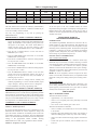
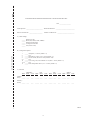
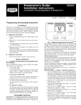
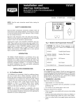
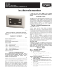
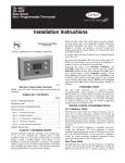
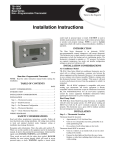
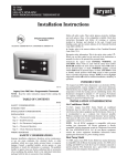
Homeowner’s Guide/
Installation, Start-Up, and Operating Instructions
Standard Programmable Thermostat
Visit www.carrier.com
NOTE: Read the entire instruction manual before starting the installation.
This symbol → indicates a change since the last issue.
<
<
SAFETY CONSIDERATIONS
Improper installation, adjustment, alteration, service, maintenance,
or use can cause fire, electrical shock, or other conditions which
may cause personal injury or property damage. Consult a qualified
installer, for information or assistance. The qualified installer must
use factory-authorized kits or accessories when modifying this
product. Refer to the individual instructions packaged with the kits
or accessories when installing.
Follow all safety codes and wear safety glasses. Read these
instructions thoroughly and follow all warnings or cautions attached to the unit. Consult local and state building codes and Sheet
Metal and Air Conditioning National Association (SMACNA) for
special installation requirements.
Recognize safety information. This is the safety-alert symbol
.
When you see this symbol on the unit or in instructions and
manuals, be alert to the potential for personal injury.
Understand the signal words DANGER, WARNING, and CAUTION. These words are used with the safety-alert symbol. DANGER identifies the most serious hazards which will result in severe
personal injury or death. WARNING signifies hazards which
could result in personal injury or death. CAUTION is used to
identify unsafe practices which would result in minor personal
injury or product and property damage.
HOMEOWNER’S GUIDE
Step 1—Programming and Operating Instructions
AT POWER UP
When power is first applied, AC or HP will appear for 5 seconds
to tell you it is an air conditioner (AC) or a heat pump (HP) model.
After this, the time display will flash to tell you the power has been
off. The day and time will show, within 10 minutes, when the
power went off. Pressing any button will stop the flashing.
SETTING THE CURRENT TIME:
A99068
Fig. 1—Standard Programmable Thermostat
1. To Select the Mode:
Use the MODE button to move between the choices. OFF,
HEAT, COOL, or EMHT will appear on the display. EMHT
will only appear on heat pump models.
2. To Select the Fan Operation:
Use the FAN button to move between continuous fan (indicated by the FAN ON icon) and auto fan operation.
3. To Read the Room Temperature:
The large display reads room temperature until a button is
pressed.
4. To Adjust the Set Point:
The first press of the UP or DOWN button does not change the
set point. It displays the current set point for a period of 5
seconds. Successive presses within this 5 seconds will adjust
the set point and restart the 5 seconds. During the 5 seconds,
the SET TEMP icon will be flashing.
1. Press the TIME/TEMP button. SET TIME flashes on the
display.
PROGRAMMED OPERATION
2. Press the Up or Down button until the correct time is
displayed.
The Standard Programmable Thermostat provides four periods per
day (MORNING, DAY, EVE, NIGHT) and two schedules per
week (MoTuWeThFr and SaSu). A separate time, heat set point,
and cool set point can be set for each period and schedule. Before
starting to actually program the thermostat, fill out Table 1 with the
values you wish to program. (The Energy Star, US Department of
Energy recommended time and temperature values are already
programmed for you as a starting point and are shown on the left
side of the table.)
3. To quickly advance to the proper time, press and hold the UP
or DOWN button.
4. When the correct time appears on the display, press the
HOLD/END button.
NOTE: If you choose not to press the HOLD/END button, the
thermostat will automatically exit the time setting mode after 10
sec.
SETTING THE CURRENT DAY:
1. Press the DAY button to advance to the correct day.
Introduction
The first press of the PROGRAM button brings up the programming mode and places you at the current day and period.
Successive presses move you between the four daily periods.
MANUAL OPERATION
WHILE PROGRAMMING:
TO OPERATE MANUALLY (WITHOUT THE PROGRAMMED COMFORT SCHEDULE):
The TIME/TEMP button moves between selections of SET TIME,
SET TEMP and HEAT, and SET TEMP and COOL. These three
numbers are to be programmed for each of the periods MORNING, DAY, EVE, and NIGHT.
Press the HOLD/END button to make the HOLD icon appear.
Then follow the four steps below:
Manufacturer reserves the right to discontinue, or change at any time, specifications or designs without notice and without incurring obligations.
Book 1 4
PC 101
Catalog No. O3TS-TA32
Printed in U.S.A.
Form TSTAT-26SI
Pg 1
9/01
Replaces: TSTAT-24SI
Tab misc misc
Table 1—Programming Table
ENERGYSTAR FACTORY DEFAULTS
PERIOD
TIME
COOL
HEAT
MORNING
DAY
EVE
6:00 A.M.
8:00 A.M.
5:00 P.M.
78
85
78
68
60
68
MoTuWeThFr
TIME
1)
4)
7)
NIGHT
10:00 P.M.
82
60
10)
NEW COMFORT SCHEDULE
SaSu
COOL
HEAT
TIME
2)
3)
13)
5)
6)
16)
8)
9)
19)
COOL
HEAT
14)
17)
20)
11)
23)
15)
18)
21)
24)
12)
22)
At the first press of the UP or DOWN button, the current
temperature setting will appear on the display. Pressing the UP or
DOWN button again will temporarily change the set point as
needed. At the next programmed time, the programmed comfort
schedule will resume.
The DAY button moves between the weekdays, (MoTuWeThFr)
and the weekend (SaSu) selections. A different schedule may be
set for the weekdays and the weekend.
You may exit programming at any time by pressing the
HOLD/END button.
INSTALLATION, START-UP,
AND OPERATING INSTRUCTIONS
INTRODUCTION
PROGRAMMING A WEEKLY COMFORT SCHEDULE:
1. Press the PROGRAM button. The word PROGRAMMING
appears on the display and the words SET TIME flash on the
display. MoTuWeThFr or SaSu and the present period icons
will appear on the display. The current mode (HEAT or
COOL) will also show. Use the DAY button to select
weekdays and the PROGRAM button to select MORNING.
The Standard Programmable Thermostat is an electronic 24-vac,
manual changeover wall mount thermostat. This thermostat uses
two set points to maintain and control room temperature in both
the heating and air conditioning modes. The thermostat is designed
to maintain +/- 2 degrees (F) accuracy. No batteries are required;
program schedule, temperature, fan, mode, and installer configuration settings are preserved with power off.
2. Press the UP or DOWN button to set the start time for
MORNING (box 1 value).
3. Press the TIME/TEMP button until COOL is on and SET
TEMP flashes on the display.
INSTALLATION CONSIDERATIONS
AIR CONDITIONER MODEL
4. Press the UP or DOWN button to select the cooling temperature set point (box 2 value).
→ The
Standard Programmable AC (air conditioner model only)
thermostat may be wired with or without connecting a common
wire between the indoor equipment and the thermostat. However,
it is recommended to use a common wire whenever possible.
Without a common wire this thermostat becomes ″power stealing.″
This means it will need to steal a small amount of power from the
equipment to which it is connected.
5. Press the TIME/TEMP button until HEAT is on and SET
TEMP flashes on the display.
6. Press the UP or DOWN buttons to select the heating temperature set point (box 3 value).
7. Press the PROGRAM button to advance to the next time
period. Enter time and temperature settings from boxes 4
through 12 for the periods DAY, EVE, and NIGHT by
following steps 2-6 above.
NOTE: All Carrier equipment, with the exception of the Thermostat Conversion Kit, TSTATXXCNV10, is compatible with this
thermostat in both power stealing and non-power stealing connections.
8. Press the DAY button to change between weekday and
weekend programming. To set the weekend schedule, repeat
steps 2 through 7, entering values in boxes 13 though 24.
HEAT PUMP MODEL
The Standard Programmable HP (heat pump) thermostat is not
power stealing and MUST have both R and C wires connected to
operate properly. This thermostat uses a green LED to indicate
auxiliary heat and emergency heat operation.
9. Press END/HOLD to exit the programming mode.
MODIFYING YOUR WEEKLY COMFORT SCHEDULE
If you choose to change any of your weekly schedule, press
PROGRAM at any time. You will enter the programming schedule
at the present day, present mode, but always in the morning period.
You are ready to set the new starting time for the morning period.
One press of the TIME/TEMP button and you are ready to set the
new temperature. Press HOLD/END and you are finished.
INSTALLATION
Step 1—Thermostat Location
Thermostat should be mounted:
•
•
OVERRIDING YOUR COMFORT SCHEDULE
Approximately 5 ft (1.5m) from floor.
Close to or in a frequently used room, preferably on an inside
partitioning wall.
On a section of wall without pipes or duct work.
There are two ways to override your comfort schedule:
•
Method 1—Manual Operation
Thermostat should NOT be mounted:
By pressing the HOLD/END button to turn on the HOLD icon, the
thermostat will maintain the current temperature settings and
ignore the comfort schedule for an indefinite period of time. The
word HOLD will appear in the display. Press the HOLD/END
button a second time and the thermostat will return the temperature
settings to the programmed comfort schedule. Pressing
HOLD/END will not alter your programmed comfort schedule.
•
Close to a window, on an outside wall, or next to a door leading
to the outside.
•
Exposed to direct light and heat from a lamp, sun, fireplace, or
other heat-radiating object which may cause a false reading.
•
Close to or in direct airflow from supply registers and return-air
grilles.
•
In areas with poor air circulation, such as behind a door or in
an alcove.
Method 2—Temporary Override
2
Step 2—Install Thermostat
OPTION 1—ANTICIPATOR VALUE ADJUSTMENT
This adjustment controls the sensitivity and cycle rate of the
thermostat. Higher numbers decrease the cycle rate. Lower numbers increase the cycle rate. However, this feature will not allow
more than 4 equipment cycles per hour (or 1 cycle every 15
minutes), regardless of setting. Values can range from 1 to 3.
Factory default setting is 2. This default selection will provide
optimum performance in nearly all installations. Try this setting
first. Do not change setting unless there is evidence or need to do
so. Unlike conventional anticipators, this setting is not to be
determined by current draw. There is no need to measure, know, or
compensate for current.
Before installing thermostat, turn off all power to unit. There
may be more than 1 disconnect. Electrical shock can cause
personal injury or death.
1. Turn OFF all power to unit.
2. If an existing thermostat is being replaced:
a. Remove existing thermostat from wall.
b. Disconnect wires from existing thermostat, one at a time.
Be careful not to allow wires to fall back into wall.
TO SELECT:
c. As each wire is disconnected, record wire color and
terminal marking.
1. Enter configuration mode if not already there (see above).
2. Use UP and DOWN buttons to make the large (now flashing)
display indicate 1.
d. Discard or recycle old thermostat.
NOTE: Mercury is a hazardous waste and MUST be disposed of
properly.
3. Press the TIME/TEMP button once to flash the small display.
4. Use UP and DOWN buttons to move between 1, 2, or 3 on the
small display. Factory default is 2.
3. Separate front and back plastic assembly of thermostat.
4. Route thermostat wires through hole in mounting base. Level
mounting base against wall (for aesthetic value only, thermostat need not be leveled for proper operation) and mark wall
through 2 mounting holes.
5. Press TIME/TEMP button again to flash the large display for
selection of another option, or press HOLD/END TO exit the
configuration mode.
5. Drill two 3/16-in. mounting holes in wall where marked.
OPTION 3—FAHRENHEIT/CELSIUS SELECTION
6. Secure back plate to wall with 2 anchors and screws provided
making sure all wires extend through hole in plastic.
This selection operates the thermostat in either Fahrenheit or
Celsius.
7. Connect wires to proper terminal location on backplate.
TO SELECT:
1. Enter configuration mode if not already there (see above).
8. Push any excess wire back into wall. Seal hole in wall to
prevent air leaks. Leaks can affect thermostat operation. Any
excess wire left inside thermostat casing may also affect
thermostat operation by interfering with airflow across the
temperature sensor.
2. Use UP and DOWN buttons to make the large (now flashing)
display indicate 3.
3. Press TIME/TEMP button once to flash the small display.
4. Use UP and DOWN buttons to move between F or C on the
small display. Factory default is F.
9. Snap thermostat together making sure assembly is secure.
→ 10.
Turn ON power to unit.
5. Press TIME/TEMP button again to flash the large display for
selection of another option, or press HOLD/END to exit the
configuration mode.
On power up, depending on the thermostat model being used, the
LCD readout will display either, AC for air conditioner model
(1-stage heat/1-stage cool), or HP for heat pump model (2-stage
heat/1-stage cool).
OPTION 4—G (FAN) ON WITH W (HEAT) SELECTION
This selection determines whether G (fan) output is to be ON or
OFF when W (furnace or strip heat) output is ON. Most furnaces
and fan coils manage their own blowers and do not require a
separate G signal. For these applications, select OFF. Some
auxiliary heaters require a separate G signal from the thermostat to
turn on the blower. In this case, select ON.
Step 3—Set Thermostat Configuration
Available thermostat configuration options and their numbers are:
Option 1 -- Anticipator adjustment
Option 2 -- Not available
Option 3 -- Fahrenheit or Celsius operation
TO SELECT:
Option 4 -- Enable fan (G) ON with heat (W)
1. Enter configuration mode if not already there (see above).
Options 5 through 9 -- Not available
2. Use UP and DOWN buttons to make the large (now flashing)
display indicate 4.
Option 10 -- O (reversing valve) On with Heat or Cool (present on
Heat Pump model only)
3. Press TIME/TEMP button once to flash the small display.
Options 11 and 12 -- Not available
4. Use UP and DOWN buttons to move between ON or OF (off)
on the small display. Factory default is OF (off).
Option 13 -- Room temperature offset adjustment
An explanation for each configuration option is as follows.
5. Press TIME/TEMP button again to flash the large display for
selection of another option, or press HOLD/END to exit the
configuration mode.
TO ENTER THE CONFIGURATION MODE:
Press and hold FAN button for approximately 10 sec until room
temperature disappears and the display reads ″1″ and is flashing.
You are now in configuration mode.
NOTE: If HOLD/END button is pressed, or if no button is
pressed for 3 minutes, the thermostat will exit configuration mode
and return to normal operation. To re-enter configuration mode,
the FAN button must be pressed and held for 10 sec again.
OPTION 10—O (REVERSING VALVE) ON WITH HEAT
OR COOL SELECTION
This selection is only available on heat pump model thermostats.
This selection determines whether the reversing valve is energized
in the heating or cooling mode.
While in configuration mode, the following options are available:
3
TO SELECT:
starts counting down when the output is turned on, (e.g., if Y
output is turned on for 9 minutes and then satisfies, it cannot turn
back on for another 6 minutes regardless of demand). However,
pressing UP and FAN buttons simultaneously or changing the set
point will override the timer for 1 cycle.
1. Enter configuration mode if not already there (see above).
2. Use UP and DOWN buttons to make the large (now flashing)
display indicate 10.
3. Press TIME/TEMP button once to flash the small display.
MINIMUM ON TIMER
4. Use UP and DOWN buttons to move between H (energized in
heating) or C (energized in cooling) on the small display.
Factory default is C.
Once the equipment has turned on, it will remain on for a
minimum of 3 minutes regardless of demand. However, the
equipment can turn off in less than 3 minutes if a change in set
point, or a change in mode occurs.
5. Press TIME/TEMP button again to flash the large display for
selection of another option, or press HOLD/END to exit the
configuration mode.
STAGING TIMER
OPTION 13—ROOM TEMPERATURE OFFSET ADJUSTMENT
If the thermostat is a heat pump model, it has 2-stage heat
capability. In normal operation there is a 15-minute delay between
the first and second stages of heat. The Y output will energize first,
then 15 minutes later, W is allowed to come on if the thermostat
determines it is not satisfying the demand.
This option allows calibration (or deliberate miscalibration) of the
room temperature sensor. There are various reasons why homeowners may want to have displayed temperature adjusted to a
higher or lower value.
However, if the heating demand is greater than 5°, there will be
only a 3-minute delay before bringing on W.
NOTE: Do not adjust for 30 minutes after installation because
board may be heated by handling.
ERROR MESSAGES
The selected number is the number of degrees, plus or minus,
which will be added to actual temperature. The numbers can range
between -5 and +5.
E4 will be displayed if the thermostat has an internal memory
failure. If E4 appears, replace thermostat. -- (two dashes) will be
displayed if the thermostat cannot properly read room temperature.
If -- appears, replace thermostat.
TO SELECT:
1. Enter configuration mode if not already there (see above).
2. Use UP and DOWN buttons to make the large (now flashing)
display indicate 13.
Step 5—Check Thermostat Operation
3. Press the TIME/TEMP button once to flash the small display.
FAN OPERATION
4. Use UP and DOWN buttons to move between -5 and 5 in 1
degree steps on the small display. Factory default is 0.
1. Press FAN button. This will start continuous fan operation.
FAN ON icon will turn on.
5. Press TIME/TEMP button again to flash the large display for
selection of another option, or press HOLD/END to exit the
configuration mode.
2. Press FAN button again. This will stop continuous fan
operation. FAN ON icon will turn off.
HEATING OPERATION
Step 4—Thermostat Operation
1. Press MODE button until HEAT is displayed.
TEMPERATURE DISPLAY
2. Press UP button until LCD readout reads 3° above room
temperature. Press UP and FAN buttons simultaneously to
defeat timers. Heating system should begin to operate immediately.
Thermostat will display room temperature until UP or DOWN
button is pressed. The words SET TEMP appear when these
buttons are pressed and the current set point is displayed. If no
buttons are pressed for 5 sec, the display will change back to show
room temperature.
3. For HP thermostats only, press MODE button until EMHT
(emergency heat) appears. Press UP and FAN buttons simultaneously to defeat timers. Emergency heating (W is ON, Y is
OFF) should begin immediately.
TIMEGUARD TIMER
A 5-minute timeguard is built into the thermostat immediately
upon power up, and any time the compressor turns off. The
compressor will not turn on until the timeguard has expired. The
timeguard affects only compressor operation. Pressing UP and
FAN buttons simultaneously will override the timeguard for 1
cycle.
COOLING OPERATION
1. Press MODE button until COOL is displayed.
2. Press DOWN button until LCD readout reads 3° below room
temperature. Press UP and FAN buttons simultaneously to
defeat timers. Cooling system should begin to operate immediately.
CYCLE TIMER
In normal heating and cooling operation the thermostat will not
allow more than 4 equipment cycles per hour (or 1 cycle every 15
minutes). Both the Y and W outputs have a 15-minute timer that
4
TYPICAL
FAN COIL/ SINGLE-SPEED
FURNACE AIR CONDITIONER
AC
THERMOSTAT
TYPICAL
FAN COIL/
FURNACE
AC
THERMOSTAT
HEATING
W
W
HEATING
W
W
FAN
G
G
FAN
G
G
24 VAC HOT
R
R
24 VAC HOT
R
R
24 VAC COMM
C
COOLING
Y
N/A
O
*
C
C
24 VAC COMM
C
Y
Y
COOLING
Y
N/A
O
* See note 1
C
Y
* See note 1
Fig. 2—Typical Air Conditioner
A01399
Fig. 3—Typical Heat Only
AC
THERMOSTAT
HEAT PUMP
THERMOSTAT
*
TYPICAL SINGLE-SPEED
HEAT PUMP
FAN COIL
A01400
TWO-ZONE
THERMOSTAT
INPUT
HEATING
W
W1
FAN
G
G
24 VAC HOT
R
R
24 VAC COMM
C
C
COOLING
Y
Y1
N/A
O
HEAT STAGE 2
W
W
W
REVERSING
VALVE
O
O
O
FAN
G
G
24 VAC HOT
R
R
R
24 VAC COMM
C
C
C
Fig. 5—Two Zone with Air Conditioner
HEAT/COOL
STAGE 1
Y
Y
Y
NOTE: 1. It is recommended to use a 5-wire hookup whenever
possible. However, if “power stealing” connection is used, leave off C
connection between thermostat and equipment.
A98217
Fig. 4—Typical Heat Pump
NOTE: Two Zone applications must use 5-wire hookup.
5
A01401
✂
STANDARD PROGRAMMABLE THERMOSTAT CONFIGURATION RECORD
Date __________________
Owner/Operator __________________________ Thermostat Model No. ______________________________
Indoor Unit Model No. _____________________
Outdoor Unit Model No. ___________________________
A) Mode Settings
______
______
______
______
______
Hold (On or Off)
Mode (OFF, HEAT, COOL, EMHT)
Heating Set Point Value
Cooling Set Point Value
Fan (AUTO or ON)
Cut and Save for Customer File
B) Configuration Options
1
_____
2
_____
3
_____
4
_____
5-9 _____
10
_____
11-12 _____
13
_____
Anticipator (1-3: factory default = 2)
N/A
Fahrenheit or Celsius (F or C: factory default = F)
Fan On with W (Off or On: factory default = Off)
N/A
O (reversing valve) On with Heat or Cool (H or C: factory default = C)
N/A
Room Temperature Offset (-5 to + 5: factory default = 0)
C) Schedule
TIME
MORNING
HEAT COOL TIME
DAY
HEAT
COOL TIME
EVE
HEAT
COOL TIME
NIGHT
HEAT COOL
Monday Friday ______ ____
____
______ ____
____
______ ____
____
______ ____
____
Saturday Sunday ______ ____
____
______ ____
____
______ ____
____
______ ____
____
A99272
6
7
Copyright 2001 CARRIER Corp. • 7310 W. Morris St. • Indianapolis, IN 46231
tstat-26si
Manufacturer reserves the right to discontinue, or change at any time, specifications or designs without notice and without incurring obligations.
Book 1 4
Tab misc miscPC 101
Catalog No. O3TS-TA32
Printed in U.S.A.
Form TSTAT-26SI
Pg 8
9/01
Replaces: TSTAT-24SI