1
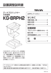
MULTIMEDIA PROJECTOR
LV-CL15 Ceiling-mounting Hanger
ENG
Installation Manual
MULTIMEDIA-PROJEKTOR
LV-CL15 Deckenbefestigung
GER
Installationshandbuch
キヤノン パワープロジェクター
天吊り金具 LV-CL15
使用説明書
JPN
MULTIMEDIA PROJECTOR
LV-CL15 Ceiling-mounting Hanger
Installation Manual
Thank you for your purchase of the Canon Multimedia Projector Ceiling-mounting
Hanger.
Please read this installation manual carefully to ensure proper use.
• This ceiling-mounting hanger is for use with the LV-7385/LV-7380/LV-7285/LV-7280/
LV-8310/LV-8215/LV-7375/LV-7370/LV-7275/LV-8300.
(March 2010)
Special skills are required for the installation of the projector.
This work should never be performed by the customer.
Consult your dealer for installing the projector on the ceiling.
To the Dealer and the Installer
For the safety of the customer, we ask that the installation work be started after careful
attention is paid to the strength of the mounting location to be sure it will withstand the
weight of the projector and ceiling-mounting hanger.
CONTENTS
Heed the Following.............................................................................................ENG-2
Preparation..........................................................................................................ENG-4
■List of Packaged Parts................................................................................................ENG-4
■Required Tools............................................................................................................ENG-4
■Names of the Parts.....................................................................................................ENG-5
■Dimensions..................................................................................................................ENG-5
Guide to Screen Size and Projector Mounting Position....................................ENG-6
■Screen Size and Projection Distance .........................................................................ENG-6
< LV-7385/LV-7380/LV-7285/LV-7280/LV-7375/LV-7370/LV-7275 >............................ENG-6
< LV-8310/LV-8215 >...................................................................................................ENG-7
< LV-8300 >.................................................................................................................ENG-8
■Screen Size Conversion Table ...................................................................................ENG-9
< LV-7385/LV-7380/LV-7285/LV-7280/LV-7375/LV-7370/LV-7275 >............................ENG-9
< LV-8310/LV-8215/LV-8300 >.....................................................................................ENG-9
Mounting the Projector.....................................................................................ENG-10
Adjustment of the Projection Angle..................................................................ENG-14
■Distortion Adjustment...............................................................................................ENG-14
■Fine Adjustment........................................................................................................ENG-16
Specifications....................................................................................................ENG-16
Heed the Following
This symbol alerts the user that important information concerning the
operation and maintenance of this ceiling-mounting hanger has been
provided. The information should be read carefully to avoid problems.
WARNING
• When installing the projector, be sure to
do so as explained in this manual. The
projector may fall and cause injury if it is
installed improperly.
• To prevent the projector from falling, install
it in a place and fasten it in a way with
sufficient strength to support the combined weight (4.6 kg) of the projector (3.3
kg) and the ceiling-mounting hanger (1.3
kg) for an extended period of time as well
as to withstand earthquakes. Insufficient
strength or fastening may result in the
projector falling and causing injury.
• To ensure safety, be sure to tighten the
bolts and screws securely. Also be sure
to use the included units and other metal
fittings. Failure to do so may result in the
projector falling and causing injury.
• When sliding the opening of the mounting adapter over the pin of the ceilingmounting hanger, check that the pin of the
ceiling-mounting hanger is fully seated in
the opening. If not, the projector may fall
and cause injury.
• Be sure to use the supplied wires to install
the projector. Failure to do so may result
in the projector falling and causing injury.
• Do not modify any parts. Doing so may
result in the projector falling and causing
injury.
• Do not use broken parts. Doing so may
result in the projector falling and causing
injury. If a part should be broken, consult
your dealer.
• Do not look into the lens when the projector is turned on. Doing so could damage
your eyesight.
• Make adjustments as described in this
manual.
Incorrect adjustments may result in the
projector falling and causing injury.
ENG-2
Heed the Following
CAUTION
Installation Precautions
• Do not obstruct the projector’s ventilation holes. Doing so will prevent the dissipation of heat and may result in fires. In
particular, do not use the projector in the
following ways:
Do not install the projector in a wall or in a
tight place where ventilation is poor, place
a cover it, etc.
• Do not install the projector in front of the
outlets of an air conditioner or heater or in
a place where vibrations are strong.
Doing so may result in fires.
• Do not install the projector in humid or
dusty places or exposed to smoke or
steam (such as near cooking equipment
or humidifiers). Doing so may result in
fires.
• When installing the projector, leave sufficient space between it and surrounding
objects. Failure to leave sufficient space
will prevent the dissipation of heat and
may result in fires.
• When cabling, do not obstruct the projector’s ventilation holes with cables. Doing
so will prevent the dissipation of heat and
may result in failure of the projector.
• When removing the screws on left and
right on the mounting adapter, be sure
to support the projector while doing so.
Failing to do so may result in the projector swinging back abruptly and causing
injury.
• for PLUGGABLE EQUIPMENT, the socket-outlet shall be installed near the equipment and shall be easily accessible.
• Special techniques are required for the
installation work of the projector and
installation work should only be undertaken by qualified and licensed installers.
• Canon will not accept any responsibility related to any accidents or incidents
due to insufficient or inferior mounting
techniques.
Installation Location
Avoid places of high temperature or low
temperature.
Ambient operating temperature : 5°C to
40°C. (Quiet mode selected automatically
at 35°C to 40°C)
Avoid places exposed to direct sunlight and
the vicinity of ventilation holes of room air
conditioning and heating.
Avoid rooms with a lot of dust, humidity,
greasy smoke, or tobacco smoke.
Dirt will adhere to optical parts such as
lenses and mirrors and this will cause a
deterioration of image quality.
Avoid places in which the screen is exposed
to direct sunlight or illumination light.
When surrounding light directly hits the
screen, the image appears washed out and
is difficult to view.
ENG-3
Preparation
■List of Packaged Parts
• Fixed ceiling part …1
• Up-down angle adjustment screws (M5)
…4
• Projector mounting adapter …1
• Projector mounting screws (M4) …3
• Installation manual (this document) …1
• Anti-fall wires …2
■Required Tools
• Phillips screwdriver
ENG-4
Preparation
■Names of the Parts
Inclination axis screws*
Left-right angle adjustment screws*
Fixed ceiling part
Projector mounting
adapter
Front
side
Right
side
Inclination adjustment screws*
Up-down angle adjustment screws*
* There are also screws on the opposite side.
■Dimensions (Unit: mm)
Fixed Ceiling Part Bolt Hole Position
Dimensions
Fixed Ceiling Part and Lens Center
Dimensions Diagram
210
180
47.7
134
Center line of
fixed ceiling part
4-∅10
79.5
113.9
Distance to lens end
Lens center
Lens center
Center line of fixed ceiling part
ENG-5
Guide to Screen Size and Projector Mounting Position
■Screen Size and Projection Distance
< LV-7385/LV-7380/LV-7285/LV-7280/LV-7375/LV-7370/LV-7275 >
Use this guide when considering the distance to the screen and the screen size.
• The ceiling mount unit can be adjusted up and down a maximum of +/−10°, but if too much
of an angle is taken the image will show some distortion. Therefore, it is recommended that an
adjustment is made in conjunction with the screen projection angle.
• Recommended screen sizes for projectors are from 21 inches to 300 inches. (Screen sizes
represent the diagonal dimension.)
Optional axis when image is projected at
right angle to the screen.
113.9 mm (*1)
134 mm
H2
32"
67"
40"
(*2)
Screen
(*4)
(*3)
126"
80"
1.2 m
H1
165"
150"
2.5 m
250"
200"
4.7 m
300"
6.2 m
Zoom (min.)
300" Zoom (max.)
9.4 m (Zoom max.)
11.3 m (Zoom min.)
(*1) Distance from center of fixed ceiling part to end of main unit lens.
(*2) Distance of lens center from ceiling mount surface of fixed ceiling part.
(*3) The angle is 7.8 to 7.9° using a telephoto setting for distances from lens center (horizontal) to screen center.
(*4) The angle is 9.3 to 9.5° using a wide angle setting for distances from lens center (horizontal) to screen center.
Throw Distance and Screen Size
Screen size
(W×H) cm
Projection
distance
Zoom (max)
Projection
distance
Zoom (min)
H1
H2
21"
25"
30"
40"
43×32
51×38
61×46
81×61
122×91 163×122 203×152 305×229 366×274 406×305 508×381 610×457
60"
80"
100"
150"
180"
−
0.8 m
(2.6')
0.9 m
(3.0')
1.2 m
(3.9')
1.9 m
(6.2')
2.5 m
(8.2')
3.1 m
(10.2')
4.7 m
(15.4')
5.6 m
(18.4')
6.2 m
(20.3')
7.8 m
(25.6')
9.4 m
(30.8')
0.8 m
(2.6')
0.9 m
(3.0')
1.1 m
(3.6')
1.5 m
(4.9')
2.2 m
(7.2')
3.0 m
(9.8')
3.7 m
(12.1')
5.6 m
(18.4')
6.8 m
(22.3')
7.5 m
(24.6')
9.4 m
(30.8')
11.3 m
(37.1')
27 cm
(0.9')
5 cm
(0.2')
32 cm
(1.1')
6 cm
(0.2')
39 cm
(1.3')
7 cm
(0.2')
51 cm
(1.7')
10 cm
(0.3')
77 cm 103 cm 129 cm 193 cm 231 cm 257 cm 321 cm 386 cm
(2.5')
(3.4')
(4.2')
(6.3')
(7.6')
(8.4') (10.5') (12.7')
14 cm 19 cm 24 cm 36 cm 43 cm 48 cm 60 cm 71 cm
(0.5')
(0.6')
(0.8')
(1.2')
(1.4')
(1.6')
(2.0')
(2.3')
200"
250"
300"
H1 and H2: H1 is the height of the screen from the intersection of optical axis and screen surface, and H2 is the height
of the intersection when an image is projected at right angle to the screen.
Using the Diagrams
Referring to the diagram, screen sizes that can be used at a projection distance of 3 m will range from 80
inches to 95 inches.
To project to a screen size of 180 inches, the projection distance will range from 5.6 to 6.8 m according to
the diagram.
See Page ENG-9 for the vertical and horizontal dimensions of the screen size.
ENG-6
Guide to Screen Size and Projector Mounting Position
< LV-8310/LV-8215 >
Use this guide when considering the distance to the screen and the screen size.
• The ceiling mount unit can be adjusted up and down a maximum of +/−10°, but if too much
of an angle is taken the image will show some distortion. Therefore, it is recommended that an
adjustment is made in conjunction with the screen projection angle.
• Recommended screen sizes for projectors are from 21 inches to 300 inches. (Screen sizes
represent the diagonal dimension.)
Optional axis when image is projected at
right angle to the screen.
113.9 mm (*1)
134 mm
H2
33"
40"
(*2)
65"
(*4)
Screen
125"
80"
(*3)
H1
165"
1.3 m
150"
248"
2.6 m
300"
5.0 m
200"
Zoom (min.)
6.6 m
300"
Zoom (max.)
9.9 m (Zoom max.)
12.0 m (Zoom min.)
(*1) Distance from center of fixed ceiling part to end of main unit lens.
(*2) Distance of lens center from ceiling mount surface of fixed ceiling part.
(*3) The angle is 7.9 to 8.3° using a telephoto setting for distances from lens center (horizontal) to screen center.
(*4) The angle is 9.5 to 9.9° using a wide angle setting for distances from lens center (horizontal) to screen center.
Throw Distance and Screen Size
Screen size
(W×H) cm
Projection
distance
Zoom (max)
Projection
distance
Zoom (min)
H1
H2
21"
25"
30"
40"
45×28
54×34
65×40
86×54
129×81 172×108 215×135 323×202 388×242 431×269 538×337 646×404
60"
80"
100"
150"
180"
–
0.8 m
(2.6')
1.0 m
(3.2')
1.3 m
(4.2')
2.0 m
(6.4')
2.6 m
(8.6')
3.3 m
(10.8')
5.0 m
(16.3')
6.0 m
(19.5')
6.6 m
(21.7')
8.3 m
(27.2')
0.8 m
(2.6')
1.0 m
(3.2')
1.2 m
(3.8')
1.6 m
(5.1')
2.4 m
(7.7')
3.2 m
(10.4')
4.0 m
(13.0')
6.0 m
(19.5')
7.2 m
(23.5')
8.0 m
(26.1')
10.0 m 12.0 m
(32.7') (39.2')
26 cm
(0.8')
2 cm
(0.1')
31 cm
(1.0')
3 cm
(0.1')
37 cm
(1.2')
4 cm
(0.1')
49 cm
(1.6')
5 cm
(0.2')
74 cm
(2.4')
7 cm
(0.2')
98 cm 123 cm 184 cm 221 cm 246 cm 307 cm 369 cm
(3.2')
(4.0')
(6.0')
(7.3')
(8.1') (10.1') (12.1')
9 cm 12 cm 18 cm 21 cm 24 cm 29 cm 35 cm
(0.3')
(0.4')
(0.6')
(0.7')
(0.8')
(1.0')
(1.2')
200"
250"
300"
9.9 m
(32.6')
H1 and H2: H1 is the height of the screen from the intersection of optical axis and screen surface, and H2 is the height
of the intersection when an image is projected at right angle to the screen.
Using the Diagrams
Referring to the diagram, screen sizes that can be used at a projection distance of 3 m will range from 80
inches to 90 inches.
To project to a screen size of 180 inches, the projection distance will range from 6.0 to 7.2 m according to
the diagram.
See Page ENG-9 for the vertical and horizontal dimensions of the screen size.
ENG-7
Guide to Screen Size and Projector Mounting Position
< LV-8300 >
Use this guide when considering the distance to the screen and the screen size.
• The ceiling mount unit can be adjusted up and down a maximum of +/−10°, but if too much
of an angle is taken the image will show some distortion. Therefore, it is recommended that an
adjustment is made in conjunction with the screen projection angle.
• Recommended screen sizes for projectors are from 21 inches to 300 inches. (Screen sizes
represent the diagonal dimension.)
Optional axis when image is projected at
right angle to the screen.
113.9 mm (*1)
134 mm
H2
31"
40"
(*2)
66"
Screen
(*4)
125"
80"
H1
166"
150"
1.1 m
(*3)
2.3 m
247"
200"
300"
4.4 m
Zoom (min.)
300"
5.9 m
Zoom (max.)
8.8 m (Zoom max.)
10.7 m (Zoom min.)
(*1) Distance from center of fixed ceiling part to end of main unit lens.
(*2) Distance of lens center from ceiling mount surface of fixed ceiling part.
(*3) The angle is 7.5 to 8.0° using a telephoto setting for distances from lens center (horizontal) to screen center.
(*4) The angle is 9.1 to 9.6° using a wide angle setting for distances from lens center (horizontal) to screen center.
Throw Distance and Screen Size
Screen size
(W×H) cm
Projection
distance
Zoom (max)
Projection
distance
Zoom (min)
H1
H2
21"
25"
30"
40"
45×28
54×34
65×40
86×54
129×81 172×108 215×135 323×202 388×242 431×269 538×337 646×404
60"
80"
100"
150"
180"
–
0.7 m
(2.3')
0.9 m
(3.0')
1.1 m
(3.6')
1.7 m
(5.6')
2.3 m
(7.5')
2.9 m
(9.5')
4.4 m
(14.4')
5.3 m
(17.4')
5.9 m
(19.4')
7.4 m
(24.3)
8.8 m
(28.9')
0.7 m
(2.3')
0.9 m
(3.0')
1.0 m
(3.3')
1.4 m
(4.6')
2.1 m
(6.9')
2.8 m
(9.2')
3.5 m
(11.5')
5.3 m
(17.4')
6.4 m
(21.0')
7.1 m
(23.3')
8.9 m
(29.2')
10.7 m
(35.1')
24 cm
(0.8')
4 cm
(0.1')
29 cm
(0.9')
5 cm
(0.2')
34 cm
(1.1')
6 cm
(0.2')
46 cm
(1.5')
8 cm
(0.3')
69 cm
(2.3')
12 cm
(0.4')
92 cm 114 cm 172 cm 206 cm 229 cm 286 cm 343 cm
(3.0')
(3.8')
(5.6')
(6.8')
(7.5')
(9.4') (11.3')
16 cm 20 cm 30 cm 36 cm 40 cm 50 cm 61 cm
(0.5')
(0.7')
(1.0')
(1.2')
(1.3')
(1.7')
(2.0')
200"
250"
300"
H1 and H2: H1 is the height of the screen from the intersection of optical axis and screen surface, and H2 is the height
of the intersection when an image is projected at right angle to the screen.
Using the Diagrams
Referring to the diagram, screen sizes that can be used at a projection distance of 3 m will range from 90
inches to 100 inches.
To project to a screen size of 180 inches, the projection distance will range from 5.3 to 6.4 m according to
the diagram.
See Page ENG-9 for the vertical and horizontal dimensions of the screen size.
ENG-8
Guide to Screen Size and Projector Mounting Position
■Screen Size Conversion Table
< LV-7385/LV-7380/LV-7285/LV-7280/LV-7375/LV-7370/LV-7275 >
Using the Table
The dimensions of a 100 inch screen size according to the table will be approximately 2 m horizontally and
approximately 1.5 m vertically.
(Inches)
300
(m)
4.5
270
Height of the screen
4.0
240
3.5
200
3.0
180
2.5
150
120
2.0
100
1.5
80
60
1.0
40
0.5
0
25
0
0.5 1.0 1.5 2.0 2.5 3.0 3.5 4.0 4.5 5.0 5.5 6.0 (m)
Width of the screen
< LV-8310/LV-8215/LV-8300 >
Using the Table
The dimensions of a 100 inch screen size according to the table will be approximately 2.15 m horizontally
and approximately 1.34 m vertically.
(Inches)
300
(m)
4.5
Height of the screen
4.0
270
3.5
240
3.0
200
180
2.5
150
2.0
120
100
1.5
80
1.0
40
0.5
0
60
25
0
0.5 1.0 1.5 2.0 2.5 3.0 3.5 4.0 4.5 5.0 5.5 6.0
Width of the screen
ENG-9
6.5 (m)
Mounting the Projector
1
Attach the Fixed Ceiling Part to
the Ceiling
First, partially tighten the four screws, then
tighten the screws firmly after positioning.
Fixed ceiling
part
WARNING!
Use M8 bolts for the fixed ceiling part.
Use of types other than M8 could cause
the projector to fall.
2
Attach the Projector Mounting Adapter to the Projector
Use three M4 screws to mount the projector mounting adapter.
M4
ENG-10
Mounting the Projector
3
Suspend the Projector from the Fixed Ceiling Part
Slide the slotted part of the projector mounting adapter over the pin of the fixed ceiling part
and push all the way to the back.
The projector is temporarily suspended in this condition and attention must be paid so that
the unit does not fall since it is not fixed in place.
Slotted part of mounting adapter
Pin of fixed ceiling
part
4
Temporarily Fasten the Projector Mounting Adapter
Temporarily fasten by partially tightening the four supplied (M5) screws.
Tighten firmly after completing the screen projection angle adjustment.
Temporarily fasten the
other side too.
ENG-11
Mounting the Projector
5
Attach the wires to the projector and the ceiling suspension
unit.
Be sure to install the two wires as described below to prevent the projector from falling.
• Installing anti-fall wire (The first
wire)
[Projector side]
❶Pass the ring of the larger wire
through the carrying handle of the
projector.
1
[Fixed ceiling part]
❷Put the screw (M5) of the projector
mounting adapter through the ring in
wire to mount.
2
• Installing anti-fall wire (The second
wire)
[Fixed ceiling part]
❶Pass the ring of the larger wire
through the hole of the ceiling suspension unit.
2
1
[Projector side]
❷Turn the rear adjustment foot nearest
the main power switch and remove it
from the projector.
❸Pass the rear adjustment foot’s screw
through the ring in wire, then install
the rear adjustment foot back on the
projector.
3
ENG-12
Mounting the Projector
HINT: Installation Examples
• When the Ceiling is Wood Construction:
Mounting board
(Strong enough to support the weight of the whole unit.)
Bolt (M8)
Washer
Beam
Nut and washer
• When the Ceiling is Concrete Construction:
Anchor nut (Purchase commercially-available M8-type anchor nuts
that are strong enough to endure the weight of the whole unit.)
Ceiling
Nut and washer
Bolt (M8)
NOTE : Mounting boards, M8-type anchor nuts, bolts, nuts and washers are commercially
available.
ENG-13
Adjustment of the Projection Angle
Before the Adjustment
• Refer to the user’s manual of the projector, switch on the power and project an image.
• Refer to the section “Image flip H/V” of Setup and select the projection orientation.
• Select “Ceiling mounted” when projection is from the front side, and “Rear, Ceiling
mounted” when projection is from the rear side.
• Provisionally determine the projection size with the manual zoom, then perform the
angle adjustment.
Adjustment of the projection angle should generally follow the steps described below.
1. Distortion Adjustment
2. Fine Adjustment
Adjust each of the left-right, up-down, and
inclination angles so that the projected image
becomes rectangular.
It is acceptable if the image extends beyond
the screen at this time.
Adjust the lens shift function of Finely adjust
each of the left-right, up-down, and inclination angles of the fittings so that the projected
image coincides with the screen.
■Distortion Adjustment
1
Adjust the Left-Right Angle
Upper
and lower
edges
Turn the projector left and right so that
the upper and lower edges of the screen
are parallel, then firmly tighten the four
left-right angle adjustment screws. It is
acceptable if the image extends beyond
the screen.
10° 10°
Maximum adjustment
angle +/−10°
Left-right angle adjustment screws
(There are also screws on the
opposite side.)
ENG-14
Adjustment of the Projection Angle
2
Adjust the Up-Down Angle
Turn the projector up and down so that the left and right edges of the screen are parallel,
then firmly tighten the four up-down angle adjustment screws. It is acceptable if the image
extends beyond the screen.
Left and right edges
10°
10°
Maximum adjustment
angle +/−10°
3
Up-down angle adjustment screws
(There are also screws on the opposite side.)
Adjust the Inclination
Adjust so that the image is projected to the screen without being slanted, then firmly tighten
the four inclination adjustment screws. Lastly, tighten the two inclination axis screws if they
are loose.
Inclination axis screw
10°
10°
Inclination adjustment screws
(There are also screws on the opposite side.)
Maximum adjustment
angle +/−10°
If the adjustment does not work out, readjust from Step
ENG-15
1.
Adjustment of the Projection Angle
■Fine Adjustment
Loosen the same screws that were used in the distortion adjustment and finely
adjust the angle so that the projected image fits the screen, then tighten all the
screws (i.e., a total of 14 including the inclination axis screws).
After the adjustments, check that the ceiling-mounting hanger
and the projector are fixed securely.
Specifications
Product Name:
Model:
Adjustment angle:
Dimensions:
Weight:
Supplied Items:
Ceiling-mounting hanger
LV-CL15
Up-down angle +/−10°
Left-right angle +/−10°
Inclination angle +/−10°
327 (W) × 166 (D) × 88 (H) mm
(when assembled, not including protruding parts)
Approximately 1.3 kg
Fixed ceiling part............................................... 1
Projector mounting adapter............................... 1
Projector mounting screws (M4)........................ 3
Up-down angle adjustment screws (M5)............ 4
Anti-fall wires..................................................... 2
Installation manual............................................. 1
Specifications and appearance are subject to change without notice.
ENG-16
MULTIMEDIA-PROJEKTOR
LV-CL15 Deckenbefestigung
Installationshandbuch
Vielen Dank für den Erwerb der Canon Multimedia Projektor Deckenbefestigung.
Bitte lesen Sie das Installationshandbuch sorgfältig um eine sachgerechte Nutzung zu gewährleisten.
• Diese Deckenbefestigung ist für die Modelle LV-7385/LV-7380/LV-7285/LV-7280/LV-8310/
LV-8215/LV-7375/LV-7370/LV-7275/LV-8300 geeignet.
(März 2010)
Für die Montage des Projektors sind Fachkenntnisse erforderlich.
Diese Arbeit sollte auf keinen Fall vom Kunden ausgeführt werden.
Für die Installierung des Projektors an die Decke, wenden Sie sich an Ihren Verkäufer.
An den Verkäufer und den Monteur
Um die Sicherheit des Kunden zu gewährleisten, sollte sichergestellt sein, dass die
Anbringung erst beginnt, wenn der Ort der Befestigung daraufhin überprüft ist, ob er dem
Gewicht des Projektors und der Deckenbefestigung standhält.
INHALT
Beachten Sie Folgendes.....................................................................................GER-2
Vorbereitung........................................................................................................GER-4
■Auflistung der mitgelieferten Teile...............................................................................GER-4
■Erforderliche Werkzeuge.............................................................................................GER-4
■Bezeichnung der Teile.................................................................................................GER-5
■Abmessungen.............................................................................................................GER-5
Anleitung zur Bildschirmgröße und Aufstellungsposition des Projektors........GER-6
■Bildschirmgröße und Projektionsabstand...................................................................GER-6
< LV-7385/LV-7380/LV-7285/LV-7280/LV-7375/LV-7370/LV-7275 >............................GER-6
< LV-8310/LV-8215 >...................................................................................................GER-7
< LV-8300 >.................................................................................................................GER-8
■Bildschirmgröße Umrechnungstabelle........................................................................GER-9
< LV-7385/LV-7380/LV-7285/LV-7280/LV-7375/LV-7370/LV-7275 >............................GER-9
< LV-8310/LV-8215/LV-8300 >.....................................................................................GER-9
Aufstellen des Projektors..................................................................................GER-10
Einstellung des Projektionswinkels..................................................................GER-14
■Verzerrungseinstellung..............................................................................................GER-14
■Feinjustierung............................................................................................................GER-16
Technische Daten..............................................................................................GER-16
Beachten Sie Folgendes
Dieses Symbol warnt den Benutzer, dass wichtige Informationen zu
Betrieb und Instandhaltung dieser Deckenbefestigung behandelt werden. Diese Informationen sollten sorgfältig gelesen werden, um Probleme zu vermeiden.
ACHTUNG
• Stellen Sie sicher, dass die Installation
des Projektors so ausgeführt wird, wie
in diesem Handbuch beschrieben. Der
Projektor könnte fallen und Verletzungen
verursachen, wenn er unsachgemäß aufgestellt ist.
• Um den Absturz des Projektors zu verhindern, befestigen Sie ihn an einem geeigneten Ort und so sicher, dass das kombinierte Gewicht (4,6 kg) von Projektor (3,3
kg) und Deckenbefestigung (1,3 kg) über
einen langen Zeitraum erdbebensicher
gehalten wird. Unzureichende Festigkeit oder Befestigung kann zum Absturz
des Projektors führen und Verletzungen
verursachen.
• Um Sicherheit zu gewährleisten, stellen
Sie sicher, die Bolzen und Schrauben fest
anzuziehen. Stellen Sie ebenfalls sicher,
die dazugehörigen Geräte und andere
Beschläge zur Befestigung zu nutzen.
Versäumnisse dieses zu tun, kann zum
Absturz des Projektors führen und Verletzungen verursachen.
• Wird die Öffnung der Projektorhalterung
über den Stift der Deckenbefestigung
geschoben, überprüfen Sie, ob der Stift
ganz in der Öffnung sitzt. Anderenfalls
kann der Projektor abstürzen und Verletzungen verursachen.
• Stellen Sie sicher, dass Sie die mitgelieferten Kabel zur Installierung des Projektors
benutzen. Ein Versäumnis dies zu tun,
könnte dazu führen, dass der Projektor
herunterfällt und Verletzungen verursacht.
• Verändern Sie keine Teile. Dieses kann
zum Absturz des Projektors führen und
Verletzungen verursachen.
• Verwenden Sie keine beschädigten Teile.
Dieses kann zum Absturz des Projektors
führen und Verletzungen verursachen.
Wenn ein Teil beschädigt sein sollte, kontaktieren Sie Ihren Verkäufer.
• Schauen Sie nicht in die Linse, während
der Projektor eingeschaltet ist. Dieses
kann Ihr Augenlicht schädigen.
• Nehmen Sie die Einstellungen vor, wie sie
in diesem Handbuch beschrieben sind.
Fehlerhafte Einstellungen können zum
Absturz des Projektors führen und Verletzungen verursachen.
GER-2
Beachten Sie Folgendes
VORSICHT
• Versperren Sie nicht die Lüftungslöcher
des Projektors. Dieses verhindert die Wärmeableitung und kann Feuer verursachen.
Insbesondere nutzen Sie den Projektor
nicht auf folgende Art:
Stellen Sie den Projektor nicht in eine
Wand oder an einen engen Platz mit
wenig Luftzirkulation, bedecken Sie ihn
nicht, etc.
• Stellen Sie den Projektor nicht vor die
Austrittsöffnungen einer Klimaanlage,
einer Heizung oder an einen Platz mit
starken Schwingungen.
Dieses kann Feuer verursachen.
• Stellen Sie den Projektor nicht an feuchten oder staubigen Plätzen auf und setzen
Sie ihn keinem Rauch oder Dampf aus
(wie z. B. in der Nähe von Kocheinrichtungen oder Raumbefeuchtern). Dieses
kann Feuer verursachen.
• Wenn Sie den Projektor aufstellen, lassen
Sie ausreichend Platz zwischen ihm und
den umgebenden Objekten. Das Unterlassen für ausreichend Abstand zu sorgen,
verhindert die Wärmeableitung und kann
Feuer verursachen.
• Bei der Verkabelung ist darauf zu achten
die Belüftungslöcher nicht mit Kabeln zu
blockieren. Anderenfalls wird die Hitzeableitung verhindert, was den Projektor
beschädigen kann.
• Wenn Sie die Schrauben links und rechts
des Befestigungsteiles entfernen, stellen
Sie sicher, den Projektor während dessen abzustützen. Fehlerhafte Ausführung
dessen kann zu einem abrupten Rückschwung des Projektors führen und Verletzungen verursachen.
• Für ANSTECKBARES ZUBEHÖR sollte
der Einstecksockel in der Nähe der Geräte
aufgestellt und leicht zugänglich sein.
Vorsichtsmaßnahmen bei der
Installation
• Spezielle Fertigkeiten sind für die Installationsarbeiten des Projektors notwendig,
und diese Installationsarbeiten sollten nur
von qualifizierten und zugelassenen Monteuren durchgeführt werden.
• Canon übernimmt keine Verantwortung
für Unfälle oder Störungen im Zusammenhang mit unsachgemäßer oder mangelhafter Aufbautechniken.
Installationsort
Vermeiden Sie Plätze mit hohen oder niedrigen Temperaturen.
Betriebsumgebungstemperatur: 5°C bis
40°C. (Bei 35°C bis 40°C wird automatisch der Ruhemodus aktiviert)
Vermeiden Sie Plätze mit direkter Sonneneinstrahlung und die Nachbarschaft zu den
Lüftungslöchern von Klimaanlagen und
Heizungen.
Vermeiden Sie Räume mit viel Staub,
Feuchtigkeit, schmierigem Rauch oder
Tabakrauch.
Schmutz würde an den optischen Teilen
anhaften, wie den Linsen und Spiegeln, und
dieses würde eine Verminderung der Bildqualität bewirken.
Vermeiden Sie Plätze an denen die Projektionswand direktem Sonnenlicht oder
Beleuchtungsquellen ausgesetzt ist.
Wenn umgebendes Licht direkt auf die Projektionswand fällt, erscheint das Bild ausgeblichen und ist schwer zu sehen.
GER-3
Vorbereitung
■Auflistung der mitgelieferten Teile
• Deckenbefestigung …1
• Schrauben zur vertikalen Winkelanpassung (M5) …4
• Projektorhalterung …1
• Schrauben zur Projektorbefestigung (M4)
…3
• Installationshandbuch (Dieses Dokument)
…1
• Sicherungskabel …2
■Erforderliche Werkzeuge
• Kreuzschraubendreher
GER-4
Vorbereitung
■Bezeichnung der Teile
Neigungsachsenschrauben*
Schrauben zur horizontalen
Winkelanpassung*
Deckenbefestigung
Projektorhalterung
Vorderseite
Rechte
Seite
Schrauben zur Neigungsanpassung*
Schrauben zur vertikalen Winkelanpassung*
* Es befinden sich auch Schrauben auf der Seite gegenüber.
■Abmessungen
(Einheit: mm)
Abmessungen der Schraubenlöcher der
Deckenbefestigung
Abmessungen der Deckenbefestigung
und der Linsenmitte
210
180
47,7
134
Mittelachse der
Deckenbefestigung
Linsenmitte
79,5
113,9
Abstand zum Linsenende
4-∅10
Linsenmitte
Mittelachse der
Deckenbefestigung
GER-5
Anleitung zur Bildschirmgröße und Aufstellungsposition des Projektors
■Bildschirmgröße und Projektionsabstand
< LV-7385/LV-7380/LV-7285/LV-7280/LV-7375/LV-7370/LV-7275 >
Verwenden Sie diese Anleitung, wenn die Entfernung zum Bildschirm und die
Bildschirmgröße festgelegt werden.
• Die Deckenbefestigung kann in einem Winkel von bis zu +/−10° nach oben oder unten ausgerichtet werden.
Wenn jedoch ein zu großer Winkel gewählt wird, kommt es zu Bildverzerrungen. Daher ist es empfehlenswert,
dass die Ausrichtung in Verbindung mit dem Bildschirmprojektionswinkel ausgeführt wird.
• Empfohlene Bildschirmgrößen für Projektoren liegen bei 21 Zoll bis zu 300 Zoll. (Bildschirmgrößen werden in der
Länge der Diagonalen angegeben.)
Optionale Achse, wenn das Bild im rechten Winkel
zum Projektionsschirm projiziert wird.
113,9 mm (*1)
134 mm
H2
32"
67"
40"
(*2)
Bildschirm
(*4)
(*3)
126"
80"
1,2 m
H1
165"
150"
2,5 m
250"
200"
4,7 m
300"
6,2 m
Zoom (min.)
300" Zoom (max.)
9,4 m (Zoom max.)
11,3 m (Zoom min.)
(*1) Entfernung vom Zentrum der Deckenbefestigung zum Linsenende.
(*2) Entfernung der Linsenmitte zur Befestigungsoberfläche der Deckenbefestigung.
(*3) Der Winkel zur Entfernung von der Linsenmitte (Horizontal) zur Bildschirmmitte beträgt 7,8 bis 7,9° unter Verwendung einer Telebild-Einstellung.
(*4) Der Winkel zur Entfernung von der Linsenmitte (Horizontal) zur Bildschirmmitte beträgt 9,3 bis 9,5° unter Verwendung einer Weitwinkel-Einstellung.
Projektionsentfernung und Bildschirmgröße
Bildschirmgröße
(B×H) cm
Projektionsentfernung
Zoom (max.)
Projektionsentfernung
Zoom (min.)
H1
H2
21"
25"
30"
40"
43×32
51×38
61×46
81×61
122×91 163×122 203×152 305×229 366×274 406×305 508×381 610×457
60"
80"
100"
150"
180"
−
0,8 m
(2,6')
0,9 m
(3,0')
1,2 m
(3,9')
1,9 m
(6,2')
2,5 m
(8,2')
3,1 m
(10,2')
4,7 m
(15,4')
5,6 m
(18,4')
6,2 m
(20,3')
7,8 m
(25,6')
9,4 m
(30,8')
0,8 m
(2,6')
0,9 m
(3,0')
1,1 m
(3,6')
1,5 m
(4,9')
2,2 m
(7,2')
3,0 m
(9,8')
3,7 m
(12,1')
5,6 m
(18,4')
6,8 m
(22,3')
7,5 m
(24,6')
9,4 m
(30,8')
11,3 m
(37,1')
27 cm
(0,9')
5 cm
(0,2')
32 cm
(1,1')
6 cm
(0,2')
39 cm
(1,3')
7 cm
(0,2')
51 cm
(1,7')
10 cm
(0,3')
77 cm 103 cm 129 cm 193 cm 231 cm 257 cm 321 cm 386 cm
(2,5')
(3,4')
(4,2')
(6,3')
(7,6')
(8,4') (10,5') (12,7')
14 cm 19 cm 24 cm 36 cm 43 cm 48 cm 60 cm 71 cm
(0,5')
(0,6')
(0,8')
(1,2')
(1,4')
(1,6')
(2,0')
(2,3')
200"
250"
300"
H1 und H2: H1 ist die Höhe des projizierten Bildes gemessen ab dem Schnittpunkt zwischen der optischen Achse und
der Bildfläche und H2 die Höhe bis zum Schnittpunkt.
Verwendung der Schaubilder
Gemäß des Schaubildes reichen die Bildschirmgrößen die man für eine Projektionsentfernung von 3 m verwenden kann von 80 Zoll bis 95 Zoll.
Um eine Projektion auf einen 180 Zoll großen Bildschirm zu ermöglichen, sollte die Projektionsentfernung
gemäß dem Schaubild 5,6 m bis 6,8 m betragen.
Für die vertikalen und horizontalen Abmessungen der Bildschirmgröße, siehe Seite GER-9.
GER-6
Anleitung zur Bildschirmgröße und Aufstellungsposition des Projektors
< LV-8310/LV-8215 >
Verwenden Sie diese Anleitung, wenn die Entfernung zum Bildschirm und die
Bildschirmgröße festgelegt werden.
• Die Deckenbefestigung kann in einem Winkel von bis zu +/−10° nach oben oder unten ausgerichtet werden.
Wenn jedoch ein zu großer Winkel gewählt wird, kommt es zu Bildverzerrungen. Daher ist es empfehlenswert, dass
die Ausrichtung in Verbindung mit dem Bildschirmprojektionswinkel ausgeführt wird.
• Empfohlene Bildschirmgrößen für Projektoren liegen bei 21 Zoll bis zu 300 Zoll. (Bildschirmgrößen werden in der
Länge der Diagonalen angegeben.)
Optionale Achse, wenn das Bild im rechten Winkel
zum Projektionsschirm projiziert wird.
113,9 mm (*1)
134 mm
H2
33"
40"
(*2)
65"
(*4)
Screen
125"
80"
(*3)
H1
165"
1,3 m
150"
248"
2,6 m
300"
5,0 m
200"
Zoom (min.)
6,6 m
300"
Zoom (max.)
9,9 m (Zoom max.)
12,0 m (Zoom min.)
(*1) Entfernung vom Zentrum der Deckenbefestigung zum Linsenende.
(*2) Entfernung der Linsenmitte zur Befestigungsoberfläche der Deckenbefestigung.
(*3) Der Winkel zur Entfernung von der Linsenmitte (Horizontal) zur Bildschirmmitte beträgt 7,9 bis 8,3° unter Verwendung einer Telebild-Einstellung.
(*4) Der Winkel zur Entfernung von der Linsenmitte (Horizontal) zur Bildschirmmitte beträgt 9,5 bis 9,9° unter Verwendung einer Weitwinkel-Einstellung.
Projektionsentfernung und Bildschirmgröße
Bildschirmgröße
(B×H) cm
Projektionsentfernung
Zoom (max.)
Projektionsentfernung
Zoom (min.)
H1
H2
21"
25"
30"
40"
45×28
54×34
65×40
86×54
129×81 172×108 215×135 323×202 388×242 431×269 538×337 646×404
60"
80"
100"
150"
180"
–
0,8 m
(2,6')
1,0 m
(3,2')
1,3 m
(4,2')
2,0 m
(6,4')
2,6 m
(8,6')
3,3 m
(10,8')
5,0 m
(16,3')
6,0 m
(19,5')
6,6 m
(21,7')
8,3 m
(27,2')
0,8 m
(2,6')
1,0 m
(3,2')
1,2 m
(3,8')
1,6 m
(5,1')
2,4 m
(7,7')
3,2 m
(10,4')
4,0 m
(13,0')
6,0 m
(19,5')
7,2 m
(23,5')
8,0 m
(26,1')
10,0 m 12,0 m
(32,7') (39,2')
26 cm
(0,8')
2 cm
(0,1')
31 cm
(1,0')
3 cm
(0,1')
37 cm
(1,2')
4 cm
(0,1')
49 cm
(1,6')
5 cm
(0,2')
74 cm
(2,4')
7 cm
(0,2')
98 cm 123 cm 184 cm 221 cm 246 cm 307 cm 369 cm
(3,2')
(4,0')
(6,0')
(7,3')
(8,1') (10,1') (12,1')
9 cm 12 cm 18 cm 21 cm 24 cm 29 cm 35 cm
(0,3')
(0,4')
(0,6')
(0,7')
(0,8')
(1,0')
(1,2')
200"
250"
300"
9,9 m
(32,6')
H1 und H2: H1 ist die Höhe des projizierten Bildes gemessen ab dem Schnittpunkt zwischen der optischen Achse und
der Bildfläche und H2 die Höhe bis zum Schnittpunkt.
Verwendung der Schaubilder
Gemäß des Schaubildes reichen die Bildschirmgrößen die man für eine Projektionsentfernung von 3 m verwenden kann von 80 Zoll bis 90 Zoll.
Um eine Projektion auf einen 180 Zoll großen Bildschirm zu ermöglichen, sollte die Projektionsentfernung
gemäß dem Schaubild 6,0 m bis 7,2 m betragen.
Für die vertikalen und horizontalen Abmessungen der Bildschirmgröße, siehe Seite GER-9.
GER-7
Anleitung zur Bildschirmgröße und Aufstellungsposition des Projektors
< LV-8300 >
Verwenden Sie diese Anleitung, wenn die Entfernung zum Bildschirm und die
Bildschirmgröße festgelegt werden.
• Die Deckenbefestigung kann in einem Winkel von bis zu +/−10° nach oben oder unten ausgerichtet werden.
Wenn jedoch ein zu großer Winkel gewählt wird, kommt es zu Bildverzerrungen. Daher ist es empfehlenswert,
dass die Ausrichtung in Verbindung mit dem Bildschirmprojektionswinkel ausgeführt wird.
• Empfohlene Bildschirmgrößen für Projektoren liegen bei 21 Zoll bis zu 300 Zoll. (Bildschirmgrößen werden in der
Länge der Diagonalen angegeben.)
Optionale Achse, wenn das Bild im rechten Winkel
zum Projektionsschirm projiziert wird.
113,9 mm (*1)
134 mm
H2
31"
40"
(*2)
66"
Bildschirm
(*4)
125"
80"
H1
166"
150"
1,1 m
(*3)
2,3 m
247"
200"
300"
4,4 m
Zoom (min.)
300"
5,9 m
Zoom (max.)
8,8 m (Zoom max.)
10,7 m (Zoom min.)
(*1) Entfernung vom Zentrum der Deckenbefestigung zum Linsenende.
(*2) Entfernung der Linsenmitte zur Befestigungsoberfläche der Deckenbefestigung.
(*3) Der Winkel zur Entfernung von der Linsenmitte (Horizontal) zur Bildschirmmitte beträgt 7,5 bis 8,0° unter Verwendung einer Telebild-Einstellung.
(*4) Der Winkel zur Entfernung von der Linsenmitte (Horizontal) zur Bildschirmmitte beträgt 9,1 bis 9,6° unter Verwendung einer Weitwinkel-Einstellung.
Projektionsentfernung und Bildschirmgröße
Bildschirmgröße
(B×H) cm
Projektionsentfernung
Zoom (max.)
Projektionsentfernung
Zoom (min.)
H1
H2
21"
25"
30"
40"
45×28
54×34
65×40
86×54
129×81 172×108 215×135 323×202 388×242 431×269 538×337 646×404
60"
80"
100"
150"
180"
–
0,7 m
(2,3')
0,9 m
(3,0')
1,1 m
(3,6')
1,7 m
(5,6')
2,3 m
(7,5')
2,9 m
(9,5')
4,4 m
(14,4')
5,3 m
(17,4')
5,9 m
(19,4')
7,4 m
(24,3)
8,8 m
(28,9')
0,7 m
(2,3')
0,9 m
(3,0')
1,0 m
(3,3')
1,4 m
(4,6')
2,1 m
(6,9')
2,8 m
(9,2')
3,5 m
(11,5')
5,3 m
(17,4')
6,4 m
(21,0')
7,1 m
(23,3')
8,9 m
(29,2')
10,7 m
(35,1')
24 cm
(0,8')
4 cm
(0,1')
29 cm
(0,9')
5 cm
(0,2')
34 cm
(1,1')
6 cm
(0,2')
46 cm
(1,5')
8 cm
(0,3')
69 cm
(2,3')
12 cm
(0,4')
92 cm 114 cm 172 cm 206 cm 229 cm 286 cm 343 cm
(3,0')
(3,8')
(5,6')
(6,8')
(7,5')
(9,4') (11,3')
16 cm 20 cm 30 cm 36 cm 40 cm 50 cm 61 cm
(0,5')
(0,7')
(1,0')
(1,2')
(1,3')
(1,7')
(2,0')
200"
250"
300"
H1 und H2: H1 ist die Höhe des projizierten Bildes gemessen ab dem Schnittpunkt zwischen der optischen Achse und
der Bildfläche und H2 die Höhe bis zum Schnittpunkt.
Verwendung der Schaubilder
Gemäß des Schaubildes reichen die Bildschirmgrößen die man für eine Projektionsentfernung von 3 m verwenden kann von 90 Zoll bis 100 Zoll.
Um eine Projektion auf einen 180 Zoll großen Bildschirm zu ermöglichen, sollte die Projektionsentfernung
gemäß dem Schaubild 5,3 m bis 6,4 m betragen.
Für die vertikalen und horizontalen Abmessungen der Bildschirmgröße, siehe Seite GER-9.
GER-8
Anleitung zur Bildschirmgröße und Aufstellungsposition des Projektors
■Bildschirmgröße Umrechnungstabelle
< LV-7385/LV-7380/LV-7285/LV-7280/LV-7375/LV-7370/LV-7275 >
Verwendung der Tabelle
Die Abmessungen eines 100 Zoll Bildschirms betragen gemäß Tabelle horizontal etwa 2 m und vertikal etwa
1,5 m.
(Zoll)
300
Höhe des Bildschirms
(m)
4.5
270
4.0
240
3.5
200
3.0
180
2.5
150
120
2.0
100
1.5
80
60
1.0
40
0.5
0
25
0
0.5 1.0 1.5 2.0 2.5 3.0 3.5 4.0 4.5 5.0 5.5 6.0 (m)
Breite des Bildschirms
< LV-8310/LV-8215/LV-8300 >
Verwendung der Tabelle
Die Abmessungen eines 100 Zoll Bildschirms betragen gemäß Tabelle horizontal etwa 2,15 m und vertikal
etwa 1,34 m.
(Zoll)
300
Höhe des Bildschirms
(m)
4.5
4.0
270
3.5
240
3.0
200
180
2.5
150
2.0
120
100
1.5
80
1.0
40
0.5
0
60
25
0
0.5 1.0 1.5 2.0 2.5 3.0 3.5 4.0 4.5 5.0 5.5 6.0
Breite des Bildschirms
GER-9
6.5 (m)
Aufstellen des Projektors
1
Bringen Sie die Deckenbefestigung an
der Decke an
Ziehen Sie die Schrauben erst leicht an, nach
dem Positionieren dann fester.
Deckenbefestigung
ACHTUNG!
Benutzen Sie zur Deckenbefestigung M8
Bolzen. Die Verwendung anderer Bolzentypen als M8 könnte dazu führen, dass
der Projektor herunterfällt.
2
Bringen Sie die Projektorhalterung an den Projektor an
Verwenden Sie drei M4 Schrauben um die Projektorhalterung zu befestigen.
M4
GER-10
Aufstellen des Projektors
3
Hängen Sie den Projektor an die Deckenbefestigung
Schieben Sie den mit einem Schlitz versehenen Teil der Projektorhalterung über den Stift
der Deckenbefestigung und drücken Sie ihn nach hinten.
In diesem Zustand muss darauf geachtet werden, dass der Projektor nicht herunterfällt, da
er nicht fixiert ist.
Mit Schlitz versehener Teil der Projektorhalterung
Stift der Deckenbefestigung
4
Befestigen Sie die Projektorhalterung vorläufig
Vorläufiges Befestigen durch Anziehen der vier beiliegenden (M5) Schrauben.
Fester anziehen nach dem Einstellen des Bildschirm-Projektionswinkels.
Befestigen Sie die andere
Seite ebenfalls vorläufig.
GER-11
Aufstellen des Projektors
5
Die Kabel am Projektor und der Deckenhalterung anbringen.
Stellen Sie sicher, dass Sie die zwei Kabel wie unten beschrieben installieren, um den Projektor vor dem Herunterfallen zu bewahren.
• Das Sicherungskabel befestigen
(Das erste Kabel)
[Projektor Seite]
❶Führen Sie den Ring des längeren
Kabels durch den Tragegriff des
Projektors.
1
[Deckenbefestigung]
❷Zur Befestigung drehen Sie die
Schraube (M5) der Projektorhalterung
durch den Ring des Kabels.
2
• Das Sicherungskabel befestigen
(Das zweite Kabel)
[Deckenbefestigung]
❶Führen Sie den Ring des längeren Kabels durch das Loch der
Deckenhalterung.
2
1
[Projektor Seite]
❷Drehen Sie den hinteren Einstellfuß
so nah wie möglich Richtung Einschaltknopf und entfernen Sie ihn
vom Projektor.
❸Führen Sie die Schraube des hinteren Einstellfußes durch den Ring
des Kabels und befestigen Sie den
Fuß wieder am Projektor.
3
GER-12
Aufstellen des Projektors
HINWEIS: Installationsbeispiele
• Wenn die Zimmerdecke aus Holz besteht:
Befestigungsplatte
(belastbar genug um das Gewicht des gesamten Gerätes zu tragen)
Bolzen (M8)
Mutter
Balken
Schraube mit Mutter
• Wenn die Zimmerdecke aus Beton besteht:
Einschraubmutter (Kaufen Sie handelsübliche Einschraubmuttern
des Typs M8 die belastbar genug sind, das Gewicht des gesamten
Gerätes zu tragen.)
Zimmerdecke
Schraube mit Mutter
Bolzen (M8)
HINWEIS : Befestigungsplatten, Einschraubmuttern des Typs M8, Bolzen, Schrauben und
Muttern sind im Handel erhältlich.
GER-13
Einstellung des Projektionswinkels
Vor dem Einstellvorgang
• Ziehen Sie die Bedienungsanleitung zu Rate, schalten Sie das Gerät ein und projizieren
Sie ein Bild.
• Schlagen Sie die Sektion [Bilddrehung h/v] im Kapitel Einrichtung auf und wählen Sie
die Projektionsausrichtung.
• Wählen Sie [Deckenprojektion], wenn die Projektion von der Vorderseite erfolgt; wählen
Sie [Rückw. Deckenprojekt.], wenn die Projektion von der Rückseite erfolgt.
• Ermitteln Sie mit dem manuellen Zoom provisorisch die Projektionsgröße und führen Sie
dann die Winkeleinstellung aus.
Die Einstellung des Projektionswinkels sollte im Allgemeinen den unten beschriebenen Schritten folgen.
1. Verzerrungseinstellung
2. Feinjustierung
Stellen Sie alle horizontalen, vertikalen und
Neigungswinkel so ein, dass das projizierte
Bild rechteckig wird.
Es ist in Ordnung, wenn das Bild zu diesem
Zeitpunkt über den Bildschirm hinausragt.
Nutzen Sie die Funktion der Feinjustierung der
Linse, um links-rechts, oben-unten und die
Neigungswinkel so einzustellen, dass das projizierte Bild mit dem Schirm übereinstimmt.
■Verzerrungseinstellung
1
Einstellung des horizontalen
Winkels
Obere und
untere
Kanten
Drehen Sie den Projektor nach links und
rechts bis die obere und untere Kante
des Bildschirms parallel sind. Ziehen
Sie dann die vier Schrauben zur horizontalen Winkelanpassung fest. Es ist
in Ordnung, wenn das Bild über den
Bildschirm hinausragt.
10° 10°
Maximaler Einstellwinkel +/−10°
Schrauben zur horizontalen Winkelanpassung
(Auf der gegenüberliegenden Seite befinden
sich ebenfalls Schrauben.)
GER-14
Einstellung des Projektionswinkels
2
Einstellung des vertikalen Winkels
Drehen Sie den Projektor nach oben und unten bis die linke und rechte Kante des Bildschirms parallel sind. Ziehen Sie dann die vier Schrauben zur vertikalen Winkelanpassung
fest. Es ist in Ordnung, wenn das Bild über den Bildschirm hinausragt.
Linke und rechte Kanten
10°
10°
Maximaler Einstellwinkel +/−10°
3
Einstellung der Neigung
Schrauben zur vertikalen Winkelanpassung (Auf der gegenüberliegenden Seite befinden sich ebenfalls Schrauben.)
Justieren Sie die Neigung so, dass das Bild ohne schief zu stehen auf den Bildschirm projiziert wird. Ziehen Sie dann die vier Schrauben zur Neigungsanpassung fest. Ziehen Sie
zuletzt die zwei Neigungsachsenschrauben fest, falls nicht bereits geschehen.
Neigungsachsenschraube
10°
Schrauben zur Neigungsanpassung
(Auf der gegenüberliegenden Seite
befinden sich ebenfalls Schrauben.)
10°
Maximaler Einstellwinkel
+/−10°
Wenn die Justierung nicht korrekt funktioniert, beginnen Sie erneut bei
Schritt .
1
GER-15
Einstellung des Projektionswinkels
■Feinjustierung
Lockern Sie die Schrauben die Sie zur Verzerrungseinstellung verwendet haben
und justieren Sie den Winkel so, dass das projizierte Bild auf den Bildschirm
passt; ziehen Sie dann alle Schrauben fest (d.h., 14 Schrauben inklusive den
Neigungsachsenschrauben).
Nach den Justierungen, prüfen Sie, dass die Deckenbefestigung
und der Projektor sicher angebracht sind.
Technische Daten
Name des Produkts:
Modell:
Einstellwinkel:
Abmessungen:
Nettogewicht:
Lieferumfang:
Deckenbefestigung
LV-CL15
Vertikaler Winkel +/−10°
Horizontaler Winkel +/−10°
Neigungswinkel +/−10°
327 (W) × 166 (D) × 88 (H) mm
(wenn montiert, ohne herausstehende Teile)
Etwa 1,3 kg
Deckenbefestigung..................................................1
Projektorhalterung...................................................1
Schrauben zur Projektorbefestigung (M4)................3
Schrauben zur vertikalen Winkelanpassung (M5).....4
Sicherungskabel......................................................2
Installationshandbuch..............................................1
Technische Daten und Aussehen können unangekündigt geändert werden.
GER-16
キヤノン パワープロジェクター
天吊り金具 LV-CL15
使用説明書
このたびはキヤノン パワープロジェクター用天吊り金具をお買い上げいただき
誠にありがとうございます。
正しくお使いいただくために、この使用説明書をよくお読みください。
★この天吊り金具は次の LV-7380/LV-7285/LV-8310/LV-7375/LV-7370/LV-7275/
LV-8300 にご使用いただけます。
(2010 年 3 月現在)
天吊り金具の取り付けおよびプロジェクターの設置には特別な技術が必要です。
お客様による工事は、一切行わないでください。
設置の際は、お買い上げの販売店にご相談ください。
ご販売店様・工事店様へ
目次
お客様の安全のため取り付け場所の強度には、天吊り金具
およびプロジェクターの荷重に耐えるよう十分注意のうえ、
設計施工をお願いいたします。
お守りください................................................................................. JPN-2
はじめに............................................................................................. JPN-4
■付属品一覧..............................................................................................JPN-4
■必要な工具..............................................................................................JPN-4
■各部の名称..............................................................................................JPN-5
■各部の寸法..............................................................................................JPN-5
画面サイズとプロジェクター取り付け位置の目安........................ JPN-6
■画面サイズと投写距離...........................................................................JPN-6
【LV-7380/LV-7285/LV-7375/LV-7370/LV-7275】
..........JPN-6
【LV-8310】
...........................................................................................JPN-7
【LV-8300】
...........................................................................................JPN-8
■画面サイズ換算表...................................................................................JPN-9
【LV-7380/LV-7285/LV-7375/LV-7370/LV-7275】
..........JPN-9
【LV-8310/LV-8300】
.......................................................................JPN-9
プロジェクターの取り付けかた................................................... JPN-10
投写角度調整のしかた................................................................... JPN-14
■歪み調整...............................................................................................JPN-14
■微調整...................................................................................................JPN-16
仕様.................................................................................................. JPN-16
お守りください
ご使用の前に
絵表示について
この「使用説明書」では、製品を安全に正しくお使いいただき、あなたや他の人々への危害や
財産への損害を未然に防止するために、いろいろな絵表示をしています。その表示と意味は
次のようになっています。内容をよく理解してから本文をお読みください。
警告
この表示を無視して、誤った取り扱いをすると、人が死亡や大けがをする
など人身事故の原因となります。
注意
この表示を無視して、誤った取り扱いをすると、人がけがをしたり周囲の
家財に損害をあたえたりすることがあります。
絵表示の例
記号は注意(警告を含む)をうながす内容があることを告げるものです。
図の中に具体的な注意内容(左図の場合は感電注意)が描かれています。
記号はしてはいけないことを表しています。
図の中に具体的な禁止内容(左図の場合は分解禁止)が描かれています。
記号はしなければならないことを表しています。
図の中に具体的な指示内容が描かれています。
警告
プロジェクターを設置および角度調整する際は、必ず使用説明書に基づいて行ってください。
誤った設置および角度調整はプロジェクターが落下してけがの原因となります。
落下防止のため取り付け場所の強度および固定方法は、プロジェクター(約 3.3kg)および天
吊り金具(約 1.3kg)の総合荷重(約 4.6kg)に長期間十分耐え、また地震にも十分耐える施工
を行ってください。誤った取り付けを行った場合、プロジェクターが落下してけがの原因とな
ります。
以下の事項を必ずお守りください。
・ 各部を止めるボルトおよびねじ類はこの使用説明書の指定に従ってご用意ください。
・ プロジェクターの電源はコンセントを使用してください。直接電灯線に接続することは危険
ですので行わないでください。また、電源プラグを抜き差しできるように手の届くコンセン
トをご使用ください。
・ 天井が木造の場合の取り付け
荷重は必ず梁に持たせるようにし、梁の強度が不足する場合は、補強してください。天井の
幅木や受け木には取り付けないでください。また、鉄骨梁の吊り天井の場合も荷重を梁に持
たせ、天井吊り金具などには取り付けないでください。
・ 天井がコンクリートの場合の取り付け
プロジェクターの荷重に十分耐える市販品のアンカーボルト(M8)をお求めください。
JPN-2
お守りください
警告
安全確保のため、ボルトおよびねじ類は確実に締めつけてください。
プロジェクターが落下してけがの原因となります。
固定した天井固定部にプロジェクター取り付けアダプターの溝を合わせるとき、確実に入って
いることを確かめてください。
プロジェクターが落下してけがの原因となります。
付属のワイヤーを必ず取り付けてください。
プロジェクターが落下してけがの原因となります。
部品を改造しないでください。
プロジェクターが落下してけがの原因となります。
壊れた部品を使用しないでください。プロジェクターが落下してけがの原因となります。
万一、部品が壊れた場合は販売店にご相談ください。
プロジェクター動作中はレンズをのぞかないでください。
視力障害の原因となります。
注意
プロジェクターの通風孔をふさがないでください。通風孔をふさぐと内部に熱がこもり、火災
の原因となることがありますので、次のような使いかたはしないでください。
たとえば、プロジェクターを壁などの狭い風通しの悪いところに設置する・カバーなどでおお
い隠すなど。
プロジェクターを冷暖房の吐き出し口や振動の多い場所には設置しないでください。
火災・感電の原因となることがあります。
湿気やほこり、油煙や湯気の当たるようなところ(調理台や加湿器のそばなど)に設置しないで
ください。火災の原因となることがあります。
プロジェクターを設置するときは周囲から十分な間隔をあけてください。
十分な間隔をあけないと内部に熱がこもり火災の原因となることがあります。
ケーブル配線時に、ケーブルなどで吸気口や排気口をふさがないでくさだい。
内部の温度上昇を招いて故障の原因となります。
お願い
• ほこりや湿気、油煙やタバコの煙の多い部屋はさけてください
レンズ・ミラーなど光学部品に汚れが付着して、画質が悪くなる原因となります。
• 直射日光や照明の光がスクリーンに当たる場所はさけてください
スクリーンに周辺の光が直接当たると画面が白っぽくなり見にくい画面となります。
• 高温または低温になる場所には設置しないでください
故障の原因となります。(使用温度範囲はプロジェクターの使用説明書をご覧ください。)
JPN-3
はじめに
■付属品一覧
●天井固定部(1 個)
●上下角度調整ねじ(M5…4 本)
●プロジェクター取り付けアダプター(1 個)
●プロジェクター取り付けねじ(M4…3 本)
●使用説明書(本書)
(1 冊)
●ワイヤー(2 本)
■必要な工具
●プラスドライバー
JPN-4
はじめに
■各部の名称
傾き軸ネジ(注)
左右角度調整ネジ(注)
天井固定部
プロジェクター
取り付けアダプター
前面
右側面
傾き調整ネジ(注)
上下角度調整ネジ(注)
注:これらのネジは反対側にもあります。
■各部の寸法 (単位:mm)
天井固定部ボルト穴位置寸法図
天井固定部とレンズ中心寸法図
210
180
47.7
134
天井固定部中心
レンズ中心
79.5
113.9
レンズ先端までの距離
4-∅10
レンズ中心
レンズ中心/天井固定部中心
JPN-5
画面サイズとプロジェクター取り付け位置の目安
■画面サイズと投写距離
【LV-7380/LV-7285/LV-7375/LV-7370/LV-7275】
スクリーンまでの距離と画面サイズの検討にお使いください。
• 天吊り金具は最大± 10°の上下調整ができますが、角度を大きくとりすぎると、映像が多
少歪みますので、スクリーンの角度も合わせて調整することをおすすめします。
• プロジェクターの推奨画面サイズは 21 型〜 300 型です。(画面サイズは対角寸法です。)
(*1)
113.9mm
スクリーンに対して垂直に投写したときの光軸
134mm
H2
32型
40型
(*2)
67型
スクリーン
80型
1.2m
(*3)
165型
150型
2.5m
(*4)
126型
H1
250型
4.7m
200型
300型
6.2m
ズーム最小
300型 ズーム最大
9.4m(ズーム最大)
11.3m(ズーム最小)
(*1)天井固定部の中心から本体レンズ先端の距離です。
(*2)天井固定部の天井取り付け面からレンズ中心の距離です。
(*3)レンズ中心(水平)からスクリーン中心のズーム最小時の角度 7.8 〜 7.9 度です。
(*4)レンズ中心(水平)からスクリーン中心のズーム最大時の角度 9.3 〜 9.5 度です。
画面サイズ(型)
21
25
30
40
60
80
100
150
180
(幅×高さ cm)
43×32
51×38
61×46
81×61
122×91
163×122
203×152
305×229
366×274
−
0.8
0.9
1.2
1.9
2.5
3.1
4.7
5.6
0.8
0.9
1.1
1.5
2.2
3.0
3.7
5.6
6.8
27
5
32
6
39
7
51
10
77
14
103
19
129
24
193
36
231
43
投写距離(m)
ズーム最大
投写距離(m)
ズーム最小
H1(cm)
H2(cm)
画面サイズ(型)
200
(幅×高さ cm) 406×305
投写距離(m)
6.2
ズーム最大
投写距離(m)
7.5
ズーム最小
H1(cm)
H2(cm)
257
48
250
300
508×381
610×457
7.8
9.4
9.4
11.3
321
60
386
71
H1、H2:スクリーンに対して垂直に投写したときの光軸を境にした上下の高さ
図の使いかた
投写距離 3m で使用できる画面サイズは…図より 80 型〜 95 型
画面サイズ 180 型スクリーンに映すには…図より投写距離 5.6m 〜 6.8m となります。
画面サイズの縦と横の寸法は JPN-9 ページをご参照ください。
JPN-6
画面サイズとプロジェクター取り付け位置の目安
【LV-8310】
スクリーンまでの距離と画面サイズの検討にお使いください。
• 天吊り金具は最大± 10°の上下調整ができますが、角度を大きくとりすぎると、映像が多
少歪みますので、スクリーンの角度も合わせて調整することをおすすめします。
• プロジェクターの推奨画面サイズは 21 型〜 300 型です。(画面サイズは対角寸法です。)
(*1)
113.9mm
スクリーンに対して垂直に投写したときの光軸
134mm
H2
33型
40型
(*2)
65型
(*4)
スクリーン
(*3)
H1
125型
80型
165型
1.3m
150 型
2.6m
248型
200型
5.0m
6.6m
ズーム最小
300型
300型
ズーム最大
9.9m(ズーム最大)
12.0m(ズーム最小)
(*1)天井固定部の中心から本体レンズ先端の距離です。
(*2)天井固定部の天井取り付け面からレンズ中心の距離です。
(*3)レンズ中心(水平)からスクリーン中心のズーム最小時の角度 7.9 〜 8.3 度です。
(*4)レンズ中心(水平)からスクリーン中心のズーム最大時の角度 9.5 〜 9.9 度です。
画面サイズ(型)
21
25
30
40
60
80
100
150
180
(幅×高さ cm)
45×28
54×34
65×40
86×54
129×81
172×108
215×135
323×202
388×242
−
0.8
1.0
1.3
2.0
2.6
3.3
5.0
6.0
0.8
1.0
1.2
1.6
2.4
3.2
4.0
6.0
7.2
26
2
31
3
37
4
49
5
74
7
98
9
123
12
184
18
221
21
投写距離(m)
ズーム最大
投写距離(m)
ズーム最小
H1(cm)
H2(cm)
画面サイズ(型)
200
(幅×高さ cm) 431×269
投写距離(m)
6.6
ズーム最大
投写距離(m)
8.0
ズーム最小
H1(cm)
H2(cm)
246
24
250
300
538×337
646×404
8.3
9.9
10.0
12.0
307
29
369
35
H1、H2:スクリーンに対して垂直に投写したときの光軸を境にした上下の高さ
図の使いかた
投写距離 3m で使用できる画面サイズは…図より 80 型〜 90 型
画面サイズ 180 型スクリーンに映すには…図より投写距離 6.0m 〜 7.2m となります。
画面サイズの縦と横の寸法は JPN-9 ページをご参照ください。
JPN-7
画面サイズとプロジェクター取り付け位置の目安
【LV-8300】
スクリーンまでの距離と画面サイズの検討にお使いください。
• 天吊り金具は最大± 10°の上下調整ができますが、角度を大きくとりすぎると、映像が多
少歪みますので、スクリーンの角度も合わせて調整することをおすすめします。
• プロジェクターの推奨画面サイズは 21 型〜 300 型です。(画面サイズは対角寸法です。)
(*1)
113.9mm
スクリーンに対して垂直に投写したときの光軸
134mm
H2
31型
40型
(*2)
66型
スクリーン
(*4)
(*3)
125型
80型
H1
166型
1.1m
150型
2.3m
247型
200型
4.4m
ズーム最小
300型 ズーム最大
5.9m
300型
8.8m(ズーム最大)
10.7m(ズーム最小)
(*1)天井固定部の中心から本体レンズ先端の距離です。
(*2)天井固定部の天井取り付け面からレンズ中心の距離です。
(*3)レンズ中心(水平)からスクリーン中心のズーム最小時の角度 7.5 〜 8.0 度です。
(*4)レンズ中心(水平)からスクリーン中心のズーム最大時の角度 9.1 〜 9.6 度です。
画面サイズ(型)
21
25
30
40
60
80
100
150
180
(幅×高さ cm)
45×28
54×34
65×40
86×54
129×81
172×108
215×135
323×202
388×242
−
0.7
0.9
1.1
1.7
2.3
2.9
4.4
5.3
0.7
0.9
1.0
1.4
2.1
2.8
3.5
5.3
6.4
24
4
29
5
34
6
46
8
69
12
92
16
114
20
172
30
206
36
投写距離(m)
ズーム最大
投写距離(m)
ズーム最小
H1(cm)
H2(cm)
画面サイズ(型)
200
(幅×高さ cm) 431×269
投写距離(m)
5.9
ズーム最大
投写距離(m)
7.1
ズーム最小
H1(cm)
H2(cm)
229
40
250
300
538×337
646×404
7.4
8.8
8.9
10.7
286
50
343
61
H1、H2:スクリーンに対して垂直に投写したときの光軸を境にした上下の高さ
図の使いかた
投写距離 3m で使用できる画面サイズは…図より 90 型〜 100 型
画面サイズ 180 型スクリーンに映すには…図より投写距離 5.3m 〜 6.4m となります。
画面サイズの縦と横の寸法は JPN-9 ページをご参照ください。
JPN-8
画面サイズとプロジェクター取り付け位置の目安
■画面サイズ換算表
【LV-7380/LV-7285/LV-7375/LV-7370/LV-7275】
表の使いかた
画面サイズ 100 型の寸法は、表より横約 2m、縦約 1.5m になります。
300(型)
(m)
4.5
270
4.0
240
【画面の高さ】
3.5
200
3.0
180
2.5
150
120
2.0
100
1.5
80
60
1.0
40
0.5
0
25
0
0.5 1.0 1.5 2.0 2.5 3.0 3.5 4.0 4.5 5.0 5.5 6.0 (m)
【画面の幅】
【LV-8310/LV-8300】
表の使いかた
画面サイズ 100 型の寸法は、表より横約 2.15m、縦約 1.34m になります。
300(型)
(m)
4.5
4.0
270
【画面の高さ】
3.5
240
3.0
200
180
2.5
150
2.0
120
100
1.5
80
1.0
40
0.5
0
60
25
0
0.5 1.0 1.5 2.0 2.5 3.0 3.5 4.0 4.5 5.0 5.5 6.0
【画面の幅】
JPN-9
6.5 (m)
プロジェクターの取り付けかた
1
天井固定部を天井に取り付ける
はじめにねじ 4 個所を仮締めし、位置決めを
行ったあと、しっかり締めつけます。
警告
天井固定部のボルトは M8 を使用して
ください。M8 以外を使用するとプロ
ジェクターが落下してけがの原因とな
ります。
天井固定部
2
プロジェクター取り付けアダプターを
プロジェクターに取り付ける
M4 のねじ 3 本を使い、プロジェクター取り付け
アダプターを取り付けます。
M4
JPN-10
プロジェクターの取り付けかた
3
天井固定部にプロジェクターを吊り下げる
天井固定部のピンにプロジェクター取り付けアダプターの溝をスライドさせて奥まで入
れます。
この状態は一時的に吊り下げるため、固定されていませんので、落下しないように注意
してください。
プロジェクター取り付けアダプターの溝
天井固定部のピン
4
プロジェクター取り付けアダプターを仮止めする
付属のねじ(M5)4 本で仮止めします。
スクリーンの投写角度調整後は、しっかり締めつけてください。
反対側も仮止めします。
JPN-11
プロジェクターの取り付けかた
5
プロジェクター本体と天吊り金具にワイヤーを取り付ける
落下防止のため、次のようにしてワイヤー 2 本を必ず取り付けてください。
● 1 本目のワイヤーの取り付け
【プロジェクター側】
❶ワイヤーの大きいほうの輪をプロ
ジェクターのキャリングハンドルに
通します。
1
【天吊り金具側】
❷プロジェクター取り付けアダプター
のねじ(M5)をワイヤーの輪に通
して取り付けます。
2
● 2 本目のワイヤーの取り付け
【天吊り金具側】
❶ワイヤーの大きいほうの輪を天吊り
金具の穴に通します。
2
1
【プロジェクター側】
❷主電源スイッチに近いほうの後部調
整脚を回して、プロジェクターから
取り外します。
❸後部調整脚のねじ部分をワイヤーの
輪に通し、後部調整脚を回してプロ
ジェクターに取り付けます。
3
JPN-12
プロジェクターの取り付けかた
参考
■天井固定部の天井取り付け例
●天井が木造の場合
補強板
ボルト(M8)
ワッシャー
梁
ナットとワッシャー
(補強板、ボルト、ナットおよびワッシャーは市販品をお求めください。)
●天井がコンクリートの場合
アンカーナット
天井
ワッシャー
ボルト(M8)
(アンカーナット、ボルト、ナットおよびワッシャーは市販品をお求めください。)
JPN-13
投写角度調整のしかた
調整の前に
●プロジェクターの使用説明書をご参照いただき電源を入れ、映像を投写してください。
●オンスクリーンメニューの「反転表示」の項目で、投写方法を選んでください。
●前面からの投写の場合は「天吊り」、背面から投写する場合は「リア・天吊り」を選びます。
●ズームで投写サイズを仮決めしてから、角度調整を行ってください。
投写角度の調整は、次のような流れで行います。
1. 歪み調整
2. 微調整
投写画面が長方形になるよう、左右・
上下・傾きの各角度を調整します。
この時点では画面がスクリーンからは
み出してもかまいません。
金具の左右・上下・傾きの各角度を微
調整して画面をスクリーンに合わせま
す。
■歪み調整
1
左右角度の調整をする
上下端
画面の上下端が平行になるよう、プロ
ジェクターを左右に回転させ、左右角
度調整ねじ(4 本)をしっかり締めつ
けます。画面がスクリーンからはみ出
してもかまいません。
10° 10°
最大調整角度± 10°
左右角度調整ねじ
(反対側にもねじがあります。)
JPN-14
投写角度調整のしかた
2
上下角度の調整をする
画面の左右端が平行になるよう、プロジェクターを上下に回転させ、上下角度調整ねじ(4
本)をしっかり締めつけます。画面がスクリーンからはみ出してもかまいません。
左右端
10°
10°
最大調整角度± 10°
3
上下角度調整ねじ
(反対側にもねじがあります。)
傾きの調整をする
映像がスクリーンに対して傾きなく投写されるように合わせ、傾き調整ねじ(4 本)をしっ
かり締めつけます。最後に傾き軸ねじ(2 本)がゆるんでいたら締めつけます。
傾き軸ねじ
10°
傾き調整ねじ
(反対側にもねじがあります。)
10°
最大調整角度± 10°
調整が合わないときは再び
1 から調整しなおしてください。
JPN-15
投写角度調整のしかた
■微調整
歪調整の場合と同じねじをゆるめ、画面がスクリーンに収まるように角度を微調整
し、すべてのねじ(傾き軸ねじを含む 計 14 本)を締めつけてください。
調整後は、天吊り金具およびプロジェクター本体がしっかり固定
されていることを確認してください。
仕様
品 名 :
形 名 :
調整角度 :
天吊り金具
LV-CL15
上下角度± 10°
左右角度± 10°
傾角度± 10°
外形寸法 :
質 量 :
付 属 品 :
327(W)× 166(D)× 88(H)mm(組立時、突起部含まず)
約 1.3kg
天井固定部......................................................................... 1 個
プロジェクター取り付けアダプター............................... 1 個
プロジェクター取り付けねじ(M4)
.............................. 3 本
上下角度調整ねじ(M5)
.................................................. 4 本
ワイヤー............................................................................. 2 本
使用説明書(本書)
............................................................ 1 冊
都合により、仕様および外観の一部を予告なく変更することがあります。
JPN-16
Printed on recycled paper.
Gedruckt auf Recyclingpapier
YT1-6329-001
Printed in Japan
Gedruckt in Japan
© CANON INC. 2009