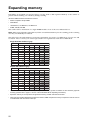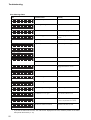
1
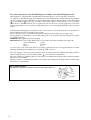
Instructions
Please read these instructions carefully before using this product, and save them for future reference.
International ENERGY STAR® Office Equipment Program
As an ENERGY STAR partner, Canon Electronics Inc. has determined that this product
meets the ENERGY STAR guidelines for energy efficiency.
The International ENERGY STAR Office Equipment Program is an international program
that promotes energy saving through the use of computers and other office equipment.
The program backs the development and dissemination of products with functions that
effectively reduce energy consumption. It is an open system in which business proprietors can participate voluntarily. The targeted products are office equipment such as
computers, monitors, printers, fax machines, copiers and scanners. Their standards and
logos are uniform among the participating nations.
FCC REGULATIONS (For 120V models)
This equipment has been tested and found to comply with the limits for a Class A digital device, pursuant to Part 15 of the FCC Rules. These limits are designed to provide reasonable protection against harmful interference when the equipment is operated in a commercial environment. This equipment generates, uses, and can radiate radio frequency energy and, if not installed and used in accordance with the
instruction manual, may cause harmful interference to radio communications. Operation of this equipment in a residential area is likely to cause harmful interference in which case the user will be required to
correct the interference at his own expense.
Do not make any changes or modifications to the equipment unless otherwise specified in the manual. If
such changes or modifications should be made, you could be required to stop operation of the equipment.
RADIO INTERFERENCE REGULATIONS (For 120V models)
This digital apparatus does not exceed the Class A limits for radio noise emissions from digital apparatus
as set out in the Interference-causing equipment standard entitled "Digital Apparatus", ICES-003 of the
Industry Canada.
RÈGLEMENT SUR LE BROUILLAGE RADIOÉLECTRIQUE (For 120V models)
Cet appareil numérique respecte les limites de bruits radioélectriques applicables aux appareils numériques
de Classe A prescrites dans la norme sur le matériel brouilleur: "Appareils Numériques", NMB-003 édictée
par l'Industrie Canada.
Für EMVG
Dieses Produkt ist zum Gebrauch im Wohnbereich, Geschäfts-und Gewerbebereich sowie in Kleinbetrieben
vorgesehen.
Trademarks
• IBM and PC/AT are registered trademarks of International Business Machines Corporation.
• Microsoft, Windows, and Windows NT are registered trademarks of Microsoft in the U.S. and in other countries.
• ISIS® is a registered trademark of Pixel Translations, a division of Input Software Inc.
• Product names mentioned herein are for identification purposes only and may be trademarks and/or registered
trademarks of their respective countries.
Other Notices
• The information given in these Operating Instructions is subject to change without notice.
English
WARNING:
TO PREVENT FIRE OR SHOCK HAZARD, DO NOT EXPOSE THIS PRODUCT TO RAIN OR ANY TYPE
OF MOISTURE.
THE SOCKET-OUTLET MUST BE NEAR THIS EQUIPMENT AND MUST BE EASILY ACCESSIBLE.
THE PRODUCT SHOULD BE USED ONLY WITH A POWER CORD THAT IS SUPPLIED BY THE MANUFACTURER.
Français
Avertissement:
Pour éviter tout risque d'incendie ou de choc électrique, ne pas soumettre cet appareil à la pluie ou à
l'humidité.
"La prise secteur devra se trouver à proximité de l'appareil et être facilement accessible."
Le produit ne devra être utilisé qu'avec le cordon d'alimentation fourni par le fabricant.
Deutsch
Warnung:
Zur Verhütung von Feuer dem und elektrischem Schlag dieses Erzeugnis nicht Regen oder sonstiger
Feuchtigkeit aussetzen.
Die Steckdose muß nahe bei diesem Gerät angebracht und leicht zugänglich sein.
Dieses Gerät darf nur mit dem vom Hersteller gelieferten Netzkabel verwendet werden.
Für Benutzer in der BRD
Hinweis:
Der arbeitsplatzbezogene Geräuschemissionswert dieses Gerätes beträgt 70 dB(A) nach DIN 45635 Teil 19.
1
For your safety please read the following text carefully. (For United Kingdom only)
This appliance is supplied with a moulded three pin mains plug for your safety and convenience.
A 5 amp. fuse is fitted in this plug. Should the fuse need to be replaced please ensure that the replacement
fuse has a rating of 5 amps. and that it is approved by ASTA or BSI to BS1362. Check for the ASTA mark
or the BSI mark
on the body of the fuse. If the plug contains a removable fuse cover you must
ensure that it is refitted when the fuse is replaced. If you lose the fuse cover the plug must not be used
until a replacement cover is obtained. A replacement fuse cover can be purchased from your local Canon
Dealer.
If the fitted moulded plug is unsuitable for the socket outlet in your home then the fuse should be removed and the plug cut off and disposed of safely.
There is danger of severe electrical shock if the cut off plug is inserted into any 13 amp. socket.
If a new plug is to be fitted please observe the wiring code as shown below. If in any doubt please consult
a qualified electrician.
WARNING: This appliance must be earthed.
IMPORTANT: The wires in this mains lead are coloured in accordance with the following code.
Green-and-Yellow:
Earth
Blue:
Neutral
Brown:
Live
As the colours of the wire in the mains lead of this appliance may not correspond with the coloured
markings identifying the terminals in your plug, proceed as follows.
The wire which is coloured Green-and-Yellow must be connected to the terminal in the plug which is
marked with the letter E or by the Earth symbol
or coloured Green-and-Yellow.
The wire which is coloured Blue must be connected to the terminal in the plug which is marked with the
letter N or coloured Black.
The wire which is coloured Brown must be connected to the terminal in the plug which is marked with
the letter L or coloured Red.
How to replace the fuse:
Open the fuse compartment with a screwdriver and replace the fuse.
FUSE
2
General safety warnings
Always follow these general safety warnings to prevent personal injury.
Working around the scanner
Follow these warnings while working around the scanner.
• To avoid the hazards of fire and electrical shock, never expose this device to rain or any type of moisture.
• To avoid the hazard of fire, never block the fan exhaust vent.
• Never install and operate the scanner near flammable substances such as alcohol, thinner, acetone, or any other
type of volatile material.
• Never damage or modify the power cord and never place heavy objects on the power cord.
• To avoid severe electrical shock, make sure that your hands are dry before you handle the power cord.
• This product emits low level magnetic flux If you use a cardiac pacemaker and feel abnormalities, please be away
from this product and consult your doctor.
• Never plug the scanner power cord plug into a multi-plug power strip.
• Never bundle, wrap, or tie the power cord around itself or another object.
• Connect the power plug securely to the power source and make sure no part of the metal plug is exposed.
• Use only the power cord and plug provided with the scanner.
• To avoid serious injury or damage to the scanner, never disassemble the scanner. Some parts inside the scanner
become extremely hot and carry high voltage.
• Never use flammable aerosol products near the scanner, such as adhesive sprays, air fresheners, insect repellent, etc.
• Before cleaning the scanner, always switch off the power and disconnect the scanner power cord from the power
source.
• Use only a soft, damp cloth soaked in water and a small amount of mild detergent to clean the scanner. Wring the
cloth completely before you wipe the exterior of the scanner.
• If you hear strange sounds, sense vibration, or smell odd odors around the scanner, switch the scanner off immediately and disconnect the power cord from the power source. Call for service immediately.
• To avoid damage from shock and vibration, always have two people lift or carry the scanner. If you suspect that the
unit has been accidentally damaged, switch the scanner off and immediately disconnect the power cord from the
power source. Call for service.
• Before lifting or moving the scanner, always switch the scanner off and remove the power cord from the power
source.
• WARNING! TO AVOID DAMAGE TO YOUR EYES, NEVER LOOK DIRECTLY INTO THE SCANNING LIGHT.
3
General operating precautions
Never use this scanner for the following illegal purposes.
• Copying currency, coins, securities.
• Copying copyrighted material for any purpose other than personal reference.
• Copying any kind of public or private document issued and controlled by law birth certificates, operator licenses,
passports, etc.
Follow these simple precautions while working around the scanner.
• Never place the scanner on an unstable or vibrating surface.
• Keep all liquids; beverages, away from the scanner. If you accidentally spill something into the scanner, switch the
power off immediately, disconnect the power cord from the power source, and call for service.
• Keep small objects like paper clips, pins, staples, etc. away from the scanner. Before you scan a document, make
sure all fasteners have been removed from the documents that you are going to scan.
• Place the unit in a clean room subject to comfortable ranges of heat and humidity. Avoid dusty air and high humidity.
• To avoid breaking the document glass, never place anything on top of the scanner.
• Before connecting the power cord to the scanner, confirm that the power source meets the rated power specifications
printed on the name plate of the scanner.
• When you remove the power cord from the power source, grip it by the plug. Never pull on the cord to remove the plug
from the socket.
• Keep the area around the power source clear of all obstacles so you can disconnect the power cord easily in case of
an emergency.
• When the scanner is not in use, switch it off. If the scanner is not going to be used for a long period, switch it off and
disconnect the power cord from the power source.
• Avoid wearing loose fitting clothing, dangling jewelry, or long ties which could become entangled with moving parts
like the feed rollers.
• Some parts inside the scanner become extremely hot during operation because they are subjected to high voltage.
Avoid touching any part inside the scanner during cleaning or paper jam removal.
• To prevent electrical shock, avoid wearing metal jewelry when cleaning the scanner or removing a paper jam.
4
Table of contents
General safety warnings --------------------- 3
Cleaning the scanner ------------------------ 41
Working around the scanner ----------------------- 3
Cleaning the scanner exterior -------------------- 41
Cleaning the scanner interior -------------------- 41
Cleaning the paper feed rollers -------------- 41
Cleaning the scanning path ------------------ 44
Cleaning the cover sheet and document
glass ------------------------------------------------ 48
Attaching the sensor roller -------------------- 49
General operating precautions ------------- 4
Before you begin ------------------------------- 6
Welcome! ------------------------------------------------ 6
Outstanding features --------------------------------- 6
Conventions -------------------------------------------- 7
Important terms you should know ----------------- 7
Choosing a location for the scanner -------------- 7
Unpacking the scanner ------------------------------ 9
About the metal clamp ----------------------------- 10
Important parts of the scanner ------------------- 11
What is on the display panel? -------------------- 13
How to use the display panel ---------------- 13
What is on the LCD? --------------------------- 14
Expanding memory -------------------------- 50
Troubleshooting ------------------------------- 51
Specifications ---------------------------------- 53
Index --------------------------------------------- 54
Setting up the scanner ---------------------- 15
Connecting the scanner --------------------------- 15
Switching the scanner on/off --------------------- 16
Selecting the display language ------------------ 17
Setting how the scanner operates -------------- 18
Setting the scan mode ------------------------- 18
Setting the counter ----------------------------- 23
Setting the imprinter ---------------------------- 25
Performing SCSI and other settings
with the Others menu -------------------------- 27
Operating the scanner----------------------- 30
Using the ADF --------------------------------------- 30
ADF loading guidelines ------------------------ 30
Documents you should never load
in the ADF ---------------------------------------- 30
Loading documents in the ADF ------------- 31
Feeding a document manually
from the ADF ------------------------------------- 34
Using the flatbed to scan documents ---------- 35
Loading the flatbed ----------------------------- 35
Loading the flatbed for repeated scanning 37
Using control sheets --------------------------- 38
Clearing paper jams -------------------------------- 39
Removing a jammed paper from the feed
slot -------------------------------------------------- 39
Removing a paper jam from the paper
output slot ----------------------------------------- 40
5
Before you begin
Welcome!
Thank you for purchasing a Canon Document Scanner DR-4580U.
These instructions show you how to operate and maintain the Canon Document Scanner DR-4580U. Before
you use the scanner, read these instructions. Keep these instructions and all the other documents you received with the scanner in a safe place where you can find them for future reference.
Outstanding features
Here is a brief summary of the outstanding features of your new scanner.
Enhanced Scan
Scanning quality is enhanced by providing an optical resolution of 400 dpi and gray scale scanning capability.
High-speed document feeding
The Automatic Document Feeder (ADF) delivers high-speed scanning on standard paper sizes up to A3
(297 × 420 mm) up to 53 sheets per minute (scanning A4 size, single-sided documents). Scanning documents placed on the flatbed is also extremely fast.
Flatbed scanning
The flatbed allows you to scan bound documents and originals that are too thin or fragile to feed from the
ADF.
Variety of scanning modes
The following modes can be selected for scanning jobs.
• Single-sided or double-sided documents
• Automatic feed of stacked documents or single manual feed
• Text (black and white) or photo (gray scale) mode scanning
Variety of image processing methods
The following processing methods can be applied to images as they are scanned:
• Dynamic Threshold
• Dither
• Image Emphasis
• Reverse Image
• Mirror Image
• Noise Reduction
• Automatic Separation
• Remove Shadow
Double-feed detection
Immediate detection of double-feeds pauses the scanning job and allows you to correct the problem with
having to remove jammed sheets from the scanner.
Skewed feed detection
This function detects skewed document feed and stops feeding to allow the problem to be corrected.
6
Before you begin
Conventions
The following conventions are used in this manual.
(➞12)
A number enclosed in parentheses refers to a page number that contains more information about the previous sentence or paragraph.
Note:
Notes provide tips about procedures and how to avoid minor difficulties.
Caution!
Cautions alert you to procedures or circumstances that you should avoid in order to
prevent damage to the scanner.
WARNING!
WARNINGS ALERT YOU TO DANGERS THAT COULD LEAD TO SERIOUS PERSONAL INJURY.
Important terms you should know
Here is a list of a few important terms you should know before you use this manual.
ADF
ADF denotes Automatic Document Feeder, the device on the scanner that allows you to load stacks of
documents for continuous scanning.
CIS
Contact Image Sensor, used to scan the back sides of originals.
document
The documents that you scan from the ADF or the flatbed of the scanner.
parent software application
The software application that you use to operate the scanner. The scanner operates with ISIS or TWAIN
compliant software application.
Choosing a location for the scanner
Follow these recommendations on these checklists when you select a location for the scanner.
Carrying the scanner
• At least two people should lift and position the scanner for setup.
• If you have just transported the scanner from a cold location into a warm room, wait at least 1~2 hours before you
set up and switch on the scanner. Exposing the scanner to a sudden change in temperature could cause condensation to build up inside the scanner and adversely affect its performance. Allow time for the internal parts to
become perfectly dry.
7
Before you begin
General Location
• Make sure there is enough space around the scanner as shown in the illustration.
250 mm (9.8")
200 mm (7.9")
300 mm (11.8")
• The scanner should not be exposed to direct sunlight. If this is unavoidable, install heavy curtains on the windows.
• The area around the scanner should be free of dust, fumes, and water vapor.
• The area around the scanner must be well ventilated when using volatile fluid to clean the rollers inside.
• Never place the scanner near running water, a heat source, or in an area like a laboratory exposed to volatile,
corrosive, flammable chemicals like ammonia, acetone, benzene, etc.
• Set up the scanner in a room that is well within a comfortable range of temperature and humidity, and not subject
to rapid changes in temperature or humidity.
Room temperature
15°C to 30°C (59°F to 86°F)
Relative humidity
30% to 80% RH
• Place the scanner on a clean, flat, stable surface free of vibration and shocks.
• Never place the scanner near office equipment or an appliance that generates a strong magnetic field. The electrical “noise” from such a device could interfere with operation of the scanner.
• Never attempt to place or operate the scanner in a vertical position.
• To avoid poor performance caused by static electricity, never operate the scanner on top of a carpet.
Power source
• Use a power source with a voltage level that does not vary more than 10% from the voltage level marked on the
name plate (located on the back side of the scanner).
• Set up the scanner close to an independent power source. Do not plug the scanner power cord into a power outlet
that is shared by other devices or equipment.
• Keep the area around the power outlet free of obstructions in case you need to unplug the power cord quickly in an
emergency.
Power cord
• Use only the power cord supplied with the scanner and do not use an extension cord.
• Do not use a line conditioner, transient suppressor or surge protector.
• Never bundle the power cord or wrap the power cord around an object like a table leg.
• Keep the power cord free. Never place heavy objects on top of the power cord.
8
Before you begin
Unpacking the scanner
Check each item against the list below as you remove it from the box. If any item is missing, contact the
supplier.
Power cord
Document Scanner DR-4580U
Blower
Manuals
License Agreement
ISIS/TWAIN Driver
Operating Instructions
Warranty
Setup CD-ROM
Registration card
Note: Save the original box and packing material for re-packing the scanner if you need to transport it.
9
Before you begin
About the metal clamp
To avoid damage during shipping, the optical unit of the scanner is secured with a metal clamp. Before
moving or installing the scanner, you must install the metal clamp in the specified position.
If you fail to install the metal clamp in the specified position when setting up the scanner, a warning
message will be displayed on the LCD and you will not be able to use the scanner.
1
Pull the scanner out 15 cm (6 in.) over
the edge of a desk or worktable as
shown in the illustration.
15 cm
(6 in.)
No more than 15 cm!
Caution!
•
•
2
To prevent the scanner from falling, do not allow the scanner to overhang the edge of the
table by more than 15 cm (6 in.)
To avoid damaging the scanner, never turn it upside down or lay it on its side.
When moving the scanner, install the
metal clamp on the bottom of the
scanner at position ➀, and when setting up and using the scanner, install
the clamp at position ➁.
➀
➁
Metal clamp
Screw
10
Before you begin
Important parts of the scanner
Hopper
ADF door release
Document guide
(Inside ADF door)
Document cover
ADF door
Front door
Display panel
Displays short messages
when performing settings.
Manual feed selector
Exit substopper
Front door release
Power indicator
(Inside the front door)
The green lamp lights when
the power is turned on.
When an error occurs, the
color changes to red
(steady or flashing). In the
sleep mode, the color
changes to flashing orange.
Exit document stopper
Hopper extension tray
Imprinter door
(top door)
Open this door to install
the imprinter or ink
cartridge.
Connectors
Connect the scanner and
host computer.
Power switch
| On
O Off
AC inlet
Power cord
Fan exhaust vent
11
Before you begin
With the document cover open
Cover sheet
(white sheet)
Standard mark
Document glass (Flatbed)
With the ADF open
CIS glass
Scanning section glass
12
Before you begin
What is on the display panel?
You can use keys and display panel message to set up scanning jobs.
Scan
Counter
Imprint
Others
DR - 4580U
Mode
Ready/Error
Home
Start / Stop
Select
Menu keys
Select keys
Mode keys
Start/Stop key
Liquid Crystal Display (LCD)
How to use the display panel
Press the keys to use the display panel.
Scan
Scan
R e a d y
Opens the Scan setting menu on the
LCD.
LCD
Counter
The LCD displays menu settings and
messages (up to 32 characters wide).
Counter
Opens the Counter setting menu to
you can set the number of documents
to scan.
Mode keys
▲
Imprint
Opens the imprint menu so you can
stamp scanned documents.
▼
Others
Home
Home
Saves the settings you have performed in the menu, closes the menu,
and returns the scanner to the standby mode. You can also use this key to
change the display language.
Start / Stop
▼
Displays the previous mode in the
selected menu.
Others
Opens the Others menu so you can set
the SCSI device numbers and perform
other important settings.
▲
Displays the next mode in the selected
menu.
Imprint
Select keys
Displays the next value in the selected
mode.
Displays the previous value in the
selected mode.
Start/Stop
Starts or stops a scanning job.
13
Before you begin
What is on the LCD?
The LCD displays the messages about the scanner status during scanning jobs and displays the menus
and settings for the menu setup mode.
The Ready message (stand-by mode)
The Ready message tells you that the scanner is standing by and ready for operation. After changing
menu settings, or before starting a scanning job, make sure “Ready” is displayed in the LCD.
R e a d y
Sleep message
The Sleep message appears when the scanner goes into the sleep mode. (➞ 29)
S l e e p
Error messages
When a problem occurs with the scanner, a message is displayed in the LCD. For details, refer to the error
message table. (➞ 52)
Error message display
U 1 1
J A M
✕ ✕ ✕ ✕ ✕ ✕ ✕ ✕
Other messages
Message
What it means
S c a n n i n g . . .
1
Displayed from the beginning to the end of a scanning
job.
When the job is finished, “Ready” is displayed.
S t o p p i n g . . . W a i t !
1 2 3 4 5 6
Displayed immediately after pressing Start/Stop during
a scanning job.
When the Start/Stop key is pressed during a scanning
job, the job is cancelled.
If you press Start/Stop again after stopping scanning to
perform scanner settings, the settings display returns.
S c a n n e r
S t o p p e d
1 2 3 4 5 6
Displayed after pressing the Start/Stop key and scanning stops.
Even if a document is still in the scanner, the JAM
message is not displayed. Open the ADF door and ADF
to remove the document in the scanner.
After the document in the scanner is removed, the Ready
message is displayed.
P r e s s
S T A R T
K e y
1
14
Displayed after the software application has been set to
start scanning at the press of the Start/Stop key. After
setting the document for scanning, press the Start/Stop
key to start the scanning job.
Setting up the scanner
Follow the instructions in this section to set up the scanner. Before you set up the scanner, make sure that
you have:
• Prepared a suitable location for the scanner (➞ 7)
• Unpacked the scanner and made sure that you have everything (➞ 9)
• Read all the precautions regarding safe use of the scanner (➞ 3 to 4)
Connecting the scanner
Follow this procedure to connect the scanner to the computer.
1
Connect the SCSI cable and power
cord as shown in the illustration.
SCSI connectors
• Use only the power cord supplied with
the scanner.
• Confirm that the SCSI cable is a
shielded cable.
• The scanner uses a half-pitch 50-pin
(pin-type) SCSI connector. When connecting the SCSI connector to another
device, such as a computer, select a
SCSI interface cable that is equipped
with the appropriate connector types.
• If the power cord has already been
connected, make sure the scanner is
switched off then disconnect the power
cord from the back of the scanner.
2
SCSI interface
cable
AC inlet
Power cord
Make sure that the fan exhaust vent
is not blocked. There should be at
least 250 mm (9.8 in.) of open
space behind the scanner.
To power source
250 mm (9.8")
200 mm (7.9")
WARNING!
To PC
300 mm (11.8")
THE SCANNER COULD BECOME EXTREMELY HOT IF THE FAN EXHAUST
VENT IS BLOCKED, RESULTING IN A FIRE. MAKE SURE THIS AREA IS CLEAR
AT ALL TIMES.
3
Turn on the scanner’s power. (➞ page 16)
4
Power on the computer.
• Be sure to turn on the scanner’s power before turning on the power to the computer.
When using daisy chain connection including other SCSI devices, check the SCSI ID and
terminator settings. (➞ page 27 to 28)
• If you are using Windows 95/98/Me, Windows 2000 or Windows XP, then the first time that you
turn on your PC after connecting this scanner to your PC Windows’ Plug and Play function will
automatically display a screen prompting you to install the scanner driver. (The name of this
prompt screen varies among the different versions of Windows.)
In the case of “New Hardware Found” (Windows 95), select “Select from a list of alternative
drivers” and click OK. On the next screen, select Other Devices and then click OK.
15
Setting up the scanner
In the case of “Update Device Driver Wizard” (Windows 95), click Next and then click Finish on
the next screen.
In the case of “Add New Hardware Wizard” (Windows 98), follow the procedure described
below.
1. Click Next.
2. Select “Search for the best driver for your device (Recommended)” and then click next.
3. Clear all checkmarks and then click Next.
4. Click Next.
5. Click Finish.
In the case of “Add New Hardware Wizard” (Windows Me), select “Automatic search for a
better driver (Recommended)”, then click Next and then click Finish on the next screen.
In the case of “Found New Hardware Wizard” (Windows 2000), follow the procedure described
below.
1. Click Next to advance to the “Install Hardware Device Drivers” screen.
2. Select “Search for a suitable driver for my device (recommended)”, and then click Next to
proceed to the “Locate Driver Files” screen.
3. Clear all of the checkmarks in the “Optional search locations”, and then click Next to proceed to the “Driver Files Search Results” screen.
4. Select “Disable the device.” and then click Finish.
With the “Found New Hardware Wizard” (Windows XP), select “Install the software automatically (Recommended)”, then click Next, select “Don't prompt me again to install this software”,
and click Finish.
• You must install the scanner driver before using the scanner. Refer to the “ISIS/TWAIN Driver
User’s Manual.”
Switching the scanner on/off
1
To power the scanner on, press the
power switch to the on position (|).
The power lamp flashes green while the
scanner warms up. When the power
lamp lights green and remains on, the
scanner is ready for operation.
2
To power the scanner off, press the
power switch to the off position (O).
The power lamp extinguishes.
Power switch
16
Setting up the scanner
Selecting the display language
Follow this procedure if you want to select another language for the message displays. Three languages
are available: Japanese, English, and German.
Scan
Counter
Imprint
Others
DR - 4580U
Mode
Ready/Error
Home
Start / Stop
Select
2, 4
1
2
3
4
3
If the scanner is on, switch it off.
Press and hold down the Home key,
then switch on the scanner. Release
the Home key when you see the
message “High Speed Scanner” in
the LCD, then wait until the language selection display appears.
S e t
L a n g u a g e
E n g l i s h
L e t t e r
Press the up or down mode keys
(
) to display the name of the
language of your choice.
S e t
L a n g u a g e
E n g l i s h
Press the Home key and release it.
R e a d y
A 4
The language selection is saved and the
Ready message is displayed in that language.
17
Setting up the scanner
Setting how the scanner operates
Before each scanning job, you can set up operation parameters that determine how the scanner operates. In
this section, we will show you how to open and use the menus to perform operation settings.
Setting the scan mode
Press the Scan key to open the Scan menu and select the scanning density, scanning speed, and other
settings that determine the conditions of the scanning job. Selecting a setting other than Host will invalidate any settings made by the application running on your host computer.
Display panel
1
Scan
Counter
Imprint
Others
DR - 4580U
Mode
Ready/Error
Home
Start / Stop
Select
4
1
2
3
4
2
Press the Scan key.
0 1 . F . B r i g h t n e s s
D – – – – + – – – – L
H o s t
Press the up or down Mode arrow
key (▲ ▼) to display the scanning
mode that you want to select.
(➞ 19)
0 8 . B . C o n t r a s t
L – – – – + – – – – H
H o s t
Press the right or left Select key
(
) to display the settings for the
selected mode.
0 8 . B . C o n t r a s t
L – – * – + – – – – H
To save the setting and return to
standby (Ready) press the Home
key.
-orIf you want to perform other settings
before returning to standby, press
the desired menu key.
R e a d y
Counter
Imprint
Others
➞ 24
➞ 26
➞ 28
Then press the right or left Select key (
18
3
) to select the settings.
L 2
Setting up the scanner
Summary of the Scan menu modes and settings
Number, mode and
default display
Content
01 Front side brightness
0 1 . F . B r i g h t n e s s
D – – – – + – – – – L
H o s t
Selects scanning density for the front side of document pages.
D4
D3
D2
D1
Norm
L1
L2
L3
L4
Host
D means Dark, L means Light.
Pressing
02 Front side image emphasis
0 2 . F . E m p h a s i s
H o s t
– – – + –
or
with Host displayed, changes the display to Norm.
Sets emphasis for the front side of document pages.
Smooth
None
Low
Medium
High
Host
Pressing
or
with Host displayed, changes the display to Medium.
Sets the contrast for the front side of document pages.
03 Front side contrast
0 3 . F . C o n t r a s t
H o s t
L – – – – + – – – – H
L4
L3
L2
L1
Norm
H1
H2
H3
H4
Host
H means high, L means Low.
Pressing
or
with Host displayed, changes the display to Norm.
Sets gradation for the front side of document pages.
04 Front side halftone
0 4 . F . H a l f t o n e
H o s t
Host
Binary
Bayer dither 64
Halftone dot 32
Bayer dither 16
Halftone dot 64
Error diffusion
(Dynamic Th.)
“Dynamic Threshold” does not appear if expansion memory (DIMM) is
not installed. To use “Dynamic Threshold”, contact your service
representative for installation of expansion memory (DIMM).
05 Back side dropout color
0 5 . F . C o l o r
d r o p
H o s t
06 Back side brightness
0 6 . B . B r i g h t n e s s
H o s t
D – – – – + – – – – L
Set the dropout color for the back side of document pages.
Host
Red
Green
Sets the density for the back side of document pages.
D4
D3
D2
D1
Norm
L1
L2
L3
L4
Host
D means Dark, L means Light.
Pressing
07 Back side image emphasis
0 7 . B . E m p h a s i s
H o s t
– – – + –
or
with Host displayed, changes the display to Norm.
Sets emphasis for the back sides of document pages.
Smooth
None
Low
Medium
High
Host
Pressing
or
with Host displayed, changes the display to Medium.
19
Setting up the scanner
Number, mode and
default display
Content
Sets the contrast for the back side of document pages.
08 Back side contrast
0 8 . B . C o n t r a s t
L – – – – + – – – – H
H o s t
L4
L3
L2
L1
Norm
H1
H2
H3
H4
Host
Pressing
or
with Host displayed, changes the display to Norm.
Sets the gradation for the back side of document pages.
09 Back side halftone
0 9 . B . H a l f t o n e
H o s t
Host
Binary
Bayer dither 64
Halftone dot 32
Halftone dot 64
Bayer dither 16
Error diffusion
(Dynamic Th.)
“Dynamic Threshold” does not appear if expansion memory (DIMM) is
not installed. To use “Dynamic Threshold”, contact your service
representative for installation of expansion memory (DIMM).
Sets the rate of noise reduction (speckling) in scanned document
10 Noise reduction
1 0 . N o i s e
+ – – – – – –
R e d u c t .
H o s t
image.
Host
None
B4✕4
B5✕5
W3✕3
W4✕4
B1✕1
B2✕2
B6✕6
W1✕1
W5✕5
B3✕3
W2✕2
W6✕6
B1 ✕ 1~B6 ✕ 6 : Scanner reduces a black dot.
W1 ✕ 1~W6 ✕ 6 : Scanner reduces a White dot.
When enabled removes the black lines that appear at the top and
11 Black line removal
1 1 . B L K
L i n e
R e m o v e
bottoms of scanned images.
H o s t
Host
Disable
Enable
Sets scanning for actual document size or reduced.
12 Scanning mode
1 2 . S c a n n i n g
M o d e
H o s t
Host
Fit to Page
Actual
Actual scans at 100% actual page size. Some data on page edges may
be lost.
Fit to Page shrinks image to fit scanned page.
13 Double feed detection
1 3 . D o u b l e
F e e d
H o s t
Switches automatic double feed detection off and on.
Host
Not detect
Detect
When set to Detect, the scanner buzzes an alert and the power lamp
flashes red if double feeding is detected. Even if set to OFF for Setting
the Buzzer, it will still buzz an alert.
When scanning important documents, confirm that the number of
scanned pages displayed on the LCD matches the number of actual
pages.
Double feed detection will not work if paper is less than 210 mm in length.
When documents of differing thicknesses are loaded, double feed
detection does not work.
20
Setting up the scanner
Number, mode and
default display
Content
14 Double Feed Action
1 4 . D o u b l e
A c t i o n
F e e d
B u z z e r
Sets the action that occurs when double feed is detected for a
document.
Host
Stop
Buzzer
Host/Buzzer: The buzzer sounds, but feeding continues. An error is
displayed when feeding is completed.
Stop:
15 Setting the sensitivity of
double feed detection
1 5 . D o u b l e
F e e d
S e n s .
H o s t
The buzzer sounds, feeding stops, and an error is displayed.
Sets the degree of sensitivity for the double feed detector.
Sens. Host
Normal Sens
Low sensitivity
High sensitivity
High sensitivity: Select if you experience double feeds that jam the
scanner and the buzzer does not sound.
Low sensitivity:
Sets the scanning speed.
16 Feed speed
1 6 . F e e d
S p e e d
H o s t
17 Detect skew
1 7 . D e t e c t
S k e w
D e t e c t
18 Save scanning conditions
(memory selection)
1 8 . S a v e
S e t t i n g
M e m o r y
1
18 Save scanning settings
(Execution)
1 8 . S a v e
Select if the buzzer sounds when no double feed occurs.
S e t t i n g
E x e c = < >
Host
Slow
Normal
Fast
Determines whether the scanner detects skewed document feed
when pages feed into the ADF at an angle.
Detect
Not detect
Detect:
Skewed feed is detected and paper feed is stopped.
Not detect:
Skewed feed is not detected.
Selects the memory bank to which scanning conditions 01 to 17
are saved.
Memory 1
Memory 2
Pressing
keys simultaneously saves scanning conditions 01
to 17 in the memory selected for “Save Scanning Settings”
(Select Memory).
“Completed” displayed after saving.
21
Setting up the scanner
Number, mode and
default display
19 Load scanning settings
1 9 . L o a d
S e t t i n g
D e f a u l t
Content
Loads the scanning settings from Memory 1 or Memory 2.
Default
Memory 1
Memory 2
Use the or key to select Memory 1 or Memory 2. The saved settings
for scanning are enabled with the “Save Scanning Settings” execution.
If other settings have been saved in another memory, you can change
the settings easily during scanning.
This setting is not changed even if the power is switched off and on.
If “Default” is selected, all the saved scanning settings will be reset to
their default values.
Note
• When scanning confidential documents, make sure that the number of pages scanned displayed in the LCD matches
the actual number of pages scanned.
• The double-feed detection warning may be set off by thick or creased documents, pages with correction fluid on
them, and document pages with punched holes. When scanning these types of documents, you should set the
sensitivity for double feed detection Low (15).
• Double feed detection may not operate correctly when scanning documents shorter than 210 mm (8.3 in.), i.e. A5
size documents.
• After changing settings 01 to 17, execute “18 Save scanning settings” to save the changes. If the settings are not
saved before the scanner is switched off, all the changes will be cleared and the previous settings will be restored.
22
Setting up the scanner
Setting the counter
Press the Counter key to open the Counter menu and select the method of counting scanned document
pages. If your software application is capable of performing these settings, you do not need to perform
the settings manually with the display panel.
Display panel
Scan
Counter
Imprint
Others
DR - 4580U
Mode
Ready/Error
Home
Start / Stop
Select
4
1
2
3
4
1
3
2
Press the Counter key.
0 1 . D i s p . C o u n t e r
S c a n
Press the up or down Mode arrow
key (▲ ▼) to display the setting that
you want to select. (➞ 24)
0 2 . U s e r
Press the right or left Select key
(
) to display the settings for the
selected mode.
0 2 . U s e r
To save the setting and return to
standby (Ready) press the Home
key.
-orIf you want to perform other settings
before returning to standby, press
the desired menu key.
R e a d y
Scan
Imprint
Others
C o u n t e r
0
C o u n t e r
+ 1
➞ 19
➞ 26
➞ 28
Then press the right or left Select key (
finished.
) to select the settings then press the Home key when you are
23
Setting up the scanner
Summary of the Counter menu modes and settings
Number, mode and
default display
Content
01 Select the counter
displayed on LCD
0 1 . D i s p . C o u n t e r
S c a n
Selects the method for counting the number of sheets scanned.
The counter selected here is displayed on the LCD during
scanning. When using the optional imprinter unit, the number
can also be printed on documents scanned.
Scan
User
System
Scan:
The number of document pages scanned is counted
starting with 1. The counter is cleared each time scanning is
completed
User:
The number of pages scanned is counted using the counter
and increment values selected in "02. User counter".
This setting is cleared with the scanner's power is turned
off. This counting method is useful for numbering pages
when scanning documents that are too large to be counted
in one batch.
System:
The value of the system counter is displayed.
Example using the User counter
(with a counter value of 301 and in increment of +2):
Pages actually scanned:
Counter display:
2,
3,
4,
5,
6
305,
307,
309,
311,
313
Selects the default number (0-9999999) before scanning.
02 Setting the user counter
0 2 . U s e r
1,
303,
Press
C o u n t e r
0
to increase the user counter by one. Press
crease the user counter by one.
Pressing and holding down
value in units of 10.
02 Setting the User
Counter Extender
0 2 . U s e r
C o u n t e r
+ 1
once to de-
or
rapidly increases or decreases the
Selects increment number for the extender in the default
number.
+1
+2
+3
••••••
+7
+8
+9
Press once to increase user counter extender by one. Press
to decrease the user counter extender by one.
02 Clear the User Counter
0 2 . U s e r
C o u n t e r
C l e a r = < >
03 Displaying the system counter
0 3 . S y s t e m
24
C o u n t .
1 2 3 4 5 6 7
once
Clears the counter set by the user.
Press
together to clear the user counter.
“Completed” displayed when counter is cleared.
Displays the total amount of scanned documents up to now.
Setting up the scanner
Setting the imprinter
Use the Imprint key to open the Imprint menu and define text that can be used to stamp the front pages
of scanned documents. Selecting a setting other than Host will invalidate any settings made by the application running on your host computer.
Note: However, this feature is not available if the optional Imprinter is not installed.
Display panel
4
Scan
Counter
Imprint
Others
DR - 4580U
Mode
Ready/Error
Home
Start / Stop
Select
1
1
2
3
4
3
2
Press the Imprint key.
0 1 . P r e
Press the up or down Mode arrow
key (▲ ▼) to display the setting that
you want to select. (➞ 26)
0 2 . P r e
P o s i t i o n
1 0 . 0 mm
<
0 C h a r >
Press the right or left Select key
(
) to display the settings for the
selected mode.
0 2 . P r e
P o s i t i o n
1 2 . 4 mm
<
1 C h a r >
To save the setting and return to
standby (Ready) press the Home
key.
-orIf you want to perform other settings
before returning to standby, press
the desired menu key.
R e a d y
Scan
Counter
Others
I m p r i n t
H o s t
➞ 19
➞ 24
➞ 28
Press the right or left Select key (
finished.
) to select the settings then press the Home key when you are
25
Setting up the scanner
Summary of the Imprinter menu modes and settings
Number, mode and
default display
01 Setting the imprinter data
0 1 . P r e
I m p r i n t
H o s t
02 Setting the imprinter
start position
0 2 . P r e
P o s i t i o n
1 0 . 0 mm
<
0 C h a r >
Content
Uses the imprinter to stamp the front sheet of each scanned page
with text you specify.
Host
Count
Host:
Prints the text specified with the software application on the
computer.
Count:
Prints according to the counter setting for “Select the counter
displayed on LCD”. (Counter menu, mode 01)
Specifies the starting location of the stamp printed by the
imprinter if Count was selected for 01 above.
Press a select arrow key (
) to specify the position on the page where
the stamp will print. If zero is entered, the stamp prints 10 mm from the
top edge of the page.
Example: 2 Letter Text Setting
0 2 . P r e
P o s i t i o n
1 2 . 4 mm
<
1 C h a r >
The mm setting tells you the approximate distance of the starting position from the top of the page.
Enter a text string 0 (10 mm or 0.4 in.) to 72 characters wide (182.8 mm
or 7.2 in.)
Here is an illustration of the example above. The two letters print 14.8
mm (0.6 in.) from the top.
Top of the paper
10mm
(0.4in.)
[
[
[
14.8mm
(0.6in.)
4580
4580
[
[
[
Top of the printout when
the imprinter start position
is set to 2 characters.
Spaces fill out stamps shorter
than 7 characters.
The count must be printed with 7-digit numbers. Numbers shorter than
7-digits are counted as spaces and not printed.
R o t a t e
H o s t
Prints portrait orientation.
90°
Rotates character string 90 degrees and prints.
AB
A
B
0°
180°
Print portrait orientation from the end of
the character string.
270° Rotates character string 270 degrees and prints.
AB
0 3 . P r e
This sets the orientation of character printing when using the
imprinter.
Host
0°
90°
180°
270°
A
B
03 Setting the imprinter Orientation
:Transfer direction
26
Setting up the scanner
Performing SCSI and other settings with the Others menu
Use the Others key to open the Other menu to define the SCSI ID for the scanner, terminator setting,
buzzers sound setting, confirm the scanner version number, and so on.
Note: These settings can be performed only with the scanner display panel.
Display panel
4
Scan
Counter
Imprint
Others
DR - 4580U
Mode
Ready/Error
Home
Start / Stop
Select
1
1
2
3
4
3
2
Press the Others key.
0 1 . V e r s i o n
Press the up or down Mode arrow
key (▲ ▼) to display the setting that
you want to select. (➞ 28)
0 2 . B u z z e r
Press the right or left Select key
(
) to display the settings for the
selected mode.
0 3 . S C S I
To save the setting and return to
standby (Ready) press the Home
key.
-orIf you want to perform other settings
before returning to standby, press
the desired menu key.
R e a d y
Scan
Counter
Imprint
O N
I D
N o . 0
➞ 19
➞ 24
➞ 26
Press the right or left Select key (
finished.
) to select the settings then press the Home key when you are
27
Setting up the scanner
Summary of the Others menu modes and settings
Number, mode and
default display
Content
01 Checking the firmware version
0 1 . V e r s i o n
Displays the firmware version of the mechanical control and
imprinter.
xxxM:
Amount of expansion memory installed in the scanner. Does
not appear if no expansion memory is installed.
Mx.xx:
Mechanical control firmware version.
Fx.xx:
Firmware version of the imprinter. Does not appear if the
optional imprinter is not installed.
Switches the scanner buzzer alert off and on.
02 Setting the buzzer
ON
0 2 . B u z z e r
OFF
O N
When the buzzer is on:
1 buzz:
1 buzz:
Long buzz after every scanning job completes normally.
5 buzzes:
Error
Sets the SCSI ID number for the scanner.
03 Setting the SCSI ID
0 3 . S C S I
Short buzz every time a key is pressed.
No.0
I D
No.1
No.2
No.3
No.4
No.5
No.6
No.7
N o . 0
After you select a number for the SCSI ID number, press Home then
switch the scanner off and switch it on again.
04 Setting the terminator
0 4 . T e r m i n a t o r
D i s a b l e
Activates and deactivates the terminator.
Disable
Enable
Select Enable if the scanner is the last device on the SCSI device chain.
Even if Enable is selected, the scanner’s terminator does not function
when the power is turned off. In this case, connect a standard SCSI
terminator if you will be using the computer with the scanner powered
off.
Changes in this setting become effective after the power is cycled off
and on.
05 Setting the transfer rate
0 5 . T r a n s f e r
R a t e
2 0 M B y t e / s e c
20MByte/sec
10MByte/sec
Changes the maximum synchronous transfer rate of the SCSI interface.
If the computer does not detect the scanner or you encounter problems with scanning, try lowering the synchronous transfer rate to 10
Mbyte/sec.
06 Checking the Clean Roller
Warning status
Tells you when it is time to clean the rollers. When this display
nears 100% clean the rollers.
0 6 . C l e a n
W a r n i n g
100%: Rollers must be cleaned. (➞ 41)
R o l l e r
0 %
06 Clearing the Clean Roller
Warning
0 6 . C l e a n
R o l l e r
C l e a r = < >
W a r n i n g
28
0%:
Press
Displayed after setting is cleared (see 06 below).
together to clear the Clean Roller Warning. After the
warning is cleared and reset to 0%, “Completed” is displayed in
the LCD.
Setting up the scanner
Number, mode and
default display
Content
07 Checking the roller modules
replacement warning
Tells you when it is time to replace the roller modules. When this
display nears 100% replace the modules.
0 7 . R e p l a c e
W a r n i n g
100%: Rollers must be cleaned. (➞ 41)
R o l l .
0 %
0%:
Displayed after setting is cleared (see 07 below).
Press
07 Clearing the roller modules
replacement warning
together to clear the roller module replacement
warning. After the warning is cleared and reset to 0%, “Com-
0 7 . R e p l a c e
R o l l .
C l e a r = < >
W a r n i n g
pleted” is displayed in the LCD.
08 Displaying the product ID
Displays the product ID of the scanner.
0 8 . P r o d u c t
I D
D R - 4 5 8 0 U
09 Setting the sleep mode
0 9 . S l e e p
M o d e
A f t e r
1 5 m i n .
Sets the time after which the scanner enters the sleep mode.
After 1 min.
After 60 min.
Disable
Selecting the sleep mode makes it possible to minimize power consumption by the scanner. In order to meet ENERGY STAR® requirements, upon
shipment from the factory the scanner is set to enter the sleep mode
when 15 minutes have passed since completion of the last operation.
29
Operating the scanner
Using the ADF
With the ADF you can load and scan a stack of document pages for continuous scanning. Before you use
the ADF, however, you should know about the following recommendations and restrictions.
ADF loading guidelines
Check the stack of sheets before you load it in the ADF and follow these recommendations:
• If the document pages are very thin, use the flatbed, not the ADF.
• For thin, thick, or extremely fragile documents, scan with the flatbed or use manual feed with the ADF. (➞ 34)
Remove each document from the scanner as it is scanned.
• The ADF can accept paper for scanning within the following ranges:
0.06 to 0.15 mm
Continuous scanning
0.05 to 0.15 mm
Single page scanning
• The ADF can be used with document sizes ranging from A6 to A3.
• Never load more than 200 sheets at a time in the ADF or set the documents so that they exceed the load limit mark
(➞ 32).
• After straightening thin, folder, creased, or curled documents for scanning with the ADF, set the scanning speed to
slow. (➞ 21)
• With some types of documents, the original page order may be lost if some scanned sheets are stacked at the exit
slot and are pushed out by following scanned sheets so that they fall from the exit slot.
• Always use the flatbed for scanning carbon paper or other paper treated specially for copying.
• After you load the stack in the ADF, make sure the top of the stack is not higher than the load limit mark embossed
on the scanner.
• When document feed is stopped by double-feed or skewed feed detection, verify that pages scanned to that point
have been properly stored.
• Note that skewed document feed and double feeding are more likely to occur when feeding pages of mixed sizes.
• Always remove scanned documents from the document cover.
• If the scanner does not scan a document in the hopper which is black or very dark on the opposite side, add a
white sheet of plain paper under the sheet.
• When scanning a stack of different size sheets or sheets longer than A3 size, the original pages could get out of
order if some scanned sheets are stacked at the exit slot.
• When you set the originals for scanning, make sure that the document guide is not set too tight, causing the stack
to bend.
• Regardless of document size or paper type, always use the flatbed if there is any possibility that feeding documents through the ADF might damage images or documents being scanned.
Documents you should never load in the ADF
Never attempt to load the following items in the ADF for continuous feed to the scanner.
• Never load items of odd composition like OHP film or transparencies, plastic film, photographs, cloth, metallic
sheets, etc.
• Never load paper with any kind of fastener or attachment such as tabs, strings, staples, etc.
• Never load a sheet that contains pasted up layout, dried paste, wet ink, etc.
• Never load envelopes in the ADF.
• Never load any type of nonstandard paper that has been treated chemically for a special purpose like carbon
paper or forms chemically treated for duplication. Scanning chemically treated paper cause premature wear in the
paper feed rollers.
• Never load tracing paper or any other kind of paper that is folded wrinkled, curled, or shaped unusually.
• Never load perforated documents or multipart forms.
Note: If you must scan any of these items, use the flatbed.
30
Operating the scanner
Loading documents in the ADF
Follow this procedure to load documents into the ADF.
1
To prevent double feeding, separate
sheets before you stack them and
load them in the ADF.
Caution! Check the sheets and make sure
all fasteners such as staples, pins, etc.
have been removed.
2
Tap the top edge and left edge of
the stack against a flat surface to
align the sheets.
Align left edge
Align top edge
3
Check the manual feed selector
and make sure that it is set for
AUTO, and set the document guide
slightly larger than the actual size of
the sheets.
Document guide
Manual feed selector
31
Operating the scanner
4
Place the stack on the hopper with
the side to be scanned facing up,
then push the stack in the direction
of the arrow until it stops.
You can load up to 200 sheets of paper in
the hopper, but you must not exceed the
load limit mark.
• Align the left edge of the stack with the
left edge of the hopper.
• Make sure the top of the stack does
not exceed the load limit mark on the
document guide. Too many sheets
above the load limit mark can cause
double-feeds and skewing.
• You can also load the stack for longedge feed (Landscape).
• For nonstandard paper sizes, make
sure you align the left edge of the stack
with the left side of the hopper and
make sure the top edge is straight
when you insert it into the feed slot.
• If the edges of sheets in the stack curl,
the sheets may skew when feeding.
After loading the stack, press down the
edges with your hand to remove any
curl.
5
Portrait
Load limit mark
Hopper
Landscape
➀ Slide the document guide to the
right side of the stack until it is
snug and not too tight.
Document guide
➁ To stop curling, press down both
edges of the stack at the places
marked with knitted loop tape.
➂ Adjust the exit document stopper
for the size of the document
being scanned.
Exit document stopper
32
Operating the scanner
6
Perform this step if you are loading
very long or very narrow paper.
Hopper extension tray
Long paper:
➀ When loading long paper in the
ADF, pull out the hopper extension tray.
Document cover
➁ Set the exit document stopper
slightly longer than the actual
length of the document pages by
pressing down slightly and sliding
it in the direction of the arrow.
Exit document stopper
Index card size document:
Scan direction
Document
Index card
Pull up the exit substopper completely.
Caution! Make sure the exit substopper
is always down when it is not in use.
Leaving it fully extended could cause
paper jams.
33
Operating the scanner
Feeding a document manually from the ADF
Follow this procedure to set the ADF to feed one sheet at a time.
1
Set the manual feed selector to
MANUAL.
The hopper rises automatically to the correct height for manual feeding.
Manual feed selector
2
3
34
Set the document guide to the width
of the sheet.
Document guide
Insert one sheet into the feed slot.
Feed slot
Operating the scanner
Using the flatbed to scan documents
Use the flatbed to scan documents which cannot be loaded in the ADF, such as pages of open books or
magazines, add size pages, or easily torn documents.
Loading the flatbed
1
Open the document cover.
Document cover
2
Place the scanning side of the
sheet face down on the document
glass.
If the sheet is bent or creased, flatten it
before you load it.
Document
Place the sheet on the document glass
with the upper left corner of the sheet at
the alignment mark and the short and
long sides arranged as shown in the illustrations.
Check the alignment of the sheet. If it is
not straight, it will not be scanned correctly.
Alignment mark
Alignment mark
Shorter side
Longer side
Document
Document glass
35
Operating the scanner
3
Slowly close the document cover
onto the sheet.
Document cover
• Always close the document cover before scanning.
• Always close the document cover
slowly to prevent the sheet on the
flatbed from shifting out of position.
• After scanning the sheet, remove it
from the flatbed immediately.
When scanning thick originals.
• If you are scanning an open book or
thick magazine, do not close the document cover.
• To keep the document glass clean,
avoid touching it.
• To ensure a good scanned image, do
not allow the original to shift on the
document glass during scanning.
WARNING!
36
Document glass
TO AVOID EYE FATIGUE OR POSSIBLE INJURY TO YOUR EYES, NEVER LOOK
DIRECTLY INTO THE SCANNING LAMP WHILE SCANNING LARGE ORIGINALS WITH THE DOCUMENT COVER OPEN.
Operating the scanner
Loading the flatbed for repeated scanning
The ADF is heavy. When you need to use the flatbed for scanning many pages, separate the ADF from the
document cover.
1
Separate the ADF from the document cover.
➀ Pull out the exit document stop-
Hopper
ADF
per in the direction of the arrow.
➁ Under the hopper pull up the front
Document cover
door release. The ADF separates
from the document cover.
➂ Raise the ADF completely to
separate it from the document
cover.
Front door release
Exit document stopper
2
3
Follow the steps in the previous
section to load the original on the
flatbed for scanning. (➞ 35 to 36)
When you are finished scanning,
close the document cover slowly.
Close the ADF.
With your hands on both sides of the
ADF, press down slowly and gently with
even pressure on both sides until you
hear it lock in place.
Caution! To avoid damaging the hopper
extension tray, never press down on the
hopper extension tray to close the ADF
door.
37
Operating the scanner
Using control sheets
By using the provided control sheets, you can scan
documents of different types all in one job.
When a control sheet is included in a stack of documents, all documents following the control sheet
are scanned using the settings that have been previously assigned to that sheet.
Document
Control sheet
Code
• Multiple control sheets can be used within a single
scanning job.
• Control sheets can only be used if your scanning
program supports them.
Document
• To use control sheets, print them out from the CDROM provided with the scanner.
<Preparation of control sheets>
• Please note the following when printing out control sheets.
•
Print control sheets on the specified paper size. Do not enlarge or reduce the print size.
•
Set the printer margins so that the barcode pattern is located 25 mm from the leading edge of the paper, and so
that it is centered on the page.
Page center
25mm
<Example with A4 printout>
<Example with A3 printout>
38
•
When scanning documents, use control sheets of the same size as the documents being scanned.
•
Handle control sheets carefully to prevent them from becoming soiled, creased, or crumpled. Otherwise, the
control sheets may not be read properly.
Operating the scanner
Clearing paper jams
Torn sheets, thin sheets, or sheets that are creased on the top edge may cause paper jams. If a paper jam
occurs, a message will be displayed on the LCD: U xx JAM.
Follow the procedure below to remove the jammed sheet.
Removing a jammed paper from the feed slot
1
While pressing down the ADF door
release, open the ADF door and
pull out the jammed sheet.
ADF door
Feed slot
ADF door release
(inside the ADF)
2
Press down evenly and slowly on
both sides of the ADF door until it
locks in place.
ADF door
When closing the ADF door, press down
evenly on both sides to ensure that it
latches shut correctly.
39
Operating the scanner
Removing a paper jam from the paper output slot
Follow this procedure to remove a jammed sheet from the paper output slot.
1
Open the ADF and remove the
jammed sheet.
➀ Slide the exit document stopper.
➁ Pull out the Front door release
ADF door
Hopper
Document cover
located under the hopper. The
ADF and document cover separate.
➂ Raise the ADF and remove the
jammed sheet.
Front door release
Exit document stopper
2
Close the ADF.
With your hands on both sides of the
ADF, press down slowly and gently with
even pressure on both sides until you
hear it lock in place.
Caution! To avoid damaging the hopper
extension tray, never press down on the
hopper extension tray to close the ADF
door.
40
ADF
Hopper
extension tray
Cleaning the scanner
Follow the procedures below to clean outside and inside the scanner.
Cleaning the scanner exterior
Clean the surfaces of the scanner at least once a month.
1
2
Switch the scanner off and disconnect the power plug from the power
source.
Use a soft cloth to wipe the surfaces of the scanner.
Note: The ADF feed and output slots get
dirty easily so take special care when
cleaning these areas.
3
Use a brush to clean dust away
from the ventilation port.
Power switch
O : Off
Cleaning the scanner interior when heavily used
Clean inside the scanner at least once a month with heavy use, or after 120,000 sheets have been scanned.
• To prevent paper jams and double-feeds, or if you are experiencing these problems, clean the rollers, document
sensor, double-feed detection sensor, and paper detection sensor.
If the problem persists after cleaning, purchase a Exchange Roller Kit (sold separately) and replace the feed
rollers, separation rollers, and retard rollers.
• If you see black or white streaks in your scanned images, clean all the parts in the scanning area, including the CIS
glass, white plate, and white sensor roller.
• If you see black dots or white patches in your scanned image, clean the document glass and cover sheet under the
document cover (➞ 48).
All of these cleaning procedures are described below.
Cleaning the paper feed rollers
1
2
Switch the scanner off and disconnect the scanner power plug from
the power source.
ADF door
Pull out the ADF door release under
the hopper and open the ADF door
completely.
ADF door release
(inside the ADF door)
41
Cleaning the scanner
3
Soak a clean cloth in a weak solution of water and mild detergent
then wring the cloth out tightly. Use
the cloth to wipe the surfaces of the
rollers.
Rollers to be cleaned are shaded
Retard roller
Wipe in the direction of the arrow
Hold a roller in place to prevent it from
rotating during cleaning and wipe it in
the direction recommended in the illustration.
Caution! To prevent the rollers from
moving out of position, you must wipe
them clean in the direction recommended in the illustration. The retard
roller especially must be wiped in one
direction to prevent it from moving out
of position.
Transport rollers
Feed rollers
Rollers
Separation roller
Wipe side to side to clean all rollers other than the
retard roller (see above)
42
Cleaning the scanner
4
With both hands on either side of
the ADF door, slowly close it in the
direction of the arrow and press it
down until you hear it lock in place.
ADF door
When closing the ADF door, press down
evenly on both sides to ensure that it
latches shut correctly.
5
Open the ADF.
ADF
➀ Pull out the exit document stopper in the direction of the arrow.
Hopper
➁ Below the hopper pull out the
Document cover
Front door release. The ADF and
document cover separate.
➂ Raise the ADF and open it completely.
Front door release
6
Exit document stopper
Soak a clean cloth in a weak solution of water and mild detergent
then wring the cloth out tightly. Use
the cloth to wipe the surfaces of the
rollers.
Hold a roller in place to prevent it from
rotating during cleaning and wipe it in
the direction recommended in the illustration.
Transport roller
sensor roller
Caution! If the sensor roller comes loose
during cleaning, reattach it after cleaning is completed. (➞ 49)
Rollers
Wipe side to side to clean
43
Cleaning the scanner
7
Close the ADF.
ADF
With your hands on both sides of the
ADF, press down slowly and gently with
even pressure on both sides until you
hear it lock in place.
Hopper extension tray
Caution! To avoid damaging the hopper
extension tray, never press down on the
hopper extension tray to close the ADF.
Cleaning the scanning path
Cleaning the scanning glass, the CIS glass, the white plate, the sensor roller, the document sensor, the
double-feed detection sensor, and the paper detection sensor.
1
2
Switch the scanner off and disconnect the scanner power cord from
the power source.
ADF door
Pull out the ADF door release and
open the ADF door.
ADF door release
(inside the ADF door)
44
Cleaning the scanner
3
Use the blower brush provided with
the scanner to clean the document
sensors, the double-feed detection
sensors, and paper detection
sensor.
Paper detection sensor
Double-feed detection sensor
Document sensors
Double-feed detection sensor
To clean the document, double-feed, and paper detection sensors, remove the brush from the blower
and blow out the dirt through the holes
Blower
45
Cleaning the scanner
4
Close the ADF door.
ADF door
With your hands on both sides of the
ADF, press down slowly and gently with
even pressure on both sides until you
hear it lock in place.
When closing the ADF door, press down
evenly on both sides to ensure that it
latches shut correctly.
5
Open the ADF.
➀ Pull out the exit document stop-
ADF
per in the direction of the arrow.
➁ Below the hopper pull out the
Document cover
Front door release. The ADF and
document cover separate.
➂ Raise the ADF and open it completely.
Front door release
46
Exit document stopper
Cleaning the scanner
6
Soak a clean cloth in a weak solution of water and mild detergent
then wring the cloth out tightly. Use
the cloth to clean the following:
Document sensors
CIS glass
White plate
• Scanning section glass
• CIS glass
• White plate
• sensor roller
Use the blower to clean the document
sensors.
Refer to the illustration for the locations
of these parts.
Caution! If the sensor roller comes loose
during cleaning, reattach it after cleaning is completed. (➞ 49)
Scanning
section glass
sensor roller
To clean the document sensor, remove the brush from
the blower and blow out the dirt through the hole.
Blower
Document sensor
7
Close the ADF.
With your hands on both sides of the
ADF, press down slowly and gently with
even pressure on both sides until you
hear it lock in place.
Caution! To avoid damaging the hopper
extension tray, never press down on the
hopper extension tray to close the ADF.
47
Cleaning the scanner
Cleaning the cover sheet and document glass
1
Open the document cover.
Document cover
2
Soak a clean cloth in a weak solution of water and mild detergent
then wring the cloth out tightly. Use
the cloth to clean the document
glass and the cover sheet.
Cover sheet
Document glass
3
48
Slowly close the document cover.
Cleaning the scanner
Attaching the sensor roller
If the sensor roller comes loose while cleaning, reattach it as explained below.
1
2
3
Point the gear end of the roller shaft
to the left side of the scanner.
Left Side
Gear
Bushing
Insert the bushings on both ends of
the shaft into the guide grooves,
matching the flat sides of the bushings with the flat sides of the of the
guide grooves.
After reattaching the sensor roller,
press it lightly with your finger and
confirm that it easily moves up and
down.
sensor roller
Flat side of bushing
Guide groove
Attach the right side in the same way.
49
Expanding memory
Depending on document size and resolution, you may need to add expansion memory to the scanner to
prevent it from running out of memory during scanning.
About the DIMM modules used with this scanner
• JEDEC compliant 168-pin DIMM
• Nonbuffered
• 100 MHz/CL2, 133 MHz/CL2, 133 MHz/CL3
• 64 MB, 128 MB, 256 MB
The scanner allows installation of a single DIMM module of one of the sizes indicated above.
Note: When using the ISIS scanner driver, if there is insufficient memory for the scanning job the scanning
area may automatically be reduced.
The tables below describe memory expansion requirements for variety of combinations of paper size and
resolution. Please consult your service representative for requirements with other combinations.
Single Side/256 shades of gray
Resolution (dpi)
Paper Size
100
200
300
400
500
600
A3
0
0
64MB
64MB
64MB
128MB
A4
0
0
0
0
64MB
64MB
A5
0
0
0
0
0
64MB
A6
0
0
0
0
0
0
B4
0
0
0
64MB
64MB
64MB
B5
0
0
0
0
64MB
64MB
B6
0
0
0
0
0
0
11"× 17"
0
0
64MB
64MB
64MB
128MB
Legal
0
0
0
64MB
64MB
64MB
Letter
0
0
0
0
64MB
64MB
Duplex/256 shades of gray
Resolution (dpi)
Paper Size
100
200
300
400
500
600
A3
0
0
64MB
64MB
128MB
256MB
A4
0
0
64MB
64MB
64MB
128MB
A5
0
0
0
0
64MB
64MB
A6
0
0
0
0
0
64MB
B4
0
0
64MB
64MB
128MB
128MB
B5
0
0
0
64MB
64MB
64MB
B6
0
0
0
0
64MB
64MB
11"× 17"
0
0
64MB
64MB
128MB
256MB
Legal
0
0
64MB
64MB
64MB
128MB
Letter
0
0
64MB
64MB
64MB
128MB
• The same amount of expansion memory is required when using dynamic threshold as with 256-level grayscale
scanning. (Please refer to pages 17 and 44 of the ISIS/TWAIN Driver Operating Instructions.)
• Expansion memory is not required for single-sided scanning of black and white documents.
• When scanning double-sided black and white documents, 64MB of expansion memory is required in order to scan A3
or double-letter size documents at 600 dpi.
50
Troubleshooting
If a problem occurs, first check the list below for a description of the problem and the suggested remedy. If
you cannot solve the problem, switch the scanner off, unplug the power cord and call for service.
General Error Table
Problem
Possible Cause
Remedy
Computer does not recognize the
scanner
Initialization failed.
Switch the computer and scanner
off. Switch on the scanner then
switch on the computer.
Check the SCSI ID and set them
correctly. (➞ 28)
Double-feed detection is not
operating
Paper dust on the double-feed
detection sensor.
Clean the double-feed detection
sensor.
Double-feeding
Rollers are dirty.
Clean all rollers. (➞ 41)
Feed from ADF is not smooth
Rollers are dirty.
Clean all rollers. (➞ 41)
Paper feed rollers, separation rollers,
retard roller are worn and require
replacement.
Replace all the rollers.
Page is creased, torn, or smaller than
106 × 148 mm (4.2 × 5.8 in).
Scan using the flatbed.
Page has jammed.
Note the error message in the LCD
and refer to the next table.
LCD does not light after scanner is
switched on
Power cord not plugged in.
Insert the power cord completely.
Scanned image has black dots or
white patches after scanning from
the flatbed
Document glass and cover sheet are
dirty.
Clean the document glass and
cover sheet. (➞ 48)
Scanned image has vertical lines
The sensor roller, scanning glass, or
rollers are dirty.
Clean all the parts of the scanning
section. (➞ 41)
Scanned image is blank
Original was loaded face down in the Load the document correctly in the
ADF (➞ 30) or flatbed. (➞ 35)
ADF, or was loaded face up on the
flatbed.
Scanned image is faint
The sensor roller is dirty.
Scanned image is skewed
Document guide on the ADF was not Set the document guide for the
adjusted to the size of the original
ADF (➞ 30) or load the original
before scanning to prevent skew, or
straight on the flatbed. (➞ 35)
the original was not loaded straight
on the flatbed.
Scanner rattles during display of
Initializing after power on, then
LCD displays F41 Call Service
The optical unit of the flatbed is still
locked with the metal clamp.
Jam occurs in ADF
Clean using a well-wrung cloth
moistened with water or a neutral
detergent. (➞ 41)
Remove the metal clamp. (➞ 10)
51
Troubleshooting
Error Message Table
LCD
* * *Wa r n i n g *
C l e a n
R o l l e r
* *
* * *Wa r n i n g * * *
R e p l a c e
R o l l e r
* * *Wa r n i n g * * *
D b l
F e e d
U 1 1
J A M
Possible Cause
Remedy
Rollers are dirty.
Clean the rollers. (➞ 41)
Rollers require replacement.
Replace the rollers.
Double-feed occurred.
Check the ADF paper feed path.
Dust on the paper detection sensor.
Clean the paper detection sensor.
(➞ 44)
Page has jammed.
Remove the jammed page. (➞ 39)
Page has jammed.
Remove the jammed page. (➞ 39)
Originals are still in the scanner.
Remove all documents in the ADF.
Dust on the document sensors.
Clean the document sensors. (➞ 44)
Document was skewed.
Open the ADF and remove the
stopped document. (➞ 39)
O c u r r e d
✕ ✕ ✕ ✕ ✕ ✕ ✕ ✕
U 1 2
J A M
✕ ✕ ✕ ✕ ✕ ✕ ✕ ✕
U 1 4
J A M
✕ ✕ ✕ ✕ ✕ ✕ ✕ ✕
U 1 6
J A M
✕ ✕ ✕ ✕ ✕ ✕ ✕ ✕
U 1 8
R e m a i n d
D o c .
✕ ✕ ✕ ✕ ✕ ✕ ✕ ✕
U 2 0
S k e w
E r r o r
✕ ✕ ✕ ✕ ✕ ✕ ✕ ✕
U 2 3
D o u b l e
F e e d
✕ ✕ ✕ ✕ ✕ ✕ ✕ ✕
Double-feed occurred.
Remove the jammed pages. (➞ 39)
U 3 0
F r o n t
D o o r
✕ ✕ ✕ ✕ ✕ ✕ ✕ ✕
Front door is open.
Close the front door.
U 3 1
A D F
D o o r
✕ ✕ ✕ ✕ ✕ ✕ ✕ ✕
ADF door is open.
Close the ADF door.
U 3 2
T o p
D o o r
✕ ✕ ✕ ✕ ✕ ✕ ✕ ✕
Imprinter (top door) is open.
Close the imprinter door.
U 3 5
D o c .
C o v e r
✕ ✕ ✕ ✕ ✕ ✕ ✕ ✕
Document cover is open.
Close the document cover.
F ✕ ✕
C a l l
S e r v i c e
✕ ✕ ✕ ✕ ✕ ✕ ✕ ✕
Service error*.
Switch off the scanner, unplug the
power cord, and call for service.
U 5 0
N o
Interface board not installed.
Install the interface board.
I ⁄ F
B o a r d
✕ ✕ ✕ ✕ ✕ ✕ ✕ ✕
* If you see the call-for-service error “F41 Call Service” displayed in the LCD, check the position of the metal
clamp under the scanner. (➞ 10)
52
Specifications
Scanner
Scanning side
Simplex/Duplex
Scanning method
ADF front side/flatbed: CCD image sensor
Scanning speed
Flatbed
1.5 sec (1 Letter size, 200 dpi)
ADF
Simplex: Approx. 53 sheets /min.
(Letter, portrait, 200 dpi)
ADF back side: CIS (Contact Type Image Sensor)
Duplex: Approx. 45 sheets/min.
(Letter, portrait, 200 dpi)
Resolution
Tonal gradation
Flatbed/ADF
Vertical scanning direction: 100-600 dpi (1 dpi step)
ADF
Horizontal direction: 100-600 dpi (1 dpi step)
Optical resolution:
400 dpi
Binary mode: Binary, Dithering, Error Diffusion
Grayscale: 4, 8, 16, 256 shades
Image processing
Dynamic threshold (DIMM required)
Automatic digitization, Edge Emphasis, Background Color, Automatic
separation, Black & White Reverse, Mirroring
Paper
Size for flatbed
Up to A3 size, 298 × 432 mm (11.7 × 17 in.)
Size for ADF
Width: 106 to 306 mm (4.17 to 12.04 in.)
Length: 148 to 432 mm (5.83 to 17.01 in.)
Thickness for ADF
Single paper feeding:
0.05 to 0.15 mm (2.0 to 5.9 mils)
Continuous paper feeding:
0.06 to 0.15 mm (2.4 to 5.9 mils)
Note: 1 mil = 1/1000 in.
Weight for ADF
Single sheet feed 40-127 gsm (10.6 to 34 lb.)
Continuous feed 50-127 gsm (13 to 34 lb.)
Hopper capacity
Max. 200 sheets, not to exceed the load limit mark
External dimensions
464 × 732 × 328 mm (18.3 × 28.8 × 12.9 in.) (w × d × h)
Weight
31 kg (68 lb.)
Power rating
AC 120 V, 50/60 Hz
AC 220 - 240 V, 50/60Hz
Power consumption
Scanning: 135W, 0.8A
Standby: 30W, 0.5A
Operating
Temperature
15°C to 30°C (59°F to 86°F)
Environment
Humidity
30% to 80% RH
Storage
Temperature
0°C to 35°C (32°F to 95°F)
Environment
Humidity
10% to 80% RH
Options
Imprinter
Stamps originals as they are scanned from the ADF.
White Background Unit for DR-4580U A roller kit for making white image backgrounds.
Red Lamp
Device to remove red areas from originals during scanning.
Consumables
Ink cartridge
Ink supply for the optional Imprinter Unit.
Exchange Roller Kit
Paper rollers, separation rollers, retard rollers to be used to replace worn
rollers in the scanner.
53
Index
A
Flatbed .............................................................. 12
Front door ......................................................... 11
AC inlet .............................................................. 11
Front door release ............................................ 11
ADF door ........................................................... 11
ADF door release ............................................. 11
H
B
Halftone ............................................................. 19
Home key .......................................................... 13
Black line removal ............................................ 20
Hopper............................................................... 11
Brightness ........................................................ 19
Hopper extension tray ..................................... 11
Buzzer ............................................................... 28
I
C
Imprint key ........................................................ 13
CIS glass ........................................................... 12
Imprinter ............................................................ 25
Clean Roller Warning ....................................... 28
Starting location .......................................... 26
Cleaning the scanner ....................................... 41
Imprinter door ................................................... 11
Connecting the scanner .................................. 15
Connectors ....................................................... 11
Consumable ...................................................... 53
Contrast ............................................................ 19
L
LCD .............................................................. 13, 14
Selecting the display language .................. 17
Counter ............................................................. 23
Counter key ...................................................... 13
M
Cover sheet ....................................................... 12
Manual feed ...................................................... 34
D
Manual feed selector ........................................ 11
Display panel .............................................. 11, 13
Document cover ............................................... 11
Document glass ............................................... 12
Document guide ............................................... 11
Message ............................................................ 14
Metal clamp ....................................................... 10
Mode keys ......................................................... 13
N
Double feed detection ...................................... 20
Sensitivity .................................................... 21
Noise reduction ................................................ 20
Dynamic threshold ..................................... 19, 20
O
E
Options .............................................................. 53
Emphasis .......................................................... 19
Error message .................................................. 52
Others key ......................................................... 13
P
Exit document stopper .................................... 11
Exit substopper ................................................ 11
Paper jam .......................................................... 39
Expanding memory .......................................... 50
Power cord ........................................................ 11
Power indicator ................................................ 11
F
Power switch .................................................... 11
Fan exhaust vent .............................................. 11
R
Feed speed ....................................................... 21
Roller modules replacement warning ............ 29
54
S
Scan key ............................................................ 13
Scanning settings ...................................... 21, 22
Scanning mode ................................................ 20
Scanning section glass ................................... 12
SCSI ID .............................................................. 28
Select keys ........................................................ 13
Sensor roller ..................................................... 49
Sleep mode ................................................. 14, 29
Standard mark .................................................. 12
Start/Stop key ................................................... 13
Switching the scanner on/off .......................... 16
T
Terminator ......................................................... 28
U
Unpacking ........................................................... 9
User counter ..................................................... 24
Using the ADF .................................................. 30
Using the flatbed .............................................. 35
55
CANON ELECTRONICS INC.
1248, SHIMOKAGEMORI, CHICHIBU-SHI, SAITAMA 369-1892, JAPAN
CANON U.S.A. INC.
ONE CANON PLAZA, LAKE SUCCESS, N.Y.11042, U.S.A.
CANON CANADA INC.
6390 DIXIE ROAD, MISSISSAUGA, ONTARIO L5T 1P7, CANADA
CANON EUROPA N.V.
BOVENKERKERWEG 59-61, 1185XB AMSTELVEEN, THE NETHERLANDS
CANON LATIN AMERICA, INC.
703 WATERFORD WAY SUITE 400 MIAMI, FLORIDA 33126, U.S.A.
CANON AUSTRALIA PTY. LTD.
1 THOMAS HOLT DRIVE, NORTH RYDE, SYDNEY. N.S.W, 2113. AUSTRALIA
CANON SINGAPORE PTE. LTD.
79 ANSON ROAD #09-01/06, SINGAPORE 079906
CANON HONG KONG CAMPANY LTD.
10/F., LIPPO SUN PLAZA, 28 CANTON ROAD, TSIMSHATSUI, KOWLOON, HONG KONG.
PUB. CE-IE-401A
0102P0.3
CANON ELECTRONICS INC. 2002
*CE-IE-401*
PRINTED IN JAPAN