1
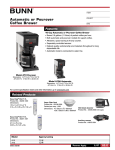
The CEH Industrial Unit Heater
OWNER’S GUIDE
Features & Benefits
• Commercial grade high temperature
manual reset
• High mass, tubular element for longer life
• Fan delay eliminates cold draft on startup and
disperses residual heat on shutdown
• Rugged die formed construction for durability
• Wire single or three phase to suit the application
• Vertical or horizontal delivery
• 5 Year Warranty
Tools Required:
Appropriate Fasteners
Crescent Wrench
Phillips Screwdriver
Straight Screwdriver
Strain Relief Connector
Wire Strippers
Models:
CEH-003M
CEH-003MB
CEH-003P
CEH-003PB
CEH-003RB
CEH-003R
CEH-003SB
CEH-005M
CEH-005MB
CEH-005P
CEH-005PB
CEH-005R
CEH-005SB
• Recommended for elevations under 7500 feet
IMPORTANT INSTRUCTIONS
WARNING
Turn the electrical power off at the electrical
panel board (circuit breaker or fuse box) and lock
or tag the panel board door to prevent someone from
turning on power while you are working on the
heater. Failure to do so could result in serious
electrical shock, burns, or possible death.
7.
WARNING
Overheating or fire may occur. DO NOT place the heater
behind doors.
8.
WARNING
Fire or explosion may occur. DO NOT place heater in any
area where combustible vapors, gases, liquids, or excessive
lint or dust are present.
9.
WARNING
Burn Hazard. This heater is hot when in use. To avoid burns,
do not let bare skin touch hot surfaces. Use extreme caution
when any heater is used by or near children or invalids.
10.
WARNING
Risk of Electrical Shock. Connect grounding lead to grounding terminal provided. Keep all foreign objects out of
heater.
11.
WARNING
Risk of Fire. Do not block heater. Heater must be kept clear
of all obstructions: maintain a 3 feet minimum clearance in
front, 12 inches on each side, and 6 inches from the rear.
Heater must be kept clean of lint, dirt and debris (See
Maintenance Instructions)
1. Read all instructions before using this heater.
2. Read all information labels. Verify that the electrical supply
wires are the same voltage as the heater.
3. All electrical work and materials must comply with the
National Electric Code (NEC), the Occupational Safety and
Health Act (OSHA), and all state and local codes.
4. If you need to install a new circuit or need additional wiring
information, consult a qualified electrician.
5. Protect electrical supply from kinks, sharp objects, oil,
grease, hot surfaces or chemicals.
6. Do not install heater below an electrical convenience
receptacle.
SAVE THESE INSTRUCTIONS
TEL: 360-693-2505 Fax: 360-694-8668 P.O. Box 1675 Vancouver, WA 98668-1675
READ ALL INSTRUCTIONS AND SAFETY
INFORMATION.
Installation Instructions
PLACEMENT: Install the CEH unit heater vertically or horizontally. Brackets are also available for ceiling mount
or wall mount applications.
THERMOSTAT: A line voltage OR low voltage thermostat is required for operation. A Cadet wall thermostat is
recommended for ultimate control and comfort.
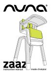
Horizontal Delivery
Heaters should be located so that the air streams
of the individual units "wipe" the exposed walls of
the building without blowing directly against the
wall. Recommended spacing between the units
is 12 feet. Locate heaters so their air streams are
not subjected to interference from columns,
partitions, machinery, etc.
(See Figure 1)
WARNING!
When working
with electricity,
turn the electrical
power off at the
electrical panel
board and lock or
tag the circuit
breaker door.
Failure to do so
could result in
serious electrical
shock, burns, or
possible death.
Figure 1.
CEILING
BACK
WALL
M
(1 IN
5. . 6
2 "
CM
1/2"
MOUNTING
BOLT
MIN. 6"
(15.2 CM)
OPTIONAL
MOUNTING
BRACKET
SID
WA E
LL
"
MIN. 10 s)
W Unit
(3.3–5 K M)
C
4
(25.
)
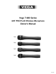
Figure 2. Horizontal mounting clearances with
optional bracket (CEK-M1).
MAXIMUM MOUNTING HEIGHT
(TO BOTTOM OF UNIT)
Failure to follow
warnings may
cause heater to
eject sparks, ignite
materials, or cause
electrical shock.
Mounting the CEH Unit Heater
CAUTION: THE CEILING OR WALL MOUNTING
STRUCTURE AND ANCHORING PROVISIONS
MUST BE OF SUFFICIENT STRENGTH TO
SUPPORT THE COMBINED WEIGHT OF THE
HEATER AND MOUNTING BRACKETS
.)
R (MIN
FLOO
6' TO .13 M)
(2
4 M)
8' (2.4 DA
NA
IN CA
WARNING!
Risk of Fire. Heaters
must be kept clean
of lint, dirt and
debris.
In an area where the air temperature will be maintained at less than 68˚F, the heater should be mounted in a postion that will not blow directly on people
working in the area.
A minimum clearance for each heater (both horizontal and vertical mount) is listed in Figure 2.
Please follow these recommendations to avoid
potential problems with the function and safety of the
heater.
MODEL
CEH-003
CEH-005
HORIZONTAL
DISCHARGE
9'
9'
VERTICAL
DISCHARGE
10'
10'
General Safety Information
The ceiling or wall on which the heater is to be
mounted must be of adequate strength to support the
heater. Plaster or suspended ceilings will not support this type of heater. For greater stability, we
recommend the use of threaded rods.
Do not mount the heater where volatile liquids or
gases will be present or where it will be exposed
to rain or mist. All combustible materials should
be kept at least 3 feet away from front of the heater.
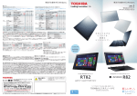
Horizontal Discharge
(See Figure 2 for minimum clearances)
1. Mounting with rod from ceiling or superstructure: (Figure 3)
a. Remove the four factory installed bolts from
the top of the unit and screw them into the
threaded holes in the back.
b. Install four 5/16-18 threaded rods in holes
and secure in place using lock (jam) nuts.
(Figure 3)
c. Attach the four mounting rods to the ceiling
or overhead structure and anchor securely.
2. Mounting with optional bolt-on ceiling
brackets: (Figure 2)
a. Bolt mounting bracket on top of unit using
the four factory installed bolts.
b. Suspend the unit from ceiling or overhead
structure using a 1/2 inch threaded rod or
bolt, allowing a minimum 6 inches clearance
from the ceiling. Using lock (jam) nut, anchor
securely.
3. Mounting with optional wall hanger arm and
mounting bracket: (See Parts List items #10 & #11)
a. Bolt mounting bracket on top of unit using
four factory installed bolts.
b. Attach the wall hanger arm to wall using
four 3/8 inch bolts or masonry fasteners.
c. Suspend the unit from hanger arm using
1/2 inch bolt. Place the rubber washer
provided between the mounting brackets.
5/16-18
Threaded
Mounting
Holes
C
A
D
FRONT
MOUNTING ROD DIMENSIONS
UNIT KW
ROD THREAD
3.3, 5.0
5/16-18
A
B
C
D
6" (15.2CM) 6.75" 4.04" 0.75"
Figure 3. Horizontal discharge rod spacing
2
B
Installation Instructions
Vertical Delivery
In buildings with high ceilings or bays, vertical
delivery unit heaters are recommended to produce
comfort in central areas. They are best used when
the perimeter heat loss is adequately controlled. In
combination with horizontally discharged units,
they aid in providing good air mixture (See Figure 4).
Vertical discharging units are mounted high above
machinery, assembly lines, etc.
In an application where only vertical discharging
units will be used, the air streams must overlap to
blanket outside walls and provide good heat distribution (See Figure 5).
Mounting the CEH Unit Heater
CAUTION: THE CEILING OR WALL
MOUNTING STRUCTURE AND ANCHORING
PROVISIONS MUST BE OF SUFFICIENT
STRENGTH TO SUPPORT THE COMBINED
WEIGHT OF THE HEATER AND MOUNTING
BRACKETS
Vertical Discharge
(See Figure 6 for minimum clearances)
1. Install four 5/16-18 threaded rods into the
threaded holes in the back of the heater and
secure in place using lock (jam) nuts (Figure 7).
2. Attach the four mounting rods to ceiling or overhead structure and anchor securely.
Figure 4.
Figure 5.
WARNING!
Risk of Electrical
Shock. Turn off all
power at the electrical panel board supplying power to the
heater before doing
any electrical
wiring.
NOTE: When mounting for vertical discharge,
position unit so that access door opens away
from nearest wall. This permits maximum
access to wiring compartment (Figures 2 & 6).
E
G
H
5/16-18
Threaded
Mounting
Holes
BACK
F
MOUNTING ROD DIMENSIONS
Figure 6. Ceiling mount. Vertical mounting clearances.
General Safety Information
The ceiling or wall on which the heater is to be
mounted must be of adequate strength to support
the heater. Plaster or suspended ceilings will not
support this type of heater. For greater stability, we
recommend the use of threaded rods.
Do not mount the heater where volatile liquids or
gases will be present or where it will be exposed to
rain or mist. All combustible materials should be
kept at least 3 feet away from front of the heater.
In an area where the air temperature will be maintained at less than 68˚F, the heater should be mounted in a position that will not blow directly on people
working in the area.
A minimum clearance for each heater (both horizontal and vertical mount) is listed in Figure 6.
Please follow these recommendations when
mounting to avoid potential problems with the function and safety of the heater.
UNIT KW ROD THREAD
3.3, 5.0
5/16-18
E
F
G
H
6" (15.2 CM) 9.63" (24.5 CM) 4.04" (10.3 CM) 2.10" (5.3 CM)
Figure 7. Vertical discharge rod spacing
Operation and Maintenance
How to operate your heater
Turn your built-in or wall thermostat to the desired
setting. The heater will run for approximately
twenty seconds before the fan comes on. The
heater will then run until the thermostat setting is
reached. Fan will continue to run with elements
shut off for approximately seventy seconds and
then will shut off. This cycle will continue as needed based on thermostat setting. Do not use breaker panel or fuse box to control heater. Be sure
power to heater is constant all the time.
Maintenance
1. Shut off circuit breaker to heater.
2. Remove front diffuser grill or 3 of the center
louvers in front of fan area.
3. Using a compressor, blow air through the outer
cabinet louvers and finned element areas.
(Do not touch sharp surfaces on elements).
While holding fan blade (to avoid damage or
bending) carefully blow inside the fan motor
area.
4. Carefully wipe off the fan blade without
damaging or bending it.
5. Reinstall front diffuser or air vanes.
6. Restore power to heater.
WARNING!
Overheating or fire
may occur. DO NOT
place the heater
behind doors.
3
Wiring Instructions
CAUTION: TO AVOID ELECTRICAL SHOCK, BE SURE ELECTRICITY IS TURNED OFF AT ELECTRICAL PANEL BOARD BEFORE WIRING.
ALL WIRING MUST BE DONE IN ACCORDANCE WITH LOCAL CODES AND THE HEATER MUST BE GROUNDED AS A PRECAUTION AGAINST
POSSIBLE ELECTRIC SHOCK. IN ABSENCE OF LOCAL CODES, FIELD WIRING TO THE UNIT SHALL COMPLY WITH CURRENT PROVISIONS OF THE AMERICAN NATIONAL ELECTRICAL CODE OR YOUR NATIONAL ELECTRICAL CODE, AS APPLICABLE.
NOTE: Connect heater only to a line with the voltage and frequency specified on the nameplate.
Branch Circuit Connections (Power)
1. Wiring compartment access door is hinged. To open, turn single screw on the side 1/4
turn (see Figure 8). Do not try to remove screw.
2. A knockout is provided in the back of the unit for field wiring (See Figure 8). This is a
multiple diameter knockout. Use the diameter that fits the required conduit size.
3. A ground terminal is provided near the junction block for field wiring. The ground
should be connected before any other connections.
4. The junction block is equipped with box terminals sized to accept the correct power
supply wire. Wire rated at 600 volts and 75˚C is satisfactory for branch circuit
connections. Either copper or aluminum conductors may be used. NOTE: the center
box terminal on the three pole junction block is used only for 3-phase operation.
5. Each heater has a wiring diagram on the inside of the access door. Consult this
diagram before making any field connections.
BACK
Hinge
Power
Wiring
Knockout
Access Door
Control
Wiring
Knockout
Figure 8.
Knockout locations
1/4 Turn Captive Fastener
CAUTION – READ THESE INSTRUCTIONS CAREFULLY WHEN USING ALUMINUM WIRING
1. Carefully strip insulation from aluminum conductors and coat ends of conductors with suitable corrosion inhibitor ("Pentrox A"
or equivalent).
2. Wire brush aluminum surface, removing corrosion; re-coat with corrosion inhibitor.
3. Connect aluminum wiring and tighten connection securely. CAUTION: Do not exceed pressure needed for making a typical copper
connection.
4. Coat entire connection with inhibitor.
5. All connections using aluminum conductors should be periodically re-checked for tightness.
6. NOTE: DO NOT JOIN ALUMINUM CONDUCTORS DIRECTLY TO COPPER.
DUAL RATED 240/208 VOLT MODELS: All 240 volt models may be
operated at 208 volts with a corresponding reduction in output. When
the heater is connected to a 208 volt power supply, disconnect the
transformer lead from the terminal marked 240V and connect it to the
terminal marked 208V. 277 volt units may only be used on single phase
circuits. 480 volt units may only be used on three phase circuits.
3-Phase Connections
Single or 3-phase power connections may be used on all 208 and
240/208 volt, 3.3–5 KW models. These units come factory wired for
single-phase power but may be wired for 3-phase power by reconnecting two wires. This is done as follows:
1. Models with Line Voltage Control (See Figures 9 & 10)
FRONT
Factory wired for
single phase
power (line
voltage control
models).
Orange
wire
a. Disconnect the orange wire from the junction block terminal
and connect it to the orange wire on the small terminal block and,
b. Disconnect the red wire from the junction block and connect it
to the terminal in the center of the block.
2. Models with 24 Volt Control (see Figures 11 & 12)
a. Disconnect the orange wire from the junction block
terminal and connect it to the orange wire on the contactor
terminal and,
b. Disconnect the red wire from the junction block and
connect it to the terminal in the center of the block.
FRONT
FRONT
Terminal
block
Orange
wire
Heater
elements
Factory wired for
single power
phase
3-phase
power
(24 volt
(line voltage
control models).
Red
wire
Orange
wire
Red
wire
Contactor
Factory wired for
3-phase
single power
phase
(line voltage
power
(24 volt
control models).
Orange
Orange
wire
wire
Red
wire
Junction block
block
Junction
for field
field wiring
wiring
for
Terminal
Terminal
block
block
Orange
Orange
wire
wire
BACK
FRONT
Factory wired for
3-phase power
(24 volt control
models).
Orange
wire
Terminal
block
Orange
wire
Heater
elements
Contactor
Red
wire
Junction block
for field wiring
Figure 12.
BACK
BACK
NOTE: Supply wires must feed direct from breaker to junction block. Thermostat wires connect to terminal board. See
wiring diagrams for your specific model.
Figure 10.
4
Figure 11.
Heater
Heater
elements
elements
Red
wire
Contactor
Red
wire
Junction block
for field wiring
BACK
FRONT
FRONT
Orange
wire
Heater
elements
Junction block
for field wiring
Figure 9.
Terminal
block
Wiring Instructions
Control Voltage Wiring
1. A knockout is also provided in the back of the unit for control wiring. This knockout is sized for 1/2" conduit. (see Figure 13)
2. Thermostat wire shall be as follows:
a. Line voltage control models: Use NEC Class 1, 600V, 90˚C, AWG #10 wire with copper conductor or same gauge wire as
supply line.
b. 24 volt control models (B package): Use NEC Class 1, 600V, 90˚C, AWG #18 wire with copper conductor.
Use H1 + P1, terminals for connection (Do not use jumpers).
3. Install wall thermostats in accordance with the installation instructions supplied with the thermostat.
NOTE: Do not locate thermostat in an area exposed to unusual temperature conditions or poor air circulation.
NOTE: a. Line voltage control models of 3.3KW and 5.0KW ratings that are 208 and 240 volt, wired for 3-phase operation, should not
be used with a wall thermostat. This applies to the following models:
CEH-003-M
CEH-003-P
CEH-005-M
CEH-005-P
These models come factory wired for single phase. When these models are converted in the field to 3-phase, DO NOT USE A WALL MOUNTED
THERMOSTAT. Thermostat control for 3-phase hookup should be provided by a CEK-TB2 (built-in thermostat).
b.When using model number CEH-005-M wired single phase (factory wired) use the following thermostats:
Wall Mount – C611-25,
Built-In – CEK-TB2 (two-stage thermostat)
4. Connect the thermostat wires to terminals H1 and P1 as shown in Figure 13. On 208 and 240 volt, single-phase
models with line voltage control, (Not B package models) install jumpers as shown in Figure 13.
BACK
FRONT
Figure 14.
Manual reset limit
Heater Elements
To Thermostat
H1 H2
P1 P2
Connect Thermostat
Wires To P1 and H1
F2
F1
Control Terminal Board
Line Voltage
Control Models
(Singe Phase):
Install jumpers
between H1 and H2
and P1 and P2 on
208/240V units
(note dashed lines).
A manual reset thermal limit is
factory installed on all models.
The limit is located on the front of
the heater. The manual reset limit
will not reset until the button is
pushed and heater has cooled
down. (208/240V line voltage control heaters use two manual reset
limits)
FRONT
Manual Reset Limit
Figure 13. Thermostat wiring connections
Wiring Diagrams
5
Wiring Diagrams
6
Wiring Diagrams
Parts List
1.
2.
3.
4.
402023
402045
402024
402046
402025
402049
402026
402027
402028
402048
402029
402030
001601
051408
051409
051414
050323
050326
050327
5.
6.
7.
8.
9.
10.
11.
12.
13.
14.
052403
052501
052502
052402
052401
052601
052603
09670
09660
410102
053304
050520
09610
09615
ELEMENT, CEH-003-M
ELEMENT, CEH-003MB
ELEMENT, CEH-003-P
ELEMENT, CEH-003-PB
ELEMENT, CEH-003-R
ELEMENT, CEH-003RB
ELEMENT, CEH-003-SB
ELEMENT, CEH-005-M
ELEMENT, CEH-005-P
ELEMENT, CEH-005-PB
ELEMENT, CEH-005-R
ELEMENT, CEH-005-SB
FAN BLADE, CEH-003 & CEH-005
FAN MOTOR, CEH-003-M, P & CEH-005-M, P
FAN MOTOR, CEH-003-R & CEH-005-R
FAN MOTOR, CEH-003-S & CEH-005-S
LIMIT, CEH-003, CEH-005, 208 & 240 VOLT
WITH LINE VOLTAGE CONTROL
LIMIT, CEH-005M, P
LIMIT, CEH-003-PB, MB, R & SB, CEH-005-PB,
MB, R & SB
TERMINAL BOARD
9
CONTACTOR, ALL UNITS WITH AN “S” SUFFIX
CONTACTOR, MB, PB (OPTIONAL 24 VOLT CONTROL)
JUNCTION BLOCK, CEH-003, CEH-005
TERMINAL BLOCK
TRANSFORMER, 240/208 VOLT
TRANSFORMER, 480 VOLT
CEK-WM, WALL MOUNTING ARM KIT (OPTIONAL)
CEK-M1, 3.3-5.5 KW HAT BRACKET (OPTIONAL)
AIR DIFFUSER, 3.3 - 5.0 KW
FAN DELAY RELAY - 24 VOLT
FAN DELAY RELAY - 240 VOLT
CEK-TB1, SINGLE POLE INTEGRAL THERMOSTAT (OPTIONAL)
CEK-TB2, TWO STAGE INTEGRAL THERMOSTAT (OPTIONAL)
10
11
1
12
3
2
4
14
13
6
7
5
8
IMPORTANT: When ordering replacement parts, specify the heater "Model Number" and "Product Date Code" shown on unit rating plate or label found inside access door. Select appropriate "Part No." from this sheet for each part requested. Consult your local
distributor or call Cadet at 360.693.2505. Specifications or designs are subject to change or discontinuance without notice or without incurring obligation.
7
Troubleshooting Chart
CONSULT LOCAL ELECTRICAL CODES TO DETERMINE WHAT WORK MUST BE PERFORMED BY QUALIFIED ELECTRICAL SERVICE PERSONNEL
Symptom
Heater does not operate.
Element heats, fan does not
operate.
Fan operates, but does not discharge warm air.
Heater does not shut off.
Heater discharges smoke.
Fan blades do not turn.
Manual reset limit trips
repeatedly.
Problem
Solution
1. Voltage not correct for application.
2. In line thermostat used.
1. Check voltage with voltmeter and/or consult an electrician.
2. Thermostat wires to terminal board; supply wires to junction block (see
wiring diagram).
3. Remove obstruction. Push manual reset in front.
4. Turn knob past sound of click.
5. Turn circuit breaker on.
6. Replace manual reset.
1. Replace the delay switch.
2. Replace motor and/or check wire connection.
3. Adjust blade as needed.
1. Allow heater to cool, then push reset button.
2. Check with ohmmeter and replace if needed.
3. Check and correct loose wire.
1. Close doors or windows. (See “Operation & Maintenance” section for
instructions).
2. Replace thermostat.
1. Clean heater. (See “Operation & Maintenance” section for instruction).
3. Heater is or has been blocked.
4. Thermostat set too low.
5. Circuit breaker is off.
6. Defective manual reset.
1. Defective time delay switch.
2. Bad motor or wire connection.
3. Fan hitting or rubbing.
1. Manual reset limit tripped.
2. Defective heater elements.
3. Wire loose from elements.
1. Heat loss from area is greater than
heater capacity.
2. Defective thermostat.
1. Dust, dirt and lint accumulated
inside the heater.
2. Jammed fan blades.
1. Manual reset limit tripped.
2. Jammed fan blades.
3. Defective motor.
1. Overheating.
2. Overheating at shutdown.
3. Overheating from excessive dust,
dirt or lint particles.
4. Overheating due to location elevation.
5. Power interruptions.
2. Remove obstruction.
1. Remove obstruction. Once heater has cooled, push reset button.
2. Remove obstruction.
3. Replace fan motor.
1. Check all clearance requirements.
2. Discontinue use of breaker to control heater, or replace time delay switch.
3. Clean heater. (See "Operation and Maintenance" section for instructions)
4. Location elevation exceeds recommended 7500 feet.
5. Power to heater needs to be constant.
Warranty
Warranty Information
Maintenance: For safer operation and to prolong the life of the heater, it is necessary to follow the maintenance instructions included with each
heater. Failure to properly maintain the heater will result in the warranty being voided. All warranties offered to original consumer only. Warranty
instructions included with each heater.
All Cadet Products
LIMITED ONE-YEAR WARRANTY: LIMITED ONE-YEAR WARRANTY: Cadet Manufacturing Co. will repair or replace any Cadet product, including thermostats, found to be defective or malfunctioning from first date of purchase through the first year.
Extended Product Warranties
Model CEH
LIMITED FIVE-YEAR WARRANTY: Cadet Manufacturing Co. will repair or replace any Cadet Unit Heater (CEH) element or motor found to be defective
or malfunctioning from first date of purchase through the fifth year.
THESE WARRANTIES DO NOT APPLY:
1. To conditions resulting from improper installation or incorrect supply voltage;
2. To conditions resulting from improper maintenance, misuse, abuse, accident, or alteration;
3. To service calls, or any warranty labor not performed at the Cadet Manufacturing facility;
4. If the date of manufacture cannot be determined;
5. To freight damaged products.
CADET SHALL NOT BE LIABLE FOR DAMAGES SUCH AS PROPERTY DAMAGE AND/OR INCIDENTAL EXPENSES RESULTING FROM BREACH OF THESE
WRITTEN WARRANTIES OR ANY IMPLIED WARRANTY.
These warranties give you specific legal rights, and you may also have other rights which vary from state to state. Cadet neither assumes, nor
authorizes anyone to assume for it, any other obligation or liability in connection with these electric heaters or any part of such heaters.
If the product should become defective during the warranty period, contact Cadet Manufacturing Co. at 360-693-2505 for instructions on how to have
the repair or replacement processed. Products returned without authorization will be refused.
Parts and Service
Contact Cadet for information on parts or service.
©2006 Cadet Manufacturing Co.
8
Printed in U.S.A. Rev. 11/06 #720019