1
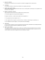
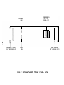
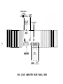
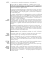
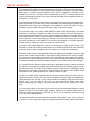
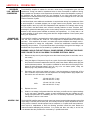
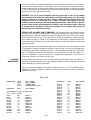
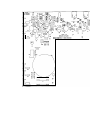
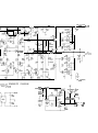
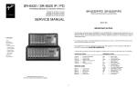
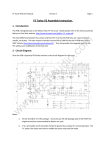
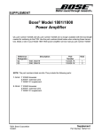
Series 9180/ 9270 Power Amplifier
NOTICE - IMPORTANT SAFETY INFORMATION
The lightning flash with arrowhead symbol within
an equilateral triangle is intended to alert the
user to the presence of uninsulated “dangerous
voltage” within the products enclosure, that may
be of sufficient magnitude to constitute a risk of
electric shock to persons.
WARNING: TO PREVENT FIRE OR
SHOCK HAZARD, DO NOT EXPOSE THIS
EQUIPMENT TO RAIN OR MOISTURE.
The exclamation point within an equilateral
triangle is intended to alert the user of the
presence of important operating and maintenance (servicing) instructions in the literature
accompanying the appliance.
1.
READ INSTRUCTIONS
All the safety and operating instructions of your Hafler equipment should be read before power is applied to the
equipment.
2.
RETAIN OWNERS MANUAL
These safety and operating instructions should be retained for future reference.
3.
HEED WARNINGS
All warnings on the equipment and in the operating instructions are important and should be followed.
4.
FOLLOW INSTRUCTIONS
All operating and use instructions are important and should be followed.
5.
HEAT
The equipment should be kept away from areas of high temperature, such as heater vents, radiators, stoves/ovens,
fireplaces, etc.
6.
VENTILATION
The equipment should be used in an area suitable for proper ventilation. Care should be taken not to impede airflow
in and around the cabinet. Do not mount on a carpeted shelf or in a sealed enclosure. Allow for proper clearance
above the equipment.
7.
WATER AND MOISTURE
The equipment should not be used in or around water, such as a bathtub, sink, or swimming area. Also, the equipment
should not be used in areas prone to flooding, such as a basement.
a.
9.
POWER SOURCES
The equipment should be connected only to a power source of the same voltage and frequency as that listed on the
rear panel above the power cord entry point.
POWER CORD PROTECTION
Power cords should be arranged so that they do not interfere with the movement of objects in the room: people, fan
blades, utility carts, etc. Also, care should be taken that the cord is not pinched or cut, and placed so that it is not
in danger of being pinched or cut, as in under a rug, around a tight corner, etc.
10. POWER CORD GROUNDING
The power supply cord is of a three wire grounded type, designed to reduce the risk of electric shock sustained from
a live cabinet. It is assumed to be of suitable length for most uses of the equipment. The use of extension cords and
power strips is discouraged unless they are of suitable rating to deliver the required total current for safe operation
of all connected equipment. Furthermore, extension cords or power strips must provide the same three wire
grounded connection. It is important that the blades of the equipment’s plug be able to fully insert into the mating
receptacle. Never remove the round grounding pin on the plug in an attempt to mate to a two wire ungrounded
receptacle: use a grounding adaptor with the grounding tab or wire suitably connected to earth ground.
-1-
11. NON-USE PERIODS
During periods of extended non-use, the power cord should be unplugged from the power source.
12.
CLEANING
The equipment should be cleaned only as detailed in the operating instructions.
13.
OBJECT AND LIQUID ENTRY
Care should be taken so that objects and/or liquids, such as cleaning fluids or beverages, are not spilled into the
enclosure of the equipment.
14. DAMAGE REQUIRING SERVICE
Hafler equipment should be serviced by qualified service personnel when:
A. The power supply cord or plug has been damaged, or
B. Objects have fallen, or liquid has been spilled into the equipment, or
C. The equipment has been exposed to rain, or
D. The equipment does not appear to operate normally or exhibits a marked change in performance, or
E. The equipment has been dropped, or the enclosure has been damaged.
15.
SERVICING
The user should not attempt to service the equipment beyond that which is described in the operating instructions.
All other service should be referred to qualified service personnel.
16. CARTS AND STANDS
The equipment should be used with carts or stands only of sufficient strength and stability for the use intended.
An equipment and cart combination should be moved with care. Quick stops and starts, excessive force, and
uneven surfaces may cause the equipment and cart combination to topple.
-2-
TABLE OF CONTENTS
PERFORMANCE SPECIFICATIONS ..........................................................................................
General Information ..............................................................................................................
INSTALLATION
Rackmounting.. ......................................................................................................................
4
4
Line Voltage.. .........................................................................................................................
5
5
5
OPERATION/CONNECTIONS
Power Cord Connection/Power Switch.. ...............................................................................
5
Ventilation/Placement.. .........................................................................................................
Inputs .....................................................................................................................................
5
Front Panel View Diagram.. ..................................................................................................
6
7
Rear Panel View Diagram ....................................................................................................
Outputs ..................................................................................................................................
8
Gain Controls.. ......................................................................................................................
Mono/Stereo Switching.. .......................................................................................................
8
Soft Turn-On System ............................................................................................................
8
Thermal Protection System ..................................................................................................
8
CIRCUIT HIGHLIGHTS ...............................................................................................................
ADDITIONAL INFORMATION
Loudspeaker Load Impedance Considerations ...................................................................
8
9
10
Adjusting Bias ......................................................................................................................
10
10
General Troubleshooting Hints ............................................................................................
11
Ground Loops ......................................................................................................................
11
Cleaning/Maintenance ........................................................................................................
12
Parts List.. ............................................................................................................................
Functional Block Diagram.. .................................................................................................
12
Changing Line Voltage Rating .............................................................................................
Component Layout Diagram.. .............................................................................................
Circuit Schematic Diagram .................................................................................................
SERVICE POLICY AND LIMITED WARRANTY.. .....................................................................
-3-
14
15
17
19
PERFORMANCE
SPECIFICATIONS
All specifications are for 20 Hz - 20 kHz, at full power into 8 ohms, unless specified otherwise.
GENERAL
INFORMATION
Power Rating: 9180:
105 watts per channel (8 ohms)
150 watts per channel (4 ohms)
300 watts mono (8 ohms)
9270:
135 watts per channel (8 ohms)
200 watts per channel (4 ohms)
400 watts mono (8 ohms)
Rated THD:
less than 0.025%, typically 0.005% at 1 kHz
Full Power Bandwidth:
0.3 Hz to 116 kHz
Signal to Noise Ratio:
greater than 100 dB, unweighted
Input Impedance:
47,000 ohms
Input Sensitivity: 9180:
9270:
1.4 volts RMS
1.6 volts RMS
Damping Factor:
300 to 1 kHz, 200 to 10 kHz
Slew Rate:
50 V/uS
Controls:
Power Switch, Left/Right Gain Controls, Mono/Stereo Switch
Inputs:
Right and Left/Mono RCA jacks
outputs:
Right, Left, and Mono 5-Way Binding Posts
Power Consumption:
100 watts quiescent, 1200 watts maximum
Size:
17”(W) x 12.5”(D) w3.5”(H) excluding feet, faceplate 17” or 19”(W)
43.2cm(W) x 31.7cm(D) x 8.9cm(H)
faceplate 43.2cm or 48.3cm(W)
Weight:
9180:
9270:
33 Ibs., 15 kg, net.
35 Ibs., 15.9 kg, net.
-4-
excluding feet,
INSTALLATION
RACKMOUNTING
VENTILATION/
PLACEMENT
The 9180/9270 Amplifier is supplied in either a 17” Black Version, or a 19” Silver Version. The 19”
model has rackmounting holes provided for installation in equipment racks. The holes are on standard
EIA spacings. Due to conflict with adjacent equipment, it may be advisable to remove the four rubber
feet from the bottom of the unit. The feet may be removed from the outside, with no dis-assembly of
the chassis necessary.
The 9180/9270 Amplifier can produce considerable heat during normal operation. The amplifier should
be placed on a hard, smooth surface to allow air to circulate beneath the unit. Additionally, allow at least
one inch of free space on either side, and several inches above and behind the amplifier to allow air
circulation around the heatsinks. This is particularly important when the unit is installed in a closed
cabinet.
In applications where the amplifier is driving low impedance and/or low efficiency loudspeakers at high
levels, thermal shutdown may occur if inadequate ventilation is provided. If this occurs, it may be
necessary to move the amplifier to a location with better free air circulation.
The amplifier should be located at least several inches away from sensitive components, (such as
preamplifiers, tuners, CD players, turntables, etc.) due to the possibility of audible hum or buzz from
magnetic radiation.
LINE
VOLTAGE
The 9180/9270 Amplifier is configurable for either 100, 120, 220 or 240 volt operation. This is
accomplished by moving the Voltage Selector on the printed circuit board. The procedure is detailed
in the section “CHANGING LINE VOLTAGE RATING”.
Make sure that the unit is configured for your local AC line voltage before attempted use. The
configuration is labelled directly above the power cord connector.
OPERATION/CONNECTIONS
POWER CORD
CONNECTION/
POWER SWITCH
Units wired for 100, 220 and 240 VAC are supplied without power cords. Local agents will supply cords
with male connectors appropriate to the local standard.
Units wired for 120 VAC are supplied with a detachable AC power cord. The female connector plugs
into the receptacle provided on the rear panel. This power cord is a standard IEC Type
Type320,
320,3-wire,
3-wire,
16 gauge assembly. Should replacement ever be necessary, be sure to replace it with an identical cord.
Never remove the grounding pin from the male end of the cord. In applications where a grounded outlet
is not available, a ground adaptor should be employed, with the ground tab or wire of the adaptor
connected to a suitable earth ground.
The AC power cord of the amplifier must be connected to a receptacle capable of delivering a minimum
of 1200 watts. The convenience outlets of some preamplifiers are not rated for this power level. Before
connecting the amplifier, be sure to check the rating of such outlets, and take into account the power
consumption of any other connected components to determine the total maximum power consumption.
If the amplifier is connected to a component with a switched convenience outlet, then the amplifier’s
Power Switch may be left ON at all times, and the power controlled by the switched outlet. If the amplifier
is connected to an unswitched outlet, then the amplifier’s power should be controlled by the front panel
Power Switch.
INPUTS
All input connections to the amplifier must be performed with the amplifier off!
The left and right audio inputs to the amplifier are via standard RCA jacks. In addition to the printed
labelling above the jacks, the channels are identified by RED for right channel, and WHITE for left
channel. Connect these jacks to the output of the preamplifier or other signal source.
When operating the amplifier in the Mono Mode, only the left channel input should be used.
-5-
LEFT/MONO
GAIN
RACKMOUNT HOLES
(19” VERSION ONLY)
POWER SWITCH
UP - ON
DOWN - OFF
RIGHT
GAIN
9180 / 9270 AMPLIFIER FRONT PANEL VIEW
RACK HANDLES
(19” VERSION ONLY)
MONO/STEREO
SWITCH
RI Gt iT
IN - MONO
O U T - S T E R E O I N IT
AC LINE
VOLTAGE
RATING
LEFT/MONO
INPUT
-
II
- TT LINECORD
CONNECTOR
I!I
MONO+
OUTPUT
+
-
RIGHT
LEFT
OUTPUT OUTPUT
9180 / 9270 AMPLIFIER REAR PANEL VIEW
OUTPUTS
All output connections to the amplifier must be performed with the amplifier off!
I
3/4"3/4”
spacing,
The left and right audio outputs from the amplifier are via standard 5-way
5-waytype,
type,
spacing,
binding posts. Connect these binding posts to the loudspeakers. The amplifier’s binding posts will
accept single or dual banana plugs, spade lugs, pin plugs, or bare wires. If using bare wires, it is
recommended that the ends of the wire be tinned with solder so that no stray strands can cause
a short circuit to the chassis or adjacent terminals.
To ensure proper speaker phasing and frequency response, be sure to connect each respective
amplifier RED (+) terminal to the speaker RED (+) terminal, and the amplifier BLACK (-) terminal
to the speaker BLACK (-) terminal. The polarity symbols (+/-) for Stereo Mode are labelled below
the amplifier’s binding posts.
For operation in the Mono Mode, a single loudspeaker should be connected to the two RED binding
posts only. No connection is made to the amplifier’s BLACK binding posts. Connect the speaker’s
RED (+) terminal to the amplifier’s RED terminal labelled (+), and the speaker’s BLACK (-) terminal
to the amplifier’s RED terminal labelled (-). The polarity symbols (+/-) for the Mono Mode are
labelled above the amplifier’s binding posts.
GAIN
CONTROLS
The 9180/9270 Amplifier is equipped with front panel mounted Gain Controls. These controls may
be used to attenuate the input signal to the amplifier. The maximum clockwise position of these
controls applies the full input signal to the amplifier. Intermediate positions of these controls will
partially attenuate the signal, and the full counter-clockwise position attenuates the input signal
completely.
Most applications will dictate that these controls be set to their maximum clockwise position. In
situations of unusually high level signal sources, or for matching levels in multiple amplifier
installations, it may be desirable to use an intermediate position of the Gain Controls. Unless
intentionally introducing different gain levels in the two channels of the amplifier, these controls
should normally be set at the same rotational position.
In the Mono Mode, the Left Gain Control effects the overall gain of the amplifier. The Right Gain
Control has no effect.
MONO/
STEREO
SWITCHING
The 9180/9270 Amplifier may be operated in the normal two channel Stereo Mode, or may be
converted (bridged) to a higher power, single channel amplifier in the Mono Mode.
Operation of the Stereo/Mono switch must be performed with the amplifier off! Set the Stereo/
Mono Switch in the OUT position for Stereo Mode, or in the IN position for Mono Mode. Mono Mode
operation requires different input and output connections: consult the sections of the manual titled
“Inputs” and “Outputs”.
SOFT TURNON/OFF
SYSTEM
The 9180/9270 Amplifier is equipped with a Soft Turn-On/Off System that gradually activates the
amplifier’s circuitry to avoid spurious noises as the power supply stabilizes.
At turn-off, this same system rapidly deactivates the amplifier’s circuitry before the power supply
begins to collapse, again eliminating any spurious noises.
THERMAL
PROTECTION
SYSTEM
The 9180/9270 Amplifier is equipped with a Thermal Protection System that constantly monitors
the temperature of the heatsinks. When the heatsink temperature reaches a pre-determined level,
the amplifier’s circuitry is electronically shut down through the same system that provides the Soft
Turn-On function. When the heatsinks cool to a safe operating temperature, normal operation of
the amplifier resumes.
-8-
CIRCUIT HIGHLIGHTS
The input stage of the 9180/9270 Amplifier utilizes four low-noise, High-g, JFET’s (high transconductance
junction field-effect transistors), in a fully complimentary, symmetric configuration. This circuit configuration results in excellent front-end headroom and a simple, straightforward connection to the
remainder of the circuitry. The ultra low noise characteristics of the JFET’s virtually eliminates noise
“mixing” (intermodulation) with the music signal, reducing discordant product frequencies known as
“noise grain”, or “noise fuzz”.
The input stage is cascode connected to convert the low voltage input system to the high voltage output
system, and “speeds up” the front end for superior bandwidth. The cascode stage is connected to an
emitter-follower and current mirror configuration that amplifies the current level about ten times,
necessary to drive the biasing string and final output stage driver emitter followers.
The final output stage uses multiple lateral MOSFET’s (Metal Oxide Semiconductor Field Effect
Transistors): four devices per channel in the 9180, and six per channel in the 9270. These devices,
unlike conventional bipolar transistors, have a negativetemperature coefficient, which means that they
do not exhibit “thermal runaway”. Thermal runaway is a phenomenon whereby a transistor heats up
as it conducts more current, which causes it to get hotter, and conduct more current, and so on, until
the device self destructs. Since MOSFET’s are inherently self-protecting, no sonically degrading,
complex circuitry is required to monitor and protect the output devices.
Furthermore, these lateral MOSFET’s exhibit a very linear input to output transfer function. Their
connection in circuits and operating characteristics are very similar to vacuum tubes, which is perhaps
responsible for their widely recognized sonic trait of being very “musical” and non-fatiguing.
Conversion to Mono Mode is accomplished by driving the negative input (feedback point) of the right
channel with the output of the left channel. This causes the right channel to mirror exactly the output
of the left channel, but 180 degrees out of phase. This creates twice the voltage swing to be available
across the two red output binding posts. This simple method of bridging the amplifier (involving only
one resistor) eliminates the costly and sonically degrading invertor circuitry used in other amplifiers.
The Thermal Protection System consists of thermistors (temperature sensitive resistors) mounted to
the heatsinks, connected to a comparator system that activates when the heatsinks reach an unsafe
operating temperature. The output of the comparator system is connected to a small MOSFET switch
that turns off the input stage of the amplifier, which effectively shuts down the entire amplifier. When
the heatsinks cool to a safe temperature, the amplifier is turned on again.
The Soft Turn On/Off System cooperates with the Thermal Protection System by sensing the high
voltage power supply. At power up, when both the comparator and power supply have stabilized to
normal operating levels, the Soft Turn On System activates the amplifier circuitry through the same
MOSFET switch in the input stage. At power down, the system deactivates the amplifier rapidly before
the power supply begins to collapse. This system eliminates spurious noises during the turn on/off
cycle.
The power supply utilizes a very large UI type transformer with dual multi-tapped primaries to allow
alternate connections for world-wide voltage operation. Selection of the various voltage options is
made via a simple multi-position plug inside the unit. The UI type of transformer construction results
in very low stray magnetic leakage.
The transformer feeds a conventional split full-wave bridge rectifier system. Power supply capacitance
is 15,000 uF per rail. Further power supply de-coupling is provided for the input stage of each channel.
-9-
ADDITIONAL INFORMATION
LOUDSPEAKER
LOAD IMPEDANCE
CONSIDERATIONS
The 9180/9270 Amplifier is suitable for use with a wide variety of loudspeaker types and load
impedances. Though not rated for impedances below 4 ohms, the amplifier is capable of driving
lower impedances. Operation at low impedances is limited by the thermal dissipation capacity of
the heatsinks and the airflow around the unit. Operation at very high power levels into low
impedances for extended periods may overheat the amplifier, but no damage will occur due to the
Thermal Protection System.
In the Mono Mode, some additional consideration is required when driving low impedances. When
a stereo amplifier is converted (bridged) into a single channel mono amplifier, each half of the
bridged amplifier “sees” only half of the loudspeaker’s load impedance. For example, when driving
an 8 ohm load in the Mono Mode, each channel is actually loaded to 4 ohms. Therefore, little
advantage is gained when attempting to drive 4 ohm loads (2 ohms per channel) in the Mono Mode,
because of the reduced power available at extremely low impedances. It is usually better to use
a stereo amplifier of higher power rating (rather than two bridged amplifiers of lower power) when
driving low impedances.
CHANGING LINE
VOLTAGE RATING
The 9180/9270 Amplifier is equipped with a simple means to adjust the AC line voltage rating for
100, 120, 220, or 240 volts AC, 50/60 Hz. The configuration is labelled above the power cord
connector. If the amplifier will be used in a location that requires a different line voltage, use the
following procedure to change the configuration. Review the modification instructions before
attempting this procedure. If any doubts exist about one’s ability to change the line voltage, it is
advisable that the procedure be conducted by a qualified technician.
WARNING! UNPLUG THE UNIT FROM AC POWER BEFORE ATTEMPTING THIS PROCEDURE. FAILURE TO DO SO CAN RESULT IN SEVERE ELECTRICAL SHOCK.
ADJUSTlNG BIAS
1)
Remove the top cover by removing the seven allen head screws (three on each side, one at
rear center).
2)
Using the diagram “Component Layout” as a guide, find the white Voltage Selector plug on
the printed circuit board located behind the front panel Power Switch. Note that this plug has
several alternate positions. Each position is labelled for where the end of the plug is to be
aligned for each appropriate voltage. Move this plug to the new desired position, making sure
that the plug is fully seated on the mating pins.
3)
Depending upon which new voltage is chosen, it may be necessary to change the AC line
fuse. Locate the clip-mounted Line Fuse adjacent to the Voltage Selector plug. Replace the
slow-blow fuse
fuse with a new slow-blow
fuse as follows:
9180:
100 and 120 VAC: 7 amp
220 and 240 VAC: 4 amp
9270:
100 and 120 VAC: 10 amp
220 and 240 VAC: 5 amp
4)
Replace the cover.
5)
Obtain a new voltage configuration label from the factory, and affix over the original markings
on the rear panel. Alternately, prepare a small self-adhesive label and indicate the new
voltage with permanent ink. Relabelling the unit is a vital safety requirement, particularly if
the amplifier is sold to a new owner.
The 9180/9270 Amplifier employs a single control per channel to set the bias operating point of the
output stage. This bias point is factory set, and normally should not require adjustment for the life
of the product. However, should improper bias be suspected, or if repairs have been made that
would require a readjustment of bias, the following procedure should be used. Review the
instructions before attempting this procedure. If any doubts exist about one’s ability to set the bias,
it is advisable that the procedure be conducted by a qualified technician.
-10-
WARNING! UNPLUG THE UNIT FROM AC POWER BEFORE ATTEMPTING THIS PROCEDURE.
FAILURE TO DO SO CAN RESULT IN SEVERE ELECTRICAL SHOCK.
REQUIRED TEST EQUIPMENT: Milliammeter capable of measuring at least 300 mA.
1)
Remove the top cover by removing the seven allen head screws (three on each side, one at rear
center).
2)
Using the diagram “Component Layout” as a guide, find the fuses labelled F1 and F2 for the left
channel, or F1 01 and F102 for the right channel.
3)
Working on one channel at a time, remove either one (and only one) of the fuses. Connect the
milliammeter to the two fuse clips, and set the meter to a scale capable of measuring at least 300
mA.
WARNING! THE NEXT STEP OF THIS PROCEDURE CAN EXPOSE THE OPERATOR TO
UNINSULATED HIGH VOLTAGES. KEEP ALL BODY PARTS CLEAR OF THE INTERNAL
CIRCUITRY OF THE AMPLIFIER.
4)
Apply power to the amplifier, and allow the unit to thermally stabilize for about three minutes. (If
using an analog meter, and the meter reads backwards, temporarily remove power and reverse
the meter leads.)
5)
Again referring to the diagram, locate the trimmer potentiometer labelled Pl for the left channel,
or P101 for the right channel. Using a small screwdriver, adjust the trimmer for a measured
current according to the following:
9180: 200 mA
9270: 300 mA
GENERAL
TROUBLESHOOTING
HINTS
6)
Remove power from the amplifier. Wait about one minute for the power supply to discharge, and
remove the meter connections. Replace the fuse.
7)
Repeat steps #2,3, 4, 5 and 6 for the other channel.
8)
Replace the covers.
The 9180/9270 Amplifier contains five internal fuses: one for AC line power, and four for DC power
supplies. These fuses should not generally blow unless a malfunction has occurred. These fuses
should be replaced only by a qualified technician, and only with the exact type(s) and rating of fuse(s)
originally supplied. If a fuse is replaced and blows again within a short time, check all output
connections for short circuits, or abnormally low speaker load impedances. If all connections and load
conditions appear to be correct, disconnect all power immediately and return for service.
If all controls, fuses, cables, etc. seem to be functioning properly, a process of one-at-a-time component
substitution should be employed until the defective unit is identified. If only one channel is not
functioning properly, a one-at-a-time reversal of interconnect and speaker cables from left to right
should reveal the malfunctioning component.
GROUND
LOOPS
Ground loops are characterized by a low level hum or buzz in the system. Loops are caused by a
voltage potential difference between two points in a ground circuit, and aggravated when multiple paths
for a given circuit exist. Noise-free audio performance is dependent upon all grounds being at the same
potential, with a single path for each ground connection. Ground loops can exist in two forms: 1) loops
created in audio interconnects, and 2) loops created between earth grounded chassis.
Mounting components to a rack with metallic rails may introduce ground loops between associated
equipment, because the rails can introduce a second ground path. The extent of this problem will
depend on the grounding arrangements of associated equipment. Ground loops can occur in nonrackmounted equipment, though it is less common.
If ground loops occur, and any other component in the system has a three wire grounded power cord,
the first step should be to use a ground adaptor (with the ground tab or wire of the adaptor not
connected) on the power cord plug of the preamplifier. DO NOT cut off the grounding pin on the plug!
-11-
It may be necessary to use additional adaptors on other grounded components if more than two
components are earth grounded. (In other words, only one earth ground per system should exist.)
Another potential source of multiple earth grounds is from coaxial antenna or cable service feeds
for FM or video sources, which usually are (and should be) earth grounded. The ground adaptor(s)
should cure this grounding problem as well.
WARNING: The use of ground adaptors (with the ground tab or wire of the adaptor
disconnected) will eliminate the safety feature of the grounded power cord. This safety
feature is intended to reduce the risk of electric shock should an internal fault in the
equipment result in an electrically “live” chassis. Therefore, this method of ground
isolation should be employed only when absolutely necessary, rather than as a general
practice. When using a ground adaptor for isolation, make sure that the power cord plug
is inserted into the receptacle in the same orientation as if no adaptor were present, to
maintain the same hot/neutral polarity.
SPECIAL NOTE ON VIDEO CABLE “GROUNDS”: As mentioned above, the ground conductor
of cable service and antenna feeds should be connected to earth ground. Often, however, due to
long feed lengths, especially in apartment distribution systems, this ground will be of poor quality
and could be a source of noise. This interference is usually characterized by a high frequency
noise, rather than a hum or a buzz. If such interference is experienced, a separate earth ground
connection should be made from the cable outlet nearest the audio/video equipment to a known
good earth ground.
If ground loops exist due to potential differences in the interconnects in rack mounted systems, then
it is advisable to isolate the preamplifier chassis from the rack rails. This may be accomplished by
sandwiching a thin sheet of insulating material (i.e., plastic washers or several layers of electrical
tape, etc.) between the rack and the preamplifier, and securing the unit with non-metallic (i.e.,
nylon, etc.) hardware. It may be necessary to insulate other components so that only one
component is directly connected to the rack rails.
CLEANING/
MAINTENANCE
If the faceplate should become soiled, it may be cleaned with a slightly damp, soft cloth and, if
necessary, a mild detergent. Do not use any abrasive cleaners or solvents. Unplug the power cord
before attempting any cleaning operations.
Except as specifically detailed in the owners manual, there are no user serviceable parts or
adjustments inside the 9180/9270 Amplifier, and all servicing should be referred to qualified,
authorized personnel.
PARTS
Parts ListLIST
DESIGNATORS
DESIGNATOR
l- 99:
101-l 99:
201-299:
301-399:
LEFT CHANNEL
RIGHT CHANNEL
COMMON PARTS
CHASSIS/POWER SUPPLY
VALUE
PART NUMBER
ALL RESISTORS 114 WATT, 1% METAL FILM
(unless
specified
otherwise))
R1,R101
R2,R102
R3,R103
R4,R104
R5,R105
R6,R106
R7,R107
R8,R108
R9,R109
R10,R110
R11,R111
R12,R112
2.43K
2.43K
47.5
47.5
66.1
47.5
47.5
1K
1K
6.61K
47.5K
2.43K
RMP/4-2431
RMP/4-2431
RMP/4-0475
RMP/4-0475
RMP/4-0681
RMP/4-0475
RMP/4-0475
RMP/4-1001
RMPN-1001
RMP/4-6811
RMP/4-4752
RMP/4-2431
-12-
DESIGNATOR
VALUE
PART NUMBER
R13,R113
R14,R114
R15,R115
R16,R116
R17,R117
R18,R118
R19,R119
R20,R120
R21 ,R121
R22,R122
R23,R123
R24,R124
R25,R125
R26,R126
R27,R127
R28,R128
R29,R129
R30,R130
R31 ,R131
R32,R132
267
267
1K
1K
100
100
47.5K
562
475
10
47.5
47.5
221
475
475
475
221
221
221
475K
RMP/4-2670
RMP/4-2670
RMP/4-1001
RMP/4-1001
RMP/4-1000
RMP/4-1000
RMP/4-4752
RMP/4-5620
RMP/4-4750
RMP/4-0100
RMP/4-0475
RMP/4-0475
RMP/4-2210
RMP/4-4750
RMP/4-4750
RMP/4-4750
RMP/4-2210
RMP/4-2210
RMP/4-2210
RMP/4-4753
DESIGNATOR
VALUE
PART NUMBER
DESIGNATOR
VALUE
PART NUMBER
R33,R133
R34,R134
R35,R135
R36,R136
R37,R137
R38,R138
R39,R139
R40,R140
R41,R141
R42,R142
R43,R143
R44,R144
R45,R145
R46,R146
R47,R147
R201
R202
R203
R204
R205
R206
R207
R208
R209
R210
R211
R212
R213
47.5K
33.2K
47.5K
100
100
100
100
15K
10,5W, Wirewound
1K
4.75M
1M
1M
1M
1M
7.5K, .5 W, Carbon
7.5K, .5 W, Carbon
100K
10K
18.2K
332K
18.2K
332K
1K
68.1K
33.2K
33.2K
47.5K
RMP/4-4752
RMP/4-3322
RMP/4-4752
RMP/4-1000
RMP/4-1000
RMP/4-1000
RMP/4-1001
RMP/4-1502
RW5-100
RMP/4-1001
RMP/4-4754
RMP/4-1004
RMP/4-1004
RMP/4-1004
RMP/4-1004
RC/2-752
RC/2-752
RMP/4-1003
RMP/4-1002
RMP/4-1822
RMP/4-3323
RMP/4-1822
RMP/4-3323
RMP/4-1001
RMP/4-6811
RMP/4-3322
RMP/4-3322
RMP/4-4752
C21,C121
C22,C122
C201
C301
C302
C303
C304
0.01,
Polypropylene
0.01,
Polypropylene
0.01, Polycarbonate
15000, Electrolytic
15000, Electrolytic
0.01, Ceramic
0.01, UL Approved
CPP-103A
CPP-103A
CYV-103
CER-159ES
CER-159ES
CD-l 03/20
CD-103A
VR1 ,VR101
50K
RVH-503G
Q1 ,Q101
Q2,Q102
Q3,Q103
Q4,Q104
Q5,Q105
Q6,Q106
Q7,Q107
Q8,Q108
Q9,Q109
Q10,Q110
Q11,Q111
Q12,Q112
Q13,Q113
Q14,Q114
Q15,Q115
Q16,Q116
Q17,Q117
Q18,0118
Q19,0119
Q20,Q120
Q21,Q121
Q22,Q122
Q201
2SK163, Graded
2SK163, Graded
2SJ74,
Graded
2SJ74,
Graded
2N5550
2N5550
2N5401
2N5401
2N5401
2N5550
2N5415
2N3440
2N2222A
2N3440
2N5415
2SK1057, Graded
2SK1057, Graded
2SK1057, Graded
2SJ161,
Graded
2SJ161,
Graded
2SJ161,
Graded
2N7000
MPSA56
SSH614T
SSH-614T
SSH-617DT
SSH-617DT
SSH613
SSH-613
SSH-708
SSH-708
SSH-708
SSH-613
SSH-616
SSH-612
SSH-611
SSH612
SSH-616
SSH-717T
SSH-717T (9270 Only)
SSH-717T
SSH-719T
SSH-719T (9270 Only)
SSH-719T
SSH-724
SS-1O1A
P1,P101
1 K Trim
U1
LM393
SS-207
TS1
TS2
TRM
Thermal Sensor
Thermal Sensor
Inrush Limitor
SS-215
SS-215
SSH-618
CR1 ,CR101
CR2,CR102
CR3,CR103
CR4,CR104
CR5,CR105
CR6,CR106
CR7,CR107
CR201
CR202
CR203
FDH400
FDH400
1N4148
1 N5245B,15V
1 N5245B,15V
1N4148
1N4148
1 N52458,15V
1 N52458,15V
1N4148
SS-163
SS-163
SS-162
SS-212
SS-212
SS-162
SS-162
SS-212
SS-212
SS-162
BR301
Diode Bridge
SSH-609
J1
J101
J2,J102
J201
CCH-232
CCH-231
CC-568
J301
SW1
S301
RCA Jack, White
RCA Jack, Red
5-Way Binding Post
AC Voltage Selector
Header:
Housing:
Pins:
IEC Connector
Stereo/Mono Switch
Power Switch
T301
Power Xformer
TT-9180
TT-9270
F1 ,F101
5
7
5
7
7
4
10
5
FS-005 (9180)
FS-007 (9270)
FS-005 (9180)
FS-007 (9270)
FS-007SB
(9180
FS-004SB
(9180
FS-010SB
(9270
FS-005SB
(9270
Volume
RV-102
ALL CAPACITORS IN MICROFARADS
(unless specified otherwise)
DESIGNATOR
VALUE
PART NUMBER
C1,C101
330p, Polypropylene
330p, Polystyrene
10p, Mica
8p,
Polystyrene
0.1, Polycarbonate
0.1, Polypropylene
220, NP Electrolytic
0.001,
Polypropylene
0.001, Polystyrene
0.001,
Polypropylene
0.001, Polystyrene
220p, Polypropylene
220p, Polystyrene
0.1, Polycarbonate
0.1,
Polypropylene
0.1, Polycarbonate
0.1,
Polypropylene
0.1, Polycarbonate
0.1,
Polypropylene
100, Electrolytic
100, Electrolytic
0.1, Polycarbonate
0.1,
Polypropylene
0.1, Polycarbonate
0.1,
Polypropylene
330p, Polypropylene
330p, Polystyrene
0.1, Polycarbonate
0.1,
Polypropylene
Not Used
Not Used
Not Used
0.47, Polycarbonate
CPP-331 (9180)
CPS-331 (9270)
CM-100 (9180)
CPS-080 (9270)
CPC-104 (9180)
CPP-104MC (9270)
CERNP-227
CPP-102 (9180)
CPS-102 (9270)
CPP-102 (9180)
CPS-102 (9270)
CPP-221 (9180)
CPS-221 (9270)
CPC-104 (9180)
CPP-104MC (9270)
CPC-104 (9180)
CPP-104MC (9270)
CPC-104 (9180)
CPP-104MC (9270)
CER-107D
CER-107D
CPC-104 (9180)
CPP-104MC (9270)
CPC-104 (9180)
CPP-104MC (9270)
CPP-331 (9180)
CPS-331 (9270)
CPC-104 (9180)
CPP-104MC (9270)
C2,C102
C3,C103
C4,C104
C5,C105
C6,C106
C7,C107
C8,C108
C9,C109
C10,C110
C11,C111
C12,C112
C13,C113
C14,C114
C15,C115
C16,C116
C17,C117
C18,C118
C19,C119
C20,C120
F2,F102
LINE FUSE
CW-474
-13-
Amp
Amp
Amp
Amp
Amp
Amp
Amp
Amp
Slo-Blo
Slo-Blo
Slo-Blo
Slo-Blo
CCH-245
CCH-246
CCH-247
CCH-233
SWH-510
SWH-152G (Gray)
SWH-152B (Black)
(9180)
(9270)
100-120V)
220-240V)
100-120V)
220-24OV)
LEFT/MONO
INPUT
LEFT/MONO
b
MONO/STEREO
SWITCH
RIGHT
INPUT
THERMAL SENSORS b
THERMAL
PROTECTION SYSTEM
SOFT
TURN ON/OFF
SYSTEM
A
9180 / 9270 FUNCTIONAL BLOCK DIAGRAM
LEFlOUTPUT
NOIlVtl(
R23
lRl5
(SEE F&b C H A R T )
d+HV
RI7
1
1
,
2:
6
2N7000
T
R40
-a-*,
I
(SEE FL% C H A R T )
ZiRCUIT SCHEMATIC DIAGRAM
R M S E D 1 l/13/91
11
l---T-++'+Hv
R201
+HV7.5K
;
jl5V
-
CR201
1 N5245>’
R210
68.1 K
R212
33.2K
$
C20, ::a
0.01
.’ b TO R. CH. @I
+ TO L. CH. @
NOTE!3
UNLESS
SPECIFIED
OTHERWISE
1. ALL RESISTORS IN OHMS
R33
47.5K
2. ALL CAPACITORS IN MICROFARADS
3.
COUPONENT DESIGNATORS:
l - 9 9 : LEFT C H A N N E L
101-199:
RIGHT CHANNEL
2 0 1 - 2 9 9 : C O M M O N PARTS
301-399:
CHASSIS/POWER
7;
J101
RIGHT INPUT
SUPPLY
4 . Ql7/Q117
& Q20/Q120 N O T P R E S E N T O N
SERIES 9180
5. LEFT
6.
CHANNEL ONLY SHOWN
STEREO/MONO
SWITCH
SHOWN
IN
STEREO
R34
33.2K
7. VOLTAGE SELECTOR SHOWN IN 1OOV POSITION
6 . Ql/QlOl & Q2/Q102 U S E T W O 2SK163
OR ONE 2SK389 DUAL JFET
S I N G L E JFET'S
!%I”’
9 . Q3/Q103 & Q4/Q104 U S E T W O 2SJ74 S I N G L E JFET'S
OR ONE 251109 DUAL JFET
1 0 . R44/R144. R45/R145.
R46/R146.
R47/R147.
C21/C121.
C22/C122
ARE PRESENT ONLY WHEN USING DUAL JFET’S
2SK389 & 2SJ109
(F O R S U B S T R A T E B I A S I N G )
1 1 . C17/C117.
C18/C118
C19/C119
LEF;IiNPUT
NOT USED
FUSE CHART
R35
47.5K
9180/9270 CiRCUIT S C H E M A T I C DIAGRAM
HOTI
I
REMSED
, NEUTRAL
o
1 l/13/91
+HV
-
-
-
-HV
I
I
I
J
SERVICE POLICY AND LIMITED WARRANTY
If you encounter any difficulty or have any question concerning your 9180/9270 Amplifier, please
call our Customer Service Department weekdays, 8 a.m. to 3:30 p.m., Mountain Standard Time,
at 602-967-3565.
Should you have any doubts as to whether the amplifier is malfunctioning and requires service,
please call us before sending in for repair. All units being returned (regardless of warranty status)
must receive a Return Authorization (RA) number. In addition, we can offer troubleshooting
assistance that may simplify or even eliminate the need for factory service.
The Hafler 9180/9270 Amplifier is warranted to the original owner (non-transferrable) for seven
years from the date of purchase, including parts, labor, and return shipping costs within the
Continental United States, Alaska, and Hawaii. This warranty applies only to products sold in the
United States Of America.
For warranties outside the U.S.A., please contact your local agent.
It is the owner’s responsibility to pay shipping (preferably United Parcel Service, UPS) to the
factory: collect shipments will not be accepted. Units under warranty should be accompanied by
acopyof the dated Bill Of Sale. Use the original carton and all packing material, with the RA number
clearly marked on the outside of the package. Be sure to include a return address, the RA number,
a daytime telephone number, and a brief description of the difficulty, including whether it occurs
continuously or intermittently.
This warranty gives you specific legal rights. You may also have other rights which vary from state
to state.
-19-