1
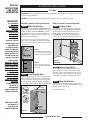
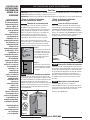
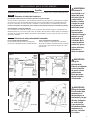
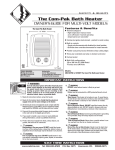
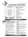
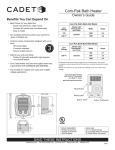
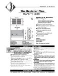
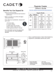
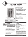
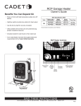
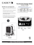
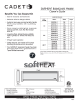
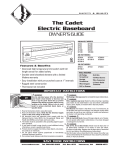
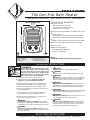
The Com-Pak Bath Heater
OWNER’S GUIDE FOR MULTI-VOLT MODELS
Features & Benefits
The Com-Pak Bath Heater
12 5/8” Height
32.07cm
10” Width
25.4cm
■
Thermal safeguard
• High temperature manual reset:
turns off heater if normal operating
temperatures are exceeded
■
Commercial grade steel element - painted to resist rusting
■
Built-in controls
- Single pole thermostat with disabled (no heat) position
- 60 minute timer overrides thermostat for instant warmth
■
Powder coat paint process eliminates sharp cutting edges
■
Three year extended warranty on element and motor
■
Factory tested
■
Multi-Volt configurations
120 or 240 Volt AC (1000 Watts)
*Factory set at 240-Volts
1/2” Depth
1.27cm
TOOLS REQUIRED:
Phillips Screwdriver
Straight Screwdriver
Wire Strippers
Utility Knife
(4) 11/2" Wood Screws
Insulated Wire Connectors
(1) Strain Relief Connector
Models:
CBC103TW or CB103T The Com-Pak Bathroom Heater
IMPORTANT INSTRUCTIONS
WARNING
Turn the electrical power off at the electrical panel
board (circuit breaker or fuse box) and lock or tag
the panel board door to prevent someone from
turning on power while you are working on the
heater. Failure to do so could result in serious
electrical shock, burns, or possible death.
1. Read all instructions before using this heater.
9.
WARNING
DO NOT install where heater is likely to get wet.
10.
WARNING
Heater must be connected to a GFCI protected branch circuit.
11.
WARNING
Burn Hazard. This heater is hot when in use. To avoid burns,
do not let bare skin touch hot surfaces. Use extreme caution
when any heater is used by or near children or invalids.
12.
WARNING
Risk of Electrical Shock. DO NOT install the heater directly
above bathtub or sink. DO NOT install in shower stall area
(Manufacturer recommends a minimum 2 foot clearance).
13.
WARNING
Risk of Electrical Shock. Connect grounding lead to grounding
screw provided. Keep all foreign objects out of heater.
14.
WARNING
Risk of Electrical Shock. Never place a switch where it can
be reached from the tub or shower enclosure.
2. Read all information labels. Verify that the electrical
supply wires are the same voltage as the heater.
3. All electrical work and materials must comply with the
National Electric Code (NEC), the Occupational Safety
and Health Act (OSHA), and all state and local codes.
4. Connect the grounding screw provided in the wall can to
the supply ground wire.
5. If you need to install a new circuit or need additional
wiring information, consult a qualified electrician.
6. Protect electrical supply from kinks, sharp objects, oil,
grease, hot surfaces or chemicals.
7.
WARNING
Overheating or fire may occur. DO NOT install the heater
in a floor, in the ceiling, below a towel bar, behind a door, or
anywhere the air discharge may be blocked in any manner.
8.
WARNING
Fire or explosion may occur. DO NOT install heater in any
area where combustible vapors, gases, liquids, or excessive
lint or dust are present.
15.
WARNING
Risk of Fire. Do not block heater. Heater must be kept clear
of all obstructions: a minimum of 3 feet in front, 6 inches
above and on both sides. Heater must be kept clean of lint,
dirt and debris. (See Maintenance Instructions.)
SAVE THESE INSTRUCTIONS
www.cadetco.com
Tel: 360-693-2505
P.O. Box 1675
Vancouver, WA
98668-1675
READ ALL
INSTRUCTIONS
AND SAFETY
INFORMATION
Installation Instructions
Part One
PLACEMENT: Install The Com-Pak Bathroom Heater (Model CB) vertically. Heater is not approved for horizontal
or ceiling mount applications.
CONTROLS: A built-in thermostat and 60 minute timer. (Note: Do not use with a wall thermostat.)
IMPORTANT!
It is extremely
important you
verify the
electrical supply
wires are the
same voltage
as the heater
(i.e. 120 volt
heater to 120 volt
power supply and
240 volt heater
to 240 volt power
supply). If replacing
an existing heater,
check the labels of
the old heater and
replace using the
same voltage.
Hooking a 240 volt
heater to a 120 volt
power supply will
drastically reduce
the heater’s
output. Hooking
a 120 volt heater to
a 240 volt power
supply will destroy
the heater.
Connecting your
heater to an
incompatible
power supply will
void the warranty.
Warranty is void if
any material is
sprayed on the
element or blower.
How do I install for new construction?
STEP 1
Mount The Wall Can
How do I install in an existing wall?
STEP 1
The CB Series heater REQUIRES A MINIMUM distance
of 6 inches from adjacent surfaces and 4½ inches from
the floor. However, Cadet RECOMMENDS 12 inches
from all adjacent surfaces and 12 inches above the
floor for longer and cleaner performance. Heaters must
be spaced at least 3 feet apart.
Cut Hole In Wall
Cut a hole 8 inches wide by 10¼ inches high next
to a wall stud. This heater REQUIRES A MINIMUM
distance of 6 inches from adjacent wall surfaces
and 4½ inches from the floor. However, Cadet
RECOMMENDS 12 inches from all adjacent wall
surfaces and 12 inches from the floor (See Figure 4).
Secure the wall can to the stud with 2 screws (See
Figures 1 & 2). As an option, the rubber shim provided
may be attached to side of wall can to square the wall
can to the stud.
Figure 1
Face of wall can must extend
½ or 5/8 inch from face of stud to
allow for thickness of sheetrock.
Figure 2
Attach wall can to stud with
screws through holes provided
in wall can.
STEP 2
Connect Supply Wires
Route the supply wire from circuit breaker to heater.
Remove a knockout and attach the supply wire with
a strain relief connector leaving 10 inch wire lead for
later use. Connect supply ground wire to grounding
screw in wall can (See Figure 3). Proceed to PART TWO.
Figure 4
Model CB
STEP 2
Connect Supply Wires
Route supply wire from circuit breaker directly to
heater. Remove a knockout and attach the supply
wire with a strain relief connector, leaving 10 inch
wire lead for later use (See Figure 3). Connect supply
ground wire to grounding screw supplied in wall can.
STEP 3
Mount The Wall Can
Insert wall can into opening; keeping wall can flush
with wall surface. Secure can to wall stud with 2 screws
through holes provided in can.
SUPPLY WIRE
Proceed to PART TWO
KNOCK-OUT
(TWIST TO REMOVE)
STRAIN RELIEF
CONNECTOR
GROUNDING
SCREW
Figure 3
2
Proceed to Part Two
Installation Instructions
Part Two
Multi-Volt Element Wiring Configuration: Refer to Figures 5, 6, 7 and 8 for desired voltage.
Determine Supply Voltage
STEP 1
Heater must be connected to a GFCI protected branch circuit.
Before installing the heater, it is extremely important you verify the heater is configured for the correct supply
voltage. The Com-Pak Bathroom Heater is configured for 240-Volt operation by default. For 120-Volt installation
you must reconfigure the heater wiring. Installing the heater without configuring for the correct voltage will
destroy the heater and void your warranty.
How to determine the supply voltage:
If replacing an existing heater, check the labels of the old heater and replace using same voltage. For new
construction, heater wires must be configure d to the same voltage as the supply wires. If you need assistance,
consult a qualified electrician.
Select Proper Heater Voltage
STEP 2
For 240-Volt configuration:
The Com-Pak Bathroom Heater is configured for
240-Volt operation by default.
For 120-Volt Configuration:
To configure heater for 120-Volt, disconnect the blue
wire from terminal D and connect it to terminal A.
Then connect the loose red wire to terminal D.
240 VOLT POWER SUPPLY
120 VOLT POWER SUPPLY
Figure 5
TIMER
Figure 6
A
D
THERMOSTAT
3
6 JUMPER WITH
INSULATED Q. D.
1
4
C
HEATING ELEMENT
SPARE
TERMINAL
ON ELEMENT
SHORTING
BAR
TIMER
THERMOSTAT
B
MANUAL
RESET
HIGH
TEMPERATURE
LIMIT
3
6
1
4
A
D
JUMPER WITH
INSULATED Q. D.
C
SPARE
TERMINAL
ON
ELEMENT
SHORTING
BAR
HEATING ELEMENT B
MANUAL
RESET
HIGH
TEMPERATURE
LIMIT
L1
MOTOR
L2
CORRECT 240 VOLT CONFIGURATION
Figure 7
L1
MOTOR
L2
WARNING
Turn the electrical
power off at the
electrical panel
board (circuit
breaker or fuse box)
and lock or tag the
panel board door
to prevent someone
from turning on
power while you
are working on the
heater. Failure to
do so could result
in serious electrical
shock, burns, or
possible death.
WARNING
Risk of Electrical
Shock. Connect
grounding lead to
grounding screw
provided. Keep all
foreign objects out
of heater.
CORRECT 120 VOLT CONFIGURATION
Figure 8
C
A
B
C
A
D
B
D
WARNING
Risk of Fire.
Heater must be
kept clear of all
obstructions: a
minimum of 3’ in
front; 6” on both
sides and above.
Heater must be
kept clean of lint,
dirt and debris.
3
Installation Instructions
How do I insert the heater assembly into the wall can?
STEP 3 Install Heater Assembly
Turn heater assembly upside down (element down with motor facing you). Connect the supply wires to the
heater wires with connectors (See Figure 9). Now rotate the heater so the element and the fan are facing you.
The element should be at the top.
Insert the bottom edge of the heater assembly into the half round slots in the bottom lip of the wall can (See
Figure 10). [IMPORTANT: Push wires into bottom of wall can during insertion. Be sure that supply wires are not
caught between motor and wall can, attach assembly at top with screw provided.]
Figure 9
STEP 4
Warranty is void
if any material
is sprayed
on the element
or blower.
Install Grill
Secure grill with the screws provided. Slide thermostat
knob onto right control shaft extending through the grill
and the timer knob onto the left shaft. Turn power on at
the electrical panel board.
Figure 10
Operation & Maintenance
How to operate your heater
1. Once installation is complete and power has been restored, turn
the thermostat knob fully clockwise. (The thermostat is on the right.)
2. When the room reaches your comfort level, turn the thermostat
knob counterclockwise until the heater turns off. The heater will
automatically cycle around this preset temperature.*
3. To reduce the room temperature, turn the knob counterclockwise.
To increase the room temperature, turn the knob clockwise.
4. For additional heat beyond thermostat setting, when room is
occupied, turn timer to desired minutes. (The timer is on the left
and represented by the symbol . The numbers indicate minutes.)
Heater will remain on until time expires, then control of the heater
will return to the thermostat and the previous set-point setting.
Maintenance
As needed, or every six months minimum.
1.
WARNING! Before removing grill, turn the electrical power off
at the electrical panel board (circuit breaker or fuse box). Lock or tag
the panel board door to prevent someone from accidentally turning
the power on while you are working on the heater. Failure to do so
could result in serious electrical shock, burns, or possible death.
2. It is important that you verify power has been turned off and no
power is going to the heater before proceeding. Circuit breakers
are often not marked correctly and turning the wrong breaker off
could mean electricity is flowing to the heater, even if the heater
does not appear to be working. If you are uncomfortable working
with electrical appliances, unable to follow these guidelines, or do
not have the necessary equipment, consult a qualified electrician.
4
*Note: If thermostat knob is turned fully counterclockwise, it will be in the
disabled (no heat) position.
3. Once you verify the power has been turned off correctly,
proceed to the next step.
4. Remove screws and take off grill.
5. Wash grill with hot soapy water and dry immediately.
6. While holding fan (to avoid damage or bending), use a hair dryer
or vacuum on blow cycle to blow debris through the top element
(do not touch element).
7. Vacuum fan area without touching the elements.
8. Replace grill and secure with screws.
9. Turn thermostat to desired setting.
10. Turn power back on at the electrical panel board.
About the Manual Reset Temperature Limit Control
The heater is protected by a temperature-limiting control. The manual
reset temperature limit control is designed to open the heater circuit
when excessive operating temperatures are detected. The problem
must be assessed and the limit must be reset to resume operation.
Resetting the Manual Reset Temperature Limit Control
If the manual reset limit control has opened the heater circuit due to
excessive operating temperatures, the heater will not work until the
manual reset limit button is pressed. After allowing the unit to cool
for at least 10 minutes and resolving the problem causing the limit
to trip; use a narrow object such as a ball-point pen to access the
manual reset button through the lower-right center section of the
heater grill. Press FIRMLY and be sure to listen and feel for a click,
indicating it has been reset.
IMPORTANT INSTRUCTIONS
WARNING
Turn the electrical power off at the electrical panel board (circuit breaker or fuse box) and lock or tag the panel
board door to prevent someone from turning on power while you are working on the heater. Failure to do so could
result in serious electrical shock, burns, or possible death.
Troubleshooting Chart
CONSULT LOCAL ELECTRICAL CODES TO DETERMINE WHAT WORK MUST BE PERFORMED BY QUALIFIED ELECTRICAL SERVICE PERSONNEL.
Symptom
Problem
Solution
Breaker trips immediately
upon energizing heater.
1.Incorrect supply voltage.
2.Overloaded circuit.
1. Verify that supply voltage matches the heater rating.
2. The total amperage of all heaters on a branch circuit must not be more than
80% of the amperage rating of the circuit breaker and supply wire ratings.
Use a lower wattage heater, or reduce the number of heaters on the circuit.
3. Shorted supply or heater wires may be accompanied by severe sparking. Inspect
all supply and heater wiring insulation for damage. Do not reset the circuit breaker
until all electrical shorts have been repaired.
4. Replace the circuit breaker.
1. Allow a few moments for element to reach operating temperature.
2. Verify that supply voltage matches the heater rating.
3. Replace element.
1. Close doors and windows. Provide additional insulation, or install a higher wattage
heater or multiple heaters if necessary. (If your circ uit is rated for more capacity.)
2. Wait for the timer to time-out or turn the timer counterclockwise to `0’ (The timer
overrides the thermostat setting). If heater continues to run, adjust thermostat
to its lowest setting. If heater continues to run (allow two minutes for thermostat
to respond) the thermostat requires replacement.
1. Clean heater (See “Operation & Maintenance” section for instruction s).
3.A short circuit exists in the supply
or heater wiring.
Heater fan operates,
but does not discharge
warm air.
Heater will not shut off.
4.Defective circuit breaker.
1.Insufficient element temperature.
2.Incorrect supply voltage.
3.Element has failed.
1.Heat loss from room is greater
than heater capacity.
2.Thermostat is not functioning
properly.
1.Dust, lint or other matter has
Heater discharges smoke
accumulated inside heater.
or emits a burnt odor.
Element heats for a moment 1.Defective motor or internal connection. 1. Heater or fan motor requires replacement.
without the fan turning, then 2.Fan or motor jammed.
2. Remove obstruction and press heater reset button (after allowing the unit to cool).
immediately stops heating.
Test heater operation--if reset button has been pressed (be sure to listen and feel
for a click indicating it has been reset), but heater does not run, heater requires
repair or replacement.
1. Adjust thermostat to a higher temperature until heater operates (See Problem #5
Heater does not run.
1.Thermostat is set too low, or
if the problem persists).
in disabled (no heat) position.
2. Press the manual reset button (See “Operation & Maintenance” section for
2.Heater has tripped the manual
instructions).
high-temperature reset switch.
3. Turn on the correct circuit breaker in the main panel.
3.Power not on at the circuit breaker.
4. Turn off power at circuit breaker. Check supply wire continuity and proper connection
4.Broken or poorly connected wire(s)
to heater wires.
to heater.
5.Defective thermostat and/or timer.
5. Repair or replace the heater. The entire heater, or any of its components may be
checked for continuity to determine the cause of any problem.
1. Dust, lint or other matter has
Heater continually trips
1. Clean heater (See “Operation & Maintenance” section for instructions).
accumulated inside heater.
the manual reset
2. Airflow is blocked.
temperature limit control.
2. Remove obstruction. Maintain a minimum distance of 6 inches from adjacent
surfaces, 4.5 inches from the floor, and 3 feet for furniture or other objects
3. Fan or motor is jammed.
placed directly in front of the heater.
3. Remove obstruction, and press heater manual reset button (See “Operation &
Maintenance” section for instructions) .
4. None of the above.
4. Replace heater assembly.
Warranty
LIMITED ONE-YEAR WARRANTY: Cadet will repair or replace any Cadet
product, including thermostats, found to be defective within one year after
the date of purchase.
Extended Product Warranty
LIMITED THREE-YEAR WARRANTY: Cadet will repair or replace any Com-Pak
Bathroom Heater (CB) series element or motor found to be defective or
malfunctioning from first date of purchase through the third year.
These warranties do not apply:
1. Damage occurs to the product through improper installation or incorrect
supply voltage;
2. Damage occurs to the product through improper maintenance, misuse,
abuse, accident, or alteration;
3. The product is serviced by anyone other than Cadet;
4. If the date of manufacture of the product cannot be determined;
5. If the product is damaged during shipping through no fault of Cadet.
6. CADET’S WARRANTY IS LIMITED TO REPAIR OR REPLACEMENT AS SET
OUT HEREIN. CADET SHALL NOT BE LIABLE FOR DAMAGES SUCH AS
PROPERTY DAMAGE OR FOR CONSEQUENTIAL DAMAGES AND/OR
INCIDENTAL EXPENSES RESULTING FROM BREACH OF THESE WRITTEN
WARRANTIES OR ANY EXPRESS OR IMPLIED WARRANTY.
7. IN THE EVENT CADET ELECTS TO REPLACE ANY PART OF YOUR CADET
PRODUCT, THE REPLACEMENT PARTS ARE SUBJEC T TO THE SAME
WARRANTIES AS THE PRODUCT. THE INSTALLATION OF REPLACEMENT
PARTS DOES NOT MODIFY OR EXTEND THE UNDERLYING WARRANTIES.
REPLACEMENT OR REPAIR OF ANY CADET PRODUCT OR PART DOES NOT
CREATE ANY NEW WARRANTIES.
8. These warranties give you specific legal rights, and you may also have
other rights which vary from state to state. Cadet neither assumes, nor
authorizes anyone to assume for it, any other obligation or liability in
connection with its products other than as set out herein.
If you believe your Cadet product is defective, please contact Cadet
Manufacturing Co. at 360-693-2505, during the warranty period, for
instructions on how to have the repair or replacement processed. Warranty
claims made after the warranty period has expired will be denied. Products
returned without authorization will be refused.
Parts and Service
Visit http://support.cadetco.com for information on where to obtain parts
and service.
Reduce-Reuse-Recycle
This product is made primarily of recyclable materials. You can
reduce your carbon footprint by recycling this product at the end of
its useful life. Contact your local recycling support center for further
recycling instructions.
©2009 Cadet Manufacturing Co.
Printed in U.S.A. Rev. 7/11 #720050
5
The Com-Pak Bath Heater
GUÍA DEL PROPIETARIO PARA MODELOS DE MULTIVOLTAJE
Características y Beneficios
The Com-Pak Bath Heater
Altura de 12 5/8”
Ancho de 10”
Profundidad
de 1/2”
HERRAMIENTAS NECESARIAS:
Destornillador Phillips
Destornillador plano
Pelacables
Cuchillo multiuso
(4) tornillos de 1½” para madera
Conectores de alambre aislados
(1) conector de alivio de tensión
■
Protección térmica
• Reglaje manual de alta temperatura:
apaga el calentador si se sobrepasan
las temperaturas de operación normales
■
Elemento de acero de calidad comercial con pintura resistente al óxido
■
Controles incorporados
- Termostato de polo único con posición de inhabilitación
(sin calor)
- El temporizador de 60 minutos supedita el termostato
para brindar calor instantáneo
■
Proceso de pintado con cobertura pulverizada
que elimina los bordes filosos cortantes
■
Garantía extendida de tres años para el elemento y el motor
■
Probado en fábrica
■
Configuraciones de multivoltaje
120 ó 240 voltios de CA (1000 vatios)
*Fijado en fábrica en 240 voltios
MODELOS:
CBC103TW or CB103T The Com-Pak Bathroom Heater
INSTRUCCIONES IMPORTANTES
ADVERTENCIA
1.
2.
3.
4.
5.
6.
Desconecte la electricidad en el tablero del panel
eléctrico (caja de cortacircuitos o fusibles) y trabe o
coloque un cartel en la puerta del tablero del panel
para evitar que alguien vuelva a conectar la energía
mientras se esté trabajando en el calentador. De lo
contrario podrían producirse graves golpes
eléctricos, quemaduras e incluso la muerte.
Lea todas las instrucciones antes de usar este calentador.
Lea todas las etiquetas que contengan información.
Verifique que todos los cables de suministro eléctrico sean
del mismo voltaje que el calentador.
Todo trabajo y materiales eléctricos deben cumplir con el
Código Eléctrico Nacional (“NEC”, por su sigla en inglés),
con la Ley de Seguridad y Salud Ocupacional (“OSHA”, por
su sigla en inglés) y con todos los códigos estatales y locales.
Conecte el tornillo de puesta a tierra que viene en la cámara
de pared al cable de conexión a tierra del suministro.
Si se debe instalar un nuevo circuito o se necesita
información adicional sobre el cableado, consulte a un
electricista calificado.
Evite que los cables de suministro eléctrico se retuerzan
o entren en contacto con objetos afilados, aceite, grasa,
superficies calientes o sustancias químicas.
7.
ADVERTENCIA
Podría producirse sobrecalentamiento o un incendio. NO
instale el calentador en el suelo, cielo raso o detrás de puertas.
8.
ADVERTENCIA
Podrían producirse explosiones o incendios. NO instale
el calentador en áreas donde exista la presencia de
vapores, gases o líquidos combustibles o exceso de
pelusas o polvo.
9.
ADVERTENCIA
NO lo instale donde el calentador se pueda mojar.
10.
ADVERTENCIA
El calentador se debe conectar a un circuito derivado con
protección GFCI.
11.
ADVERTENCIA
Riesgo de quemaduras. Este calentador se calienta mucho
cuando está en uso. Para evitar quemaduras, no lo toque con
su piel descubierta. Tenga mucho cuidado al utilizar cualquier
tipo de calentador en presencia de niños o personas inválidas.
12.
ADVERTENCIA
Riesgo de electrocución. NO instale el calentador directamente
sobre la tina o lavamanos. NO lo instale en la zona de la
ducha (el fabricante recomienda un espacio mínimo de 2 pies).
13.
ADVERTENCIA
Riesgo de electrocución. Conecte el conductor a tierra al
tornillo de puesta a tierra suministrado. Evite que entren objetos
extraños al calentador.
14.
ADVERTENCIA
Riesgo de electrocución. Nunca coloque un interruptor donde
pueda ser alcanzado por el conjunto de la tina o ducha.
15.
ADVERTENCIA
Riesgo de incendio. No bloquee el calentador. El calentador
debe mantenerse sin obstrucciones: un mínimo de 3 pies
por delante, 6 pulgadas por encima y en cada costado. Los
calentadores deben mantenerse sin pelusas, suciedad ni
residuos. (Consulte las instrucciones de mantenimiento.)
CONSERVE ESTAS INSTRUCCIONES
www.cadetco.com
Tel: 360-693-2505
P.O. Box 1675
Vancouver, WA
98668-1675
LEA TODAS LAS
INSTRUCCIONES
E INFORMACIÓN
ACERCA DE LA
SEGURIDAD
¡IMPORTANTE!
Es extremadamente
importanteverificar
que los cables de
suministro eléctrico
sean del mismo
voltaje que el
calentador (es decir,
un calentador de
120 voltios con un
suministro de energía
de 120 voltios y un
calentador de 240
voltios con un
suministro de energía
de 240 voltios). Si va
a reemplazar un
calentador existente,
revise las etiquetas
del calentador
antiguo y sustitúyalo
por otro del mismo
voltaje. Si se conecta
un calentador de
240 voltios a un
suministro de
energía de 120
voltios, se reducirá
drásticamente el
rendimiento del
calentador. Si se
conecta un
calentador de 120
voltios a un
suministro de
energía de 240
voltios, se destruirá
el calentador. Si se
conecta el calentador
a un suministro de
energía incompatible,
se anulará la garantía.
La garantía pierde
su validez si se
rocía algún producto
en el elemento
o en el soplador.
8
Instrucciones para la instalación
Parte Uno
UBICACIÓN: Instale verticalmente el calentador de baño Com-Pak (Modelo CBC). No se ha aprobado el uso
horizontal del calentador ni tampoco su montaje en cielo raso.
CONTROLES: Un termostato incorporado y temporizador de 60 minutos. (Nota: No lo use con un termostato mural.)
¿Cómo se instala el calentador
en una construcción nueva?
PASO 1 Montaje de la cámara de pared
Este calentador serie CB requiere una distancia
MÍNIMA de 6 pulgadas desde las superficies
adyacentes y 4½ pulgadas desde el piso. Sin embargo,
Cadet recomienda 12 pulgadas de distancia desde
todas las superficies adyacentes y 12 pulgadas por
sobre el piso para una vida útil más larga y un
funcionamiento más limpio. Si se instalan varios
calentadores, deje al menos tres pies entre ellos.
¿Cómo se instala el calentador
en una pared existente?
PASO 1 Corte un orificio en la pared
Corte un orificio de 8 pulgadas de ancho por 10¼ de
alto al lado de un puntal de la pared. Este calentador
REQUIERE UNA DISTANCIA MÍNIMA de 6 pulgadas
de las superficies murales adyacentes y 4½ pulgadas
del piso. Sin embargo, Cadet RECOMIENDA 12 pulgadas
desde todas las superficies murales adyacentes y 12
pulgadas desde el piso (consulte la figura 4).
Fije la cámara de pared al puntal con 2 tornillos
(consulte las figuras 1 y 2). Como alternativa, se puede
añadir la cuña de caucho suministrada al costado
de la cámara de pared para cuadrarla con el puntal
guía
Figura 1
La superficie de la cámara de
pared debe sobresalir entre
1/2 pulgada y 5/8 de pulgada
de la superficie del puntal
a fin de dejar espacio para
la lámina de yeso.
Figura 2
Conecte la cámara de pared
al puntal mediante los tornillos
por los orificios que contiene
la cámara.
Figura 4
Model CB
PASO 2 Conecte los alambres de suministro
Tienda el cable de suministro desde el cortacircuito
directamente al calentador. Quite un destapadero y fije
el cable de suministro mediante un conector de alivio
de tensión dejando 10 pulgadas de cable de conexión
para utilizarlo más adelante (consulte la figura 3).
PASO 2 Conecte los alambres de suministro Empalme el cable de conexión a tierra del suministro
Tienda el cable de suministro desde el cortacircuito
al tornillo de puesta a tierra que viene en la cámara
al calentador. Quite un destapadero y coloque el cable de pared.
de suministro mediante un conector de alivio de tensión
dejando 10 pulgadas de cable de conexión para
PASO 3 Montaje de la cámara de pared
utilizarlo más adelante. Conecte el alambre de suministro
Inserte la cámara de pared en la abertura,
a tierra al cable espiral de puesta a tierra situado en
manteniéndola alineada con la superficie de la pared.
la cámara de pared (consulte la figura 3). Continúe
Asegure la cámara al puntal de la pared con 2 tornillos
con la PARTE DOS.
mediante los orificios que vienen en la cámara.
Continúe con la PARTE DOS.
CABLE DEL
SUMINISTRO
DESTAPADERO
(GIRE PARA
RETIRARLO)
CONECTOR
DE ALIVIO
DE TENSIÓN
TORNILLO
DE PUESTA
A TIERRA
Figura 3
Continúe con la PARTE DOS.
Instrucciones para la instalación
Parte Dos
Configuración de cableado del elemento de multivoltaje: Consulte las figuras 5, 6, 7 y 8 según el voltaje que desee.
PASO 1
Determine el voltaje del suministro
El calentador se debe conectar a un circuito derivado con protección GFCI.
Antes de instalar el calentador, es extremadamente importante verificar que esté configurado para el voltaje
de suministro correcto. El calentador de baño Com-Pak está configurado de manera predeterminada para
funcionar a 240 voltios. Para la instalación a 120 voltios, se debe reconfigurar el cableado del calentador.
Instalar el calentador sin configurarlo para el voltaje correcto destruirá el aparato e invalidará la garantía.
Cómo determinar el voltaje de suministro:
Si va a reemplazar un calentador existente, revise las etiquetas del calentador antiguo y sustitúyalo por otro
del mismo voltaje. Para una construcción nueva, los alambres del calentador se deben configurar de modo que
coincidan con el voltaje de los alambres del suministro del inmueble. Si necesita ayuda, consulte a un técnico
electricista calificado.
PASO 2
Seleccione el voltaje adecuado del calentador
Para la configuración de 240 voltios:
El calentador de baño Com-Pak está configurada
para operar a 240 voltios de manera predeterminada.
SUMINISTRO DE ALIMENTACIÓN DE 240 VOLTIOS
Figura 5
TEMPORIZADOR
3
A
D
TERMOSTATO
TERMINAL
LIBRE EN LA
BARRA DE
CORTOCIRCUI
TO DEL
ELEMENTO
Para la configuración de 120 voltios:
A fin de configurar el calentador para 120 voltios,
desconecte el alambre azul del terminal D y conéctelo
al terminal A. Luego conecte el alambre rojo suelto
al terminal D.
SUMINISTRO DE ALIMENTACIÓN DE 120 VOLTIOS
Figura 6
TEMPORIZADOR
TERMOSTATO
6 PUENTE CON DESC.
3
6
1
4
PUENTE CON
DESC. RÁP.
AISLADA
TERMINAL
LIBRE EN LA
BARRA DE
CORTOCIRCUI
TO DEL
ELEMENTO
A
D
RÁP. AISLADA
1
4
CCALENTADOR AISLADOB
CCALENTADOR AISLADOB
DE DESCONEXIÓN RÁPIDA
DE DESCONEXIÓN RÁPIDA
INTERRUPTOR
LÍMITE DE ALTA
TEMPERATURA
DE REGLAJE
MANUAL
INTERRUPTOR
LÍMITE DE ALTA
TEMPERATURA
DE REGLAJE
MANUAL
L1
L1
MOTOR
L2
CONFIGURACIÓN CORRECTA DE 240 VOLTIOS
Figura 7
MOTOR
L2
ADVERTENCIA
Desconecte la
electricidad en el
tablero del panel
eléctrico (caja de
cortacircuitos o
fusibles) y trabe o
coloque un cartel
en la puerta del
tablero del panel
para evitar que
alguien vuelva a
conectar la energía
mientras se esté
trabajando en el
calentador. De lo
contrario podrían
producirse graves
golpes eléctricos,
quemaduras e
incluso la muerte.
CONFIGURACIÓN CORRECTA DE 120 VOLTIOS
ADVERTENCIA
Riesgo de
electrocución.
Conecte el conductor
a tierra al tornillo
de puesta a tierra
suministrado.
Evite que entren
objetos extraños
al calentador.
Figura 8
C
A
B
C
A
D
B
Alambre Azul
D
Alambre
Blanco
Alambre
Negro
Alambre Azul
Alambre Rojo
Alambre
Blanco
Alambre
Negro
Alambre Rojo
ADVERTENCIA
Riesgo de incendio.
El calentador debe
mantenerse sin
obstrucciones: un
mínimo de 3 pies por
delante, 6 pulgadas
en cada costado
y por encima. Los
calentadores deben
mantenerse sin
pelusas, suciedad
ni residuos.
9
Instrucciones para la instalación
¿Cómo se coloca la unidad del calentador en la cámara de pared?
PASO 3 Instale la unidad del calentador
Voltee la unidad del calentador (dejando en frente suyo el elemento situado bajo el motor). Empalme los cables
de suministro con los del calentador mediante conectores (consulte la figura 9). Ahora gire el calentador
de modo que el elemento y el ventilador queden frente a usted. El elemento debe quedar arriba.
Inserte el borde inferior de la unidad del calentador en las ranuras semicirculares del reborde inferior en
la cámara de pared (consulte la figura 10). [IMPORTANTE: Presione los cables hasta el fondo de la cámara
de pared durante la inserción. Cerciórese de que los
Figura 9
alambres de suministro no queden atrapados entre el
motor y la cámara de pared, fije el conjunto en la parte
superior con el tornillo suministrado.]
La garantía pierde
su validez si se
rocía algún
producto
en el elemento
o en el soplador.
PASO 4
Instale la rejilla
Fije la rejilla con los tornillos suministrados. Deslice la
perilla del termostato en el eje del control derecho
extendiéndola por la rejilla, y la perilla del temporizador
en el eje izquierdo. Conecte la alimentación en el tablero
del panel eléctrico.
Figura 10
REJILLA
OREJETA
Funcionamiento y mantenimiento
Cómo hacer funcionar el calentador
1. Una vez que se haya realizado la instalación y reestablecido la
energía eléctrica, gire totalmente la perilla del termostato en el
sentido de las manecillas del reloj. (El termostato está a la derecha.)
2. Cuando la habitación haya alcanzado un nivel cómodo, gire la
perilla del termostato en sentido contrario a las manecillas del reloj
hasta que el calentador se apague. El calentador se encenderá y
apagará automáticamente según esta temperatura preestablecida.*
3. Para reducir la temperatura del ambiente, gire la perilla en
sentido contrario a las manecillas del reloj. Gírela en sentido
de las manecillas del reloj para aumentarla.
4. Si desea un calor superior al indicado por el termostato, gire el
temporizador a los minutos que desee. (El temporizador está a la
izquierda y se representa por el símbolo . Los números indican
minutos.) El calentador permanecerá encendido hasta que acabe
el período, el control del calentador volverá al termostato y al
punto de ajuste anterior.
Mantenimiento
Según sea necesario, o cada seis meses como mínimo.
1.
. ¡ADVERTENCIA! Antes de quitar la rejilla, desconecte la
electricidad en el tablero del panel eléctrico (cortacircuito o caja
de fusibles). Trabe o coloque un cartel en la puerta del tablero del
panel para evitar que alguien conecte accidentalmente la energía
mientras se esté trabajando en el calentador. De lo contrario podrían
producirse graves golpes eléctricos, quemaduras e incluso la muerte.
2. Antes de proceder, es importante que usted verifique que se haya
desconectado la alimentación y que el calentador no reciba energía.
Los cortacircuitos no suelen estar correctamente marcados, y
apagar el incorrecto podría significar que sigue fluyendo electricidad
10
*Nota: Si la perilla del termostato se gira completamente en el sentido contrario
a las manecillas del reloj, quedará en la posición de inhabilitación (sin calor).
al calentador, aun cuando éste parezca no estar funcionando. Si no
se siente cómodo al trabajar con artefactos eléctricos, no está en
condiciones de acatar estas pautas o no cuenta con los equipos
necesarios, solicite los servicios de un técnico electricista calificado.
3. Una vez que verifique que se ha apagado la alimentación
correctamente, prosiga con el paso siguiente.
4. Retire los tornillos y extraiga la rejilla.
5. Lave la rejilla con agua caliente y jabón, y séquela de inmediato.
6. Mientras sujeta la rueda del soplador (para evitar que se dañe o
tuerza), utilice una secadora o una aspiradora en el ciclo de soplado
para quitar la suciedad en el elemento superior (sin tocarlo).
7. Aspire el área del ventilador sin tocar los elementos.
8. Vuelva a instalar la rejilla y fíjela con los tornillos.
9. Coloque el termostato en la graduación deseada.
10. Vuelva a conectar la alimentación en el tablero del panel eléctrico.
Acerca del control de límite de temperatura de reglaje manual
El calentador está protegido por un control limitador de temperatura
con reglaje manual, el cual está diseñado para abrir el circuito del
calentador cuando se detectan temperaturas de funcionamiento
excesivas. El problema debe evaluarse y el límite debe restablecerse
para que el calentador vuelva a funcionar.
Cómo restablecer el control limitador de temperatura de reglaje manual
Si el control limitador de reglaje manual ha abierto el circuito del
calentador debido a temperaturas de funcionamiento excesivas, el
calentador no funcionará sino hasta que se oprima el botón de límite de
reglaje manual. Después de dejar que la unidad se enfríe durante unos 10
minutos y resolver el problema que causa que se disyunte el interruptor
de límite, utilice un objeto puntiagudo como un bolígrafo para acceder
al botón de reglaje manual a través de la sección central inferior derecha
de la rejilla del calentador. Oprima el botón FIRMEMENTE y asegúrese
de escuchar y sentir un chasquido indicando que se ha restablecido.
INSTRUCCIONES IMPORTANTES
ADVERTENCIA
Desconecte la electricidad en el tablero del panel eléctrico (caja de cortacircuitos o fusibles) y trabe o coloque un
cartel en la puerta del tablero del panel para evitar que alguien vuelva a conectar la energía mientras se esté trabajando en
el calentador. De lo contrario podrían producirse graves golpes eléctricos, quemaduras e incluso la muerte.
Tabla de resolución de problemas
CONSULTE LOS CÓDIGOS ELÉCTRICOS LOCALES PARA DETERMINAR QUÉ TRABAJOS DEBEN SER REALIZADOS POR PERSONAL DE SERVICIO ELÉCTRICO CALIFICADO
Síntoma
Problema
El interruptor se disyunta 1.Voltaje de suministro incorrecto.
2.Circuito sobrecargado.
inmediatamente al
encenderse el calentador.
3.Hay un cortocircuito en los cables
de suministro o del calentador.
El ventilador del
calentador funciona pero
no envía aire caliente.
El calentador no se apaga.
4.Cortacircuito defectuoso.
1. Temperatura insuficiente del elemento.
2.Voltaje de suministro incorrecto.
3.El elemento ha fallado.
1.La fuga de calor de la habitación es
superior a la capacidad del calentador.
2.El termostato no funciona
correctamente.
El calentador emite humo 1.Se han acumulado polvo, pelusas u
o un olor a quemado.
otros materiales dentro del calentador.
El elemento calienta por
1. Motor o conexión interna defectuosos.
un momento sin que gire
2.Ventilador o motor trabado.
el ventilador y luego deja
de calentar.
Solución
1. Compruebe que el voltaje de suministro coincida con la calificación del calentador.
2. El amperaje total de todos los calentadores en un circuito de rama no debe sobrepasar
el 80% de la calificación de amperaje del cortacircuito y de las calificaciones de los
cables de suministro. Utilice un calentador de vatiaje inferior o reduzca la cantidad
de calentadores en el circuito.
3. Los cables de suministro o del calentador que presentan cortocircuitos pueden ocasionar
chispas peligrosas. Revise el aislamiento de todos los cables de suministro y del calentador
para comprobar que no estén dañados. No reestablezca el cortacircuito sino hasta que
se hayan reparado todos los cortocircuitos eléctricos.
4. Reemplace el cortacircuito.
1. Espere unos momentos para que el elemento alcance la temperatura de funcionamiento.
2. Compruebe que el voltaje de suministro coincida con la calificación del calentador.
3. Reemplace el elemento.
1. Cierre las puertas y ventanas. Coloque aislamiento adicional o instale un calentador
de mayor vatiaje o múltiples calentadores si fuese necesario. (Si su circuito es apto
para mayor capacidad.)
2. Espere que el temporizador termine su período o bien gírelo en sentido contrario a las
manecillas del reloj a `0’ (el temporizador supedita el ajuste del termostato). Si el calentador
continúa funcionando, fíjelo en el ajuste mínimo. Si el calentador continúa funcionando
(espere un poco para que el termostato tenga tiempo de responder al ajuste), el termostato
se debe reemplazar.
1. Limpie el calentador (consulte las instrucciones en la sección “Funcionamiento y
Mantenimiento”).
1. Debe reemplazarse el calentador o el motor del ventilador.
2. Quite la obstrucción y oprima el botón de reglaje del calentador (después de dejar
que la unidad se enfríe). Pruebe el funcionamiento del calentador--si el botón de reglaje
se ha oprimido (asegúrese de escuchar y de sentir un chasquido indicando que se ha
restablecido), pero el calentador no funciona, el calentador debe repararse o reemplazarse.
1. Ajuste el termostato a una temperatura más alta hasta que el calentador funcione
(vea el Problema No. 5 si la dificultad persiste).
El calentador no funciona. 1.El termostato está fijado muy bajo,
o bien en la posición de inhabilitación
(sin calor).
2.El calentador ha hecho saltar el
2. Oprima el botón de reglaje manual (vea las instrucciones en la sección “Funcionamiento
interruptor de reglaje de alta
y Mantenimiento”).
temperatura.
3.La energía no está conectada
3. Conecte el cortacircuito correcto en el panel principal.
en el cortacircuito.
4.El o los cables que van al calentador 4. Desconecte la energía en el cortacircuito. Revise la continuidad del cable de suministro
están rotos o mal conectados.
y la conexión apropiada a los cables del calentador.
5. Termostato y/o temporizador
5. Repare o reemplace el calentador. Se debe revisar la continuidad de todo el calentador,
o bien de sus componentes a fin de determinar la causa de cualquier problema.
defectuosos.
1. Limpie el calentador (vea las instrucciones en la sección “Funcionamiento y
El calentador disyunta
1. Se han acumulado polvo, pelusas u
Mantenimiento”).
continuamente el control
otros materiales dentro del calentador.
2. Retire la obstrucción. Mantenga una distancia mínima de 6 pulgadas de las superfi cies
limitador de temperatura 2. El flujo de aire está bloqueado.
adyacentes, 4.5 pulgadas del piso y 3 pies de los muebles u otros objetos situados
de reglaje manual.
directamente delante del calentador.
3. El ventilador o el motor está trabado. 3. Retire la obstrucción y oprima el botón de reglaje manual del calentador (vea las
instrucciones en la sección “Funcionamiento y Mantenimiento”).
4. Reemplace el conjunto del calentador.
4. Ninguna de las anteriores.
Garantía
GARANTÍA LIMITADA DE UN AÑO: Cadet reparará o reemplazará todo producto
Cadet, incluyendo los termostatos, que presente averías en un plazo de un año
a partir de la fecha de compra.
Garantía extendida del producto
GARANTÍA LIMITADA DE TRES AÑOS: Cadet reparará o reemplazará todo
calentador de baño Com-Pak (CB) que se determine que está averiado o
funcionando mal, durante tres años a partir de la fecha de compra.
ESTAS GARANTÍAS NO SON PERTINENTES PARA:
1. Daños que sufra el producto por instalación o voltaje de suministro incorrectos;
2. Daños que sufra el producto por mantenimiento incorrecto, uso indebido,
abuso, accidente o alteraciones;
3. Servicio que se le haya dado al producto por parte de personas o entidades
ajenas a Cadet;
4. Casos en que no se pueda determinar la fecha de fabricación del producto;
5. Casos en que el producto resulte dañado durante el embarque por causas
ajenas a Cadet;
6. LA GARANTÍA DE CADET SE LIMITA A LA REPARACIÓN O REEMPLAZO, TAL
COMO SE ESTABLECE EN ESTE DOCUMENTO. CADET NO SE HARÁ
RESPONSABLE POR DAÑOS A LA PROPIEDAD O DAÑOS CONSECUENTES,
COMO TAMPOCO POR GASTOS ACCIDENTALES DEBIDO AL INCUMPLIMIENTO
DE ESTAS GARANTÍAS ESCRITAS O DE CUALQUIER GARANTÍA EXPRESA
O IMPLÍCITA.
7. EN CASO DE QUE CADET DECIDA REEMPLAZAR ALGUNA PIEZA DEL
PRODUCTO CADET, LOS REPUESTOS SE REGIRÁN POR LAS MISMAS
GARANTÍAS DEL PRODUCTO. LA INSTALACIÓN DE LOS REPUESTOS NO
MODIFICA NI PROLONGA LAS GARANTÍAS VIGENTES. EL REEMPLAZO O
REPARACIÓN DE TODO PRODUCTO O PIEZA CADET NO ORIGINA NINGÚN
TIPO DE NUEVA GARANTÍA.
8. Estas garantías le otorgan derechos legales específicos y es posible que
usted tenga otros derechos que varíen de un estado a otro. Cadet no asume
ni autoriza a nadie que lo haga en su nombre, ninguna otra obligación o
responsabilidad en relación con sus productos que no sean las que se
establecen en este documento.
Si durante el período de garantía usted considera que su producto Cadet
presenta defectos, comuníquese con Cadet Manufacturing Co. llamando a l
360-693-2505 para obtener instrucciones sobre cómo tramitar la reparación o el
reemplazo del producto. Los reclamos de garantía presentados después de la
finalización del período no serán acogidos. Los productos que se devuelvan sin
autorización serán rechazados.
Repuestos y servicio
En http://support.cadetco.com encontrará información sobre dónde obtener
repuestos y servicio.
Reduzca-reutilice-recicle
Este producto está hecho principalmente de materiales reciclables.
Puede reducir la cantidad de carbono que contribuye al medio
ambiente reciclando este producto al término de su vida útil.
Comuníquese con su centro local de reciclaje para obtener mayores
instrucciones al respecto.
©2009 Cadet Manufacturing Co.
IMPRESO EN EE.UU. Rev. 7/11 #720050
11
BLANK