1
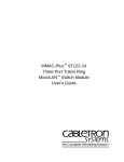
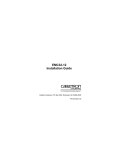
Transmit (XMT) This green LED flashes when the
FOT-DF24 transmits data. The LED flash is pulse
stretched for viewing effect. The XMT LED is off when
the device is active but not transmitting.
Receive (RCV) This yellow LED flashes when the
FOT-DF24 receives data from the network. If attached
to a repeater, RCV flashes when data passes through
the FOT-DF24. The LED is pulse-stretched for viewing
effect.
Collision (CLN) This red LED flashes when the
transceiver detects a collision condition or a jabber
packet on the network. The flash frequency may
increase as network traffic increases since more
collisions are likely to occur. The LED is pulsestretched for viewing effect.
Link OK (LNK) When lit, this green LED indicates that
a link exists between the FOT-DF24 and the device at
the other end of the fiber optic segment. LNK remains
lit as long as the link is maintained. To maintain the
link, the transceiver generates a 1 MHz idle signal
when it is not transmitting data. Both ports can show a
valid link.
Active Port (ACT) This yellow LED indicates which
fiber optic port is handling all network traffic through
the transceiver. Only one port can be active; the
inactive port ACT LED is off. A flashing ACT LED
indicates that the port is in the idle state. A slow flash
indicates that the time-out period is set to 10 seconds;
a fast flash indicates that the time-out period is set to
2 seconds.
GETTING HELP
If you have questions, or need additional help, contact
Cabletron Systems Technical Support as follows:
By phone:
Monday through Friday,
8 am to 8 pm EST at
(603) 332-9400
By CompuServe:
GO CTRON from any ! prompt
By Internet mail:
[email protected]
LANVIEW is a registered trademark of Cabletron
Systems, Inc.
FOT-DF24 is a trademark of Cabletron Systems, Inc.
CompuServe is a registered trademark of
CompuServe, Inc.
Ethernet is a trademark of Xerox Corp.
FCC NOTICE
This device complies with Par t 15 of the FCC rules.
Operation is subject to the following two conditions: (1) this
device may not cause harmful interference, and (2) this
device must accept any interference received, including
interference that may cause undesired operation.
NOTE: This equipment has been tested and found to comply
with the limits for a Class A digital device, pursuant to Part 15
of the FCC rules. These limits are designed to provide
reasonable protection against harmful interference when the
equipment is operated in a commercial environment. This
equipment uses, generates, and can radiate radio frequency
energy and if not installed in accordance with the operator’s
m a n u a l , m ay c a u s e h a r m f u l i n t e r fe r e n c e t o r a d i o
communications. Operation of this equipment in a residential
area is likely to cause interference in which case the user will
be required to correct the interference at his own expense.
WARNING: Changes or modifications made to this device
which are not expressly approved by the party responsible for
compliance could void the user’s authority to operate the
equipment.
FOT-DF24
802.3 10BASE-FL/FOIRL
Redundant Transceiver
The FOT-DF24™ fiber optic transceiver is designed to
link two Ethernet™ devices through fiber optic cable.
Dual fiber optic ports with ST type connectors provide
redundant data paths for critical applications.
DOC NOTICE
This digital apparatus does not exceed the Class A limits for
radio noise emissions from digital apparatus set out in the
Radio Interference Regulations of the Canadian Department
of Communications.
Primary Port
FOT-DF24
SQE
P
W
R
802.3 10BASE-FL/FOIRL
REDUNDANT TRANSCEIVER
WITH LANVIEW®
1
S
Q
E
X R
M V
T C
C
L
N
LNK
TX
ACT
RX
LNK
TX
ACT
RX
SN
NOTICE
Cabletron Systems reserves the right to make changes in
specifications and other information contained in this
document without prior notice. The reader should in all cases
consult Cabletron Systems to determine whether any such
changes have been made. The hardware, firmware, or
software described in this manual is subject to change
without notice.
IN NO EVENT SHALL CABLETRON SYSTEMS BE LIABLE
F O R A N Y I N C I D E N TA L , I N D I R E C T, S P E C I A L , O R
C O N S E Q U E N T I A L DA M AG E S W H AT S O E V E R
(INCLUDING, BUT NOT LIMITED TO, LOST PROFITS)
ARISING OUT OF OR RELATED TO THIS MANUAL OR
T H E I N F O R M AT I O N C O N TA I N E D I N I T, E V E N I F
CABLETRON SYSTEMS HAS BEEN ADVISED OF, KNOWN
OR SHOULD HAVE KNOWN, THE POSSIBILITY OF SUCH
DAMAGES.
© Copyright August 1994 by
Cabletron Systems, Inc.
P.O. Box 5005, Rochester, NH 03866-5005
All Rights Reserved
Printed in the United States of America
Part number: 9030729-02 August 1994
2
MIN
MAX
Back-up Port
If the primary port (port 1) receives no data for either 2
or 10 seconds (switch selectable), the port enters the
idle state. During the idle state, if the back-up port
(port 2) receives data it becomes the active port.
When the primary port senses data again, it switches
back to become the active port. The two transceiver
ports can be connected to the same network device,
different network devices or even different networks.
REQUIREMENTS
The FOT-DF24 Transceiver complies with IEEE 802.3
10BASE-FL/FOIRL specifications. Use the FOT-DF24
with Version 1, Version 2, and/or IEEE 802.3
equipment. For best network performance, observe
the following network guidelines.
Fiber Optic Requirements
The FOT-DF24 supports 50/125 µm, 62.5/125 µm, and
100/140 µm fiber optic cable. Link length depends on
cable type and system fiber optic budget. The FOTDF24 supports a maximum link length of 2 km.
AUI Cable
The AUI port connects the Transceiver to an Ethernet
device. The cable can be up to 50 meters long and
must comply with IEEE 802.3 or with Ethernet Version
1 or 2 specifications.
Fiber Optic Cable Link Attenuation
At an 850 nm wave length, link segment attenuation
can be no more than:
• 13.0 db for 50/125 µm cable
• 16.0 db for 62.5/125 µm cable
• 19.0 db for 100/140 µm cable
OPERATING SPECIFICATIONS
Cabletron Systems reserves the right to change these
specifications any time without notice.
General
Receive Sensitivity:
-29.5 dBm
Max. Receive Power:
-8.2 dBm
Bit Error Rate:
Better than 10-9 error rate
Transmitter Peak
Wavelength:
820 nm typical;
790 nm min;
860 nm max
Spectral Width:
75 nm max
Rise Time:
10 nsec max
Fall Time:
10 nsec max
Transmitter Power
Into 50/125 µm fiber:
-13.0 dBm ;
-16.5 dBm worst case budget
Into 62.5/125 µm fiber: -10.0 dBm ;
19.5 dBm worst case budget
Into 100/140 µm fiber: -7.0 dBm;
22.5 dBm worst case budget
Note: The transmitter power and receive sensitivity
levels are peak power levels. To convert to average
power levels, subtract 3 dbm.
Power Supply
Input Current:
500mA
Input Voltage:
12.0 Vdc typical; 9.5 Vdc
min; 15.75 Vdc max
AUI 15 Pin D-Type Connector
8 Logic Ref
7 No Connection
6 Power Return
5 Receive +
4 Logic Ref.
3 Transmit +
2 Collision +
1 Logic Ref.
O
O
O
O
O
O
O
O
O
O
O
O
O
O
O
15 No Connection
14 Logic Ref.
13 Power (+12Vdc)
12 Receive 11 Logic Ref.
10 Transmit 9 Collision -
OPERATING ENVIRONMENT
Operating Range:
5˚ to 40˚C (41˚ to 104˚ F)
Heat Output:
17 Btu/hr
Storage Range:
-30˚ to 80˚C (-22˚ to 160˚F)
Humidity Range:
5 to 95% (non-condensing)
SAFETY
Designed in accordance with UL 1950, CSA C22.2
No. 950, and EN 60950; the EMI requirements of FCC
Class A and EN 55022 Class A; and the EMC
requirements of EN 50082-1.
Note: It is the responsibility of the person who sells
the system to which the FOT-DF24 will be a part to
ensure that the total system meets allowed limits of
conducted and radiated emissions.
INSTALLING THE FOT-FB24
To install your FOT-DF24, set the SQE and MIN/MAX
switches, connect the AUI cable to an Ethernet device,
connect the fiber optic ports to the network and use
the cable ties and mounts to provide cable strain relief.
Observe the requirements listed previously in this
guide and the guidelines listed in the following
sections.
Setting the SQE Switch
The SQE (Signal Quality Error) switch is a two position
switch on the top of the transceiver. The FOT-DF24 is
shipped with the SQE switch in the on (●) position. To
disable the SQE test function, slide the SQE switch to
the off position (O) as indicated on the front of the
transceiver.
Warning: Use a non-conductive probe, or disconnect
the transceiver’s AUI connector before setting the SQE
and MIN/MAX switches.
Caution: You must disable the SQE test function if you
connect the FOT-DF-24 to a repeater or to an Ethernet
Version 1 device. In addition, some Version 2
equipment does not support SQE Test. Devices that
do not support the SQE Test function will interpret the
SQE test pulse as a collision, resulting in poor network
performance.
Setting the MIN/MAX Switch
The MIN/MAX switch sets the time duration that the
transceiver waits before switching to the redundant
fiber port. MIN equals approximately 2 seconds. MAX
equals approximately 10 seconds.
Connecting the FOT-DF24 to the Network
1. Remove the plastic covers from the fiber optic
ports on the FOT-DF24 and from the ends of the
connectors on each fiber cable.
2.
Attach a fiber cable from one transceiver TX port,
to the RX port on the network device. Likewise,
attach a fiber cable from the RX port on the
transceiver to the TX port on the network device.
Repeat this procedure for the second transceiver
port and network device.
3.
Attach the AUI cable to the Ethernet device.
4.
Check the LANVIEW® LEDs. The PWR LED
should be lit to indicate that the transceiver is
receiving power through the AUI cable. The LNK
LEDs should be lit to indicate a link between the
transceiver and the network devices. One ACT
LED should be lit to indicate that the port is the
active port (it has received a valid data
packet).The SQE LED will be lit if the SQE test
function is enabled.
USING LANVIEW
LANVIEW is Cabletron Systems’ diagnostic and status
monitoring system.
Power (PWR) When lit, this green LED indicates that
the FOT-DF24 is receiving power through the AUI
connector. If the PWR LED is not lit, power is not
being received or the DC-to-DC converter in the
transceiver has failed.
Signal Quality Error (SQE) Test Function When lit,
this yellow LED indicates that the transceiver’s SQE
test function is on. The SQE test ensures that the
collision presence circuit and the path between the
Ethernet device and the transceiver are operational.