1
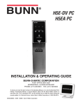
ULTRA-1
ULTRA-2
INSTALLATION & OPERATING GUIDE
BUNN-O-MATIC CORPORATION
POST OFFICE BOX 3227
SPRINGFIELD, ILLINOIS 62708-3227
PHONE: (217) 529-6601 FAX: (217) 529-6644
To ensure you have the latest revision of the Operating Manual, or to view the Illustrated Parts
Catalog, Programming Manual, or Service Manual, please visit the Bunn-O-Matic website, at
www.bunn.com. This is absolutely FREE, and the quickest way to obtain the latest catalog and
manual updates. For Technical Service, contact Bunn-O-Matic Corporation at 1-800-286-6070.
40563.0000C 04/08 ©2007 Bunn-O-Matic Corporation
BUNN-O-MATIC COMMERCIAL PRODUCT WARRANTY
Bunn-O-Matic Corp. (“BUNN”) warrants equipment manufactured by it as follows:
1) All equipment other than as specified below: 2 years parts and 1 year labor.
2) Electronic circuit and/or control boards: parts and labor for 3 years.
3) Compressors on refrigeration equipment: 5 years parts and 1 year labor.
4) Grinding burrs on coffee grinding equipment to grind coffee to meet original factory screen sieve analysis:
parts and labor for 3 years or 30,000 pounds of coffee, whichever comes first.
These warranty periods run from the date of installation BUNN warrants that the equipment manufactured by
it will be commercially free of defects in material and workmanship existing at the time of manufacture and
appearing within the applicable warranty period. This warranty does not apply to any equipment, component or
part that was not manufactured by BUNN or that, in BUNN’s judgment, has been affected by misuse, neglect,
alteration, improper installation or operation, improper maintenance or repair, damage or casualty. This warranty is
conditioned on the Buyer 1) giving BUNN prompt notice of any claim to be made under this warranty by telephone
at (217) 529-6601 or by writing to Post Office Box 3227, Springfield, Illinois 62708-3227; 2) if requested by
BUNN, shipping the defective equipment prepaid to an authorized BUNN service location; and 3) receiving prior
authorization from BUNN that the defective equipment is under warranty.
THE FOREGOING WARRANTY IS EXCLUSIVE AND IS IN LIEU OF ANY OTHER WARRANTY, WRITTEN OR
ORAL, EXPRESS OR IMPLIED, INCLUDING, BUT NOT LIMITED TO, ANY IMPLIED WARRANTY OF EITHER
MERCHANTABILITY OR FITNESS FOR A PARTICULAR PURPOSE. The agents, dealers or employees of BUNN
are not authorized to make modifications to this warranty or to make additional warranties that are binding on
BUNN. Accordingly, statements by such individuals, whether oral or written, do not constitute warranties and
should not be relied upon.
If BUNN determines in its sole discretion that the equipment does not conform to the warranty, BUNN, at its
exclusive option while the equipment is under warranty, shall either 1) provide at no charge replacement parts
and/or labor (during the applicable parts and labor warranty periods specified above) to repair the defective
components, provided that this repair is done by a BUNN Authorized Service Representative; or 2) shall replace
the equipment or refund the purchase price for the equipment.
THE BUYER’S REMEDY AGAINST BUNN FOR THE BREACH OF ANY OBLIGATION ARISING OUT OF THE SALE OF
THIS EQUIPMENT, WHETHER DERIVED FROM WARRANTY OR OTHERWISE, SHALL BE LIMITED, AT BUNN’S
SOLE OPTION AS SPECIFIED HEREIN, TO REPAIR, REPLACEMENT OR REFUND.
In no event shall BUNN be liable for any other damage or loss, including, but not limited to, lost profits, lost sales,
loss of use of equipment, claims of Buyer’s customers, cost of capital, cost of down time, cost of substitute
equipment, facilities or services, or any other special, incidental or consequential damages.
BrewWISE, BUNN Gourmet Ice, BUNN Pour-O-Matic, BUNN, Bunn-OMatic, Bunn-O-Matic, BUNNlink, BUNNserve, BUNN
Espress, DBC, Dr. Brew, Dual, EasyClear, EasyGard, Easy Pour, FlavorGard, Gourmet Ice, Gourmet Juice, High Intensity,
IMIX, Infusion Series, Legendary for Quality, The Mark of Quality in Beverage Equipment Worldwide, My Café, PowerLogic, Safety-Fresh, Scale-Pro, Single, Smart Funnel, Smart Hopper, SmartWAVE, Soft Heat, SplashGard, System III,
ThermoFresh, 392, AXIOM, Beverage Profit Calculator, Beverage Bar Creator, BrewLOGIC, BrewMETER, BrewWIZARD,
BUNNSERVE, BUNNsource, Coffee At Its Best, Cool Froth, Digital Brewer Control, Intellisteam, Nothing Brews Like a
BUNN, Pouring Profits, Pulse Wave, Quality Beverage Equipment Worldwide, , Signature Series, Silver Series, Smart Heat,
Tea At Its Best, The Horizontal Red Line, Titan, Ultra, are either trademarks or registered trademarks of Bunn-O-Matic
Corporation.
2
40563 041108
INTRODUCTION
This equipment dispenses granita-type and cold liquid drinks on demand from separate hoppers. Operating controls
are accessible only through password protection.
CONTENTS
Introduction & Warranty................................................................................................. 3
Site Preparation, Electrical Requirements....................................................................... 3
Initial Setup..................................................................................................................... 4
Operating Controls.......................................................................................................... 8
Using the Dispenser for Granita-Type Products............................................................ 10
Using the Dispenser for Cold Liquid Products.............................................................. 10
Other Recommendations For Your Dispenser............................................................... 11
Recommended Daily Cleaning...................................................................................... 12
User Notices................................................................................................................. 14
SITE PREPARATION
The dispenser is very heavy. Place it on a sturdy counter or shelf capable of supporting at least 180 lbs. It is
for indoor use only.
The dispenser must have at least six inches of space behind it. This space is needed for airflow, air filter
removal, and cleaning. A clearance of at approximately six inches is recommended between the dispenser sides
and the wall or another appliance. The dispenser performs better if not placed near any heating appliance. Leave
some space so the dispenser can be moved for cleaning.
ELECTRICAL REQUIREMENTS
CAUTION – Improper electrical installation will damage components. An electrician must provide electrical service
as specified below.
Model ULTRA-1 & 2, This dispenser has an attached cordset and requires a 2-wire, grounded, individual branch
circuit rated 120 volts ac, 15 amp, single phase, 60 Hz. The mating connector must be a NEMA 5-15R.
(Refer to the dataplate for exact electrical requirements.)
Model ULTRA-1A & 2A, This dispenser has an attached cordset and requires a 2-wire, grounded, individual
branch circuit rated 230 volts ac, 10 amp, single phase, 50 Hz. (Refer to the dataplate for exact electrical requirements.)
Model ULTRA-1B & 2B, This dispenser has an attached cordset and requires a 2-wire, grounded, individual
branch circuit rated 100 volts ac, 10 amp, single phase, 50 Hz. (Refer to the dataplate for exact electrical requirements.)
NOTE – Bunn-O-Matic does not recommend the use of any extension cord with these dispensers.
3
40563 041108
Initial setup
CAUTION – The dispenser is very heavy! Use care when lifting or moving it. Use at least two people to lift or
move the dispenser.
6.0”
MIN.
1. Set the dispenser on a sturdy counter top. The dispenser requires a minimum of 6.0” air clearance at the
rear of the dispenser. For optimum performance, do not let warm air from surrounding machines blow on
the ULTRA dispenser.
NOTE – The dispenser should be level or slightly lower in front for proper operation.
2. Remove all shipping material, including the compressor support eyebolt, the cooling drum supports, the
“Do Not Lift Here” signs from the cooling drums, and the “Rinse Before Using” signs from the hopper(s).
For models without PAF (Powder Auto-Fill™), proceed to step #7.
3. Remove the rear plastic plug 4. Place PAF platform assembly 5. Tighten support rod from top
from the trim strip between the
on top of the motor covers and
of platform. Retighten motor
hopper drip trays and loosen the
install support rod into hole in
cover screws.
auger motor cover screws.
trim strip.
6. Plug RCA cord into ULTRA base 7. Install each hopper seal over 8. Press the seals firmly into
unit. Proceed with steps 7 thru
place.
the flange at the rear of the
12.
cooling drums as shown.
4
40563 110207
Initial setup (cont.)
9. Align the auger shaft with the 10. Install auger nose bushing into
flat fin of the auger. Push the
inside front of hopper.
augers as far as they will go
and rotate them so the flat fin
is facing up.
11. Thoroughly rinse the hoppers
and install them over the augers
and cooling drums.
12. Slide the hopper(s) into place 13. For models with PAF, install 14.Install PAF unit onto platform
and push down until the hoplevel probes into slots at top
and plug power cord into rear
per lock plunger snaps into
rear of PAF hoppers.
of platform. Plug platform power
place. For models without PAF,
cord into proper outlet. (Refer
proceed to step 15.
to PAF manual for water connections)(Proceed to step 17)
15. Set the lid(s) on the hopper(s).
Lift slightly and slide back or
front for filling.
16. Plug in the hopper lid lamp 17. Assemble the drip tray.
cord(s).
5
40563 110207
Initial setup (cont.)
Set Consistency
This function allows the operator to adjust the ice consistency, or torque of each auger when answered YES
(“ICE”). Two screens will appear for left and right. The operator can scroll through a range of a minimum of 1
(ULTRA) to a maximum of 16 (ICE). Factory default is 10.
NOTE: ULTRA-1 models will only have one adjustment screen.
SET THICKNESS ?
NO
YES
P3678
MIN RIGHT 5 MAX
MIN LEFT 9 MAX
6
40563 041108
Initial setup (cont.)
Set Time and Date
Selecting YES (ICE) allows the operator to set the DATE (YY MM DD) and TIME (HR MIN SEC) for display
on the Home Screen.
SET DATE TIME ?
NO
YES
YEAR 2005
(-) NEXT (+)
MONTH 1
(-) NEXT (+)
MONTH DAY 25
(-) NEXT (+)
HOUR 10 AM
(-) NEXT (+)
MINUTE
45
(-) NEXT (+)
SECOND
30
(-) NEXT (+)
Install Date
The following three screens will scroll after advancing past the function “Restore Defaults”. The Install Date
and Time is recorded when the dispenser is powered on for the first 100 hours. The Install Date and Time cannot
be reset and is stored in permanent memory.
INSTALL DATE
ULTRA
VERSION # __.__
JAN. 20, 2005
3:55:25 PM
7
40563 041108
OPERATING CONTROLS
ULTRA-1
There are three of these switches that will be used for the operation of the dispenser.
1
2
3
4
P3932
1.
switch (upper left corner of the control pad)
This switch is the ON/OFF toggle switch which powers up the dispenser and the LCD display. When ON
the Date and Time toggle back and forth continously except during programming.
2.
(upper right corner)
This is used to turn the auger motor to AUGER ON, AUGER OFF or AUGER REFILL ON. (Refill only applicable when installed)
3.
(lower right corner)
This is used to turn the ice control to OFF, ICE or CHILL.
4. Hidden buttons used for Programming.
8
40563 041108
OPERATING CONTROLS
ULTRA-2
There are five of these switches that will be used for the operation of the dispenser.
1
P3677
2
3
6
4
5
1.
switch (upper left corner of the control pad)
This switch is the ON/OFF toggle switch which powers up the dispenser and the LCD display. When ON
the Date and Time toggle back and forth continously except during programming.
2.
(bottom left corner)
This is used to turn the left side auger motor to AUGER ON, AUGER OFF or AUGER REFILL ON. (Refill
only applicable when installed)
3.
(bottom left corner)
This is used to turn the left side ice control to OFF, ICE or CHILL.
4.
(bottom right corner)
This is used to turn the right side auger motor AUGER ON, AUGER OFF or AUGER REFILL ON. (Refill only
applicable when installed)
5.
(bottom right corner)
This is used to turn the right side ice control to OFF, ICE or CHILL.
6. Hidden buttons used for Programming.
9
40563 041108
USING THE DISPENSER FOR GRANITA-TYPE PRODUCTS
1. Lift the lid slightly for the selected hopper and slide back to gain access to the hopper.
2. Place the pre-mixed liquid product in the selected hopper.
3. a. Press and release the
(ON/OFF) switch to power on the dispenser.
b. Press and release the appropriate
when applicable.
(ON/OFF) switch to start the Auger Motor and to turn on AutoFill
c. Press and release the
(OFF/ICE/CHILL) switch and select ICE to begin the cooling process for the
selected hopper.
4. Wait for the liquid to freeze to the desired consistency.
HINTS – Bunn-O-Matic recommends that the product in the dispenser be thawed each day, usually overnight.
The ice granules get too large and a consistent product is difficult to maintain if left frozen for an extended
period of time. Set the NIGHT mode for a few hours each night and return it to the DAY mode when the
product has thawed sufficiently. You’ll know it is in the NIGHT mode because the display will indicate NIGHT
MODE, and the hopper light(s) will turn off.
USING THE DISPENSER FOR COLD LIQUID PRODUCTS
1. Lift the lid slightly for the selected hopper and slide back to gain access to the hopper.
2. Place the pre-mixed liquid product in the selected hopper.
3. a. Press and release the
(ON/OFF) switch to power on the dispenser.
b. Press and release the appropriate
when applicable.
c. Press and release the
the selected hopper.
4. Wait for the liquid to cool.
(ON/OFF) switch to start the Auger Motor and to turn on AutoFill
(OFF/ICE/CHILL) switch and select CHILL to begin the cooling process for
10
40563 110207
OTHER RECOMMENDATIONS FOR YOUR DISPENSER
•
Whether liquid concentrate or granulated powder, all product must be thoroughly mixed BEFORE adding it
to the hoppers.
•
For best results with granita-type products, use only products with an apparent brix of 12 or higher. Some
products may work with an apparent brix as low as 9. Your experimentation with other products will be the
best guide in this area.
Keep the pre-mixed liquid product refrigerated. This reduces cooling/freezing time in the dispenser.
Keep the hoppers topped-off during peak serving periods. Add pre-mixed liquid product as it is dispensed.
This reduces the cooling/freezing time and assures you of always having product ready to dispense.
Keep the product level in the hoppers higher than the auger. If the auger is exposed, air will become entrapped
in the mixture resulting in a clouded foamy consistency.
You may find it beneficial to turn down the ice controls to keep the ice granules from growing too large.
Refer to Programming The Dispenser on page 14 for Setting the Consistency.
Some products freeze at a lower temperature than others. You may notice frost or ice on the hoppers. This
is normal and should not be a concern.
Humidity in the air may cause sweating on the outside surfaces of the hoppers. This is to be expected and
should not be a concern. The drip trays beneath the hoppers will capture this and cause it to flow to the
lower drip tray for disposal.
Some noises are to be expected during normal operation of the dispenser. By becoming familiar with the
noises made during normal operation, you will be better able to listen for problems.
•
•
•
•
•
•
•
11
40563 110207
RECOMMENDED DAILY CLEANING (ULTRA-2 shown)
NOTE – Turn the power OFF to the dispenser before proceeding.
1. Empty all product from the hopper(s). Disconnect the hopper lid lamp cord(s) and remove the lids.
2. Depress the hopper lock plung- 3. Pull forward to remove.
er. Lift the hopper up slightly.
4. Pull the auger from the cooling
drum.
5. Remove the cooling drum seal 6. Caution: The faucet valve is 7. Carefully slide the faucet valve
under spring tension. Spread
up to remove the spring and
from the rear of the drum.
one side of the handle first, then
faucet seal. Extra care should
the other and disconnect from
be taken when handling the
the hopper.
seal to prevent damage. Do not
fold the seal as this will cause
damage to the Teflon® sealing
surface.
8. Remove the auger nose bush- 9. Care must be taken to ensure this surface does not get scratched during from inside the hopper.
ing cleaning. Deep scratches could cause leakage around the seal.
10. Place all parts in a clean sink with mild hot water (120°F) and sanitizer solution. Allow all parts to soak for at
least 5 minutes. Carefully wash all components with a clean wash cloth in the hot water and sanitizer solution. Use a clean, soft bristle brush as needed for the smaller components and tight areas. Do not immerse
hopper lids. Use a commercial sanitizer that has 100 ppm of available chlorine with a concentration level
of at least 3% available chlorine (KAY-5 Sanitizer). Follow the sanitizer’s mixing instructions to ensure 100
ppm of available chlorine.
11. Wash the drums, hopper drip trays, top covers, and outer enclosure using a clean wash cloth that has been
dampened in the hot water and sanitizer solution. Pay particular attention to the shaft area and make sure
it is thoroughly cleaned and sanitized.
12. Thoroughly rinse all surfaces with a clean wash cloth that has been dampened with hot water. Wipe dry with
a clean dry wash cloth before reassembling the dispenser.
NOTE – Although most parts are dishwasher safe, they may be affected by the chemicals in some commercial
sanitizing agents. Do not place the hopper nor hopper lids in a dishwasher. Rinse thoroughly before assembly.
12
40563 110207
ASSEMBLY FOLLOWING CLEANING
1. Install the seal(s) over the 2. Align the auger shaft(s) with the 3. Install auger nose bushing into
flange at the rear of the cooling
auger(s). Push the auger(s) as
inside front of hopper.
drum(s) and press the seal(s)
far as they will go and rotate so
firmly into place as shown.
the flat face of the auger shaft
is aligned with the flat face of
the auger nose.
4. Thoroughly rinse the hopper(s) 5. Slide into place and push down 6. Set the lids on the hopper(s)
until the hopper lock plunger(s)
and plug in the hopper lid lamp
and install over the auger(s)
snap into place.
cord(s).
and cooling drum(s).
7. Position the faucet seal and return spring in the faucet valve.
10. Assemble the drip tray.
8. Slide the faucet valve assembly 9. Press down on the valve to
compress the spring. Position
into place on the hopper.
the faucet handle over the faucet valve one side at a time and
snap into place on the hopper.
13
40563 110207
USER NOTICES
Carefully read and follow all notices on the equipment and in this manual. They were written for your protection. All notices are to be kept in good condition. Replace any unreadable or damaged labels.
Moving Parts.
Risk Of Electrical Shock.
Do not operate
unit with this
panel removed.
Disconnect power before
servicing unit.
CHARGE
Type R404A, Amount 10 oz
Design Pressures: High 430 Low 80
32162.0000 (ULTRA-2)
CHARGE
Type R404A, Amount 9.5 oz (269 gm)
Design Pressures:
High 215 psi (15 bar) (1.48 MPa)
Low 40 psi (3 bar) (0.28 MPa)
27442.0000
Risk of Electric Shock.
This equipment may have two power
supply cords. Unplug all cords before
moving or servicing this equipment.
29373.0000 (ULTRA-2A)
CHARGE
Type R404A, Amount 5 oz (142 gm)
Design Pressures:
High 330 psi (23 bar) (2.75 MPa)
Low 60 psi (4 bar) (0.41 MPa)
29947.0000
32162.0001 (ULTRA-1)
29979.0000
00986.0002
14
40563 110207