1
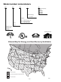
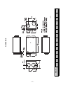
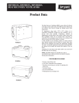
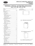
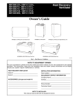
HRVBBLHU HRVBBSVC HRVBBLVU SINGLE-PACKAGE ELECTRIC HEATING COOLING UNITS Heat Recovery Ventilators The Heat Recovery Ventilation (HRV) system offered by Bryant is the finest unit on the market today. The HRVB provides efficient and cost-effective heat recovery during the heating season when needed most. As temperatures drop below 23°F (–5°C), indoor air is recirculated periodically through the heat exchanger core to prevent frost from forming. Competitors’ methods of supplementary electric defrost waste energy. Unlike rotary wheel heat exchangers which mix air streams, these cross flow or counterflow heat exchangers ensure that there is no mixing of the stale air stream with the fresh outdoor air stream. HRVBBLHU A filter installed on the incoming outdoor air stream removes large airborne particles from the intake air stream before they enter the heat exchanger and reduces the maintenance required. The units’ acoustically engineered design makes them the quietest on the market and ensures that comfort is felt, not heard. Unlatching 2 suitcase style latches allows easy removal of the filters and core for cleaning. FEATURES • Energy saving defrost cycle • Cross flow, counterflow heat exchangers • Two filters on incoming outdoor air stream to protect the HRV core • Acoustical design • No-tools maintenance • Polypropylene heat exchanger core HRVBBSVC HRVBBLVU Form No. PDS HRV.71.1 Model number nomenclature HRV BB LHU 1 150 Maximum Capacity (CFM) 150 CFM 200 CFM 250 CFM 330 CFM Electrical Supply: 1 — 115 volts Descriptor: LHU — Large Horizontal Unit SVU — Small Vertical Unit LVU — Large Vertical Unit Brand: Bryant Equipment Type: Heat Recovery Ventilator TESTED/CERTIFIED HOME VENTILATING INSTITUTE DIVISION OF AMCA Climate Map for Energy and Heat Recovery Ventilators Edmonton Vancouver Calgary Regina Timmins Helena Salem Winnipeg Bismark Montreal Green Bay Boise Syracuse Ottawa Milwaukee Minneapolis Boston Hartford Madison Des Moines Sacramento Salt Lake City Denver Topeka Oklahoma City Springfield Chicago Detroit Indianapolis Harrisburg Washington D.C. Raleigh Nashville Atlanta Columbia Honolulu Austin Baton Rouge Orlando HRV Recommended ERV Recommended w/HRV or ERV Wall Control ERV Recommended A00099 —2— Controls and accessories part no. nomenclature K V B CN 01 01 BAU CONTROL DESCRIPTION BAU — Bryant Automatic Control BBS — Bryant Basic Control BST — Bryant Standard Control ACCESSORY DESCRIPTION 6FM — 6 in. Flowmeters (2) 7FM — 7 in. Flowmeters (2) 8FM — 8 in. Flowmeters (2) EXH — Exhaust Hood HOD — Intake Hood KIT — Balancing Kit FIR — Interlock Relay TIMER DESCRIPTION 20C — 20-Minute Timer Kit Carrier 60M — 60 Minute Adjustable Timer Kit FILTER DESCRIPTION 112 — 11-1/2 x 12-3/4 116 — 11-7/8 x 16-5/8 123 — 12-15/16 x 13-1/2 145 — 14-3/8 x 15-1/2 713 — 7-13/16 x 13-1/2 810 — 8-1/8 x 10-3/4 812 — 8-7/8 x 12-3/4 916 — 9 x 16-5/8 01 — Single Pack 01 — Part Number AC CN FL TM — Accessory — Control — Filter Media — Timer A — Original Series B — Second Series V — Heat Recovery Ventilator (HRV) K — Accessory Kit ACCESSORIES Kit Number KVBCN0101CBS KVBCN0101CST KVBCN0101CAU KVAAC0101FIR KVATM010120C KVATM010160M KVAAC0101HOD KVAAC0101KIT KVAAC01016FM KVAAC01017FM KVAAC01018FM KVAFK0101150 KVAFK0201200 KVAFL0101713 KVAFL0101123 KVAFL0101123 KVAFL0101145 KVAFL0101810 KVAFL0101145 KVAFL0101810 Description Basic HRV Control Standard HRV Control Automatic HRV Control Interlock Relay 20 Minute Push Button Timer 60 Minute Timer Exterior Intake and Exhaust Hood Start up Balancing Kit 6 in. Flow Meter Collar 7 in. Flow Meter Collar 8 in. Flow Meter Collar Internal Filter Internal Filter Internal Filter Internal Filter Internal Filter Internal Filter Internal Filter Internal Filter Internal Filter Where Used Used with all HRVs Used with all HRVs HRVBLSVU, HRVBBLVU When combining an HRV with a Furnace or Fan Coil Used with all HRVs when 20 minute manual operation is required Used with all HRVs, time is adjustable between 10 and 60 minutes 2 Required Start up Balancing Kit, includes (2) 6 in. Flow Meter Collars & Magnehelic Gage At start up, when 6 in. duct work is connected to HRV At start up, when 7 in. duct work is connected to HRV At start up, when 8 in. duct work is connected to HRV Used with HRVBBLHU 1150 Unit 11 3/4 x 12 7/8 x 3/4 (2) Used with HRVBBLHU 1250 Unit 11 3/4 x 16 3/4 x 3/4 (2) Used with HRVBBSVU 1150 Unit 7 13/16 x 13 1/2 (2) Used with HRVBBSVU 1200 Unit 12 15/16 x 13 1/2 (2) Used with HRVBBLVU 1200 Unit 12 15/16 x 13 1/2 (2) Used with HRVBBLVU 1200 Unit 14 3/8 x 15 1/2 Used with HRVBBLVU 1330 Unit 8 1/8 x 10 3/4 (1) Used with HRVBBLVU 1330 Unit 14 3/8 x 15 1/2 (1) Used with HRVBBLVU 1200 Unit 8 1/8 x 10 3/4 (1) —3— CONTROL FEATURES Basic Control: Allows the user to manually set fan speed to low or high as required to maximize comfort. Standard Control: Offers automatic dehumidistat control and the option to select continuous or intermittent fan operation. Setting the wall control to low will activate the continuous mode. Automatic Control: In addition to the features found with standard control, this package offers a recirculation mode. These controls may only be used to operate stand-alone units with the defrost option which enables the recirculation feature. CONTROL DESCRIPTION FAN SPEED CONTROL DEHUMIDISTAT CONTROL CONTINUOUS MODE* INTERMITTENT MODE* CIRCULATION MODE† Basic Yes No Yes No No Standard Yes Yes Yes Yes No Automatic‡ Yes Yes Yes Yes Yes * Air exchange with outside. † No air exchange with outside. ‡ Use only on units with defrost. CONTROL DESCRIPTION AND USAGE Fan Speed Control — Enables user to modulate fan speed from low to high air exchange with outside. Dehumidistat Control — Allows the user to select the relative humidity level at which the unit would change fan speed for dehumidification in the winter months. Continuous Mode — If the relative humidity inside the building is lower than selected, air exchange occurs with the outside at low speed. If the relative humidity inside the house is higher than selected, air exchange occurs with the outside at high speed. Ensures continuous air exchange for constant air quality. Intermittent Mode — If the relative humidity inside the building is lower than selected, no air exchange occurs and the system turns off. If the relative humidity inside the house is higher than selected, air exchange occurs with the outside at high speed. Ensures minimum air exchange level when the building is unoccupied to minimize operating costs. Circulation Mode — If the relative humidity inside the building is lower than selected, the ambient air would be circulated and filtered at high speed. If the relative humidity inside the house is higher than selected, air exchange would occur with the outside at high speed. Ensures continuous movement and filtration of air for maximum comfort. Available with automatic control only. AUTOMATIC DEFROST CYCLE FEATURES All models offer a non-electric defrost cycle feature which prevents frost and ice buildup within the heat recovery core. When the outside air temperature falls below 23°F (–5°C) it is electronically sensed and the dampers close the outside air ports. This allows warm indoor air to recirculate within the heat recovery core. The frequency of this cycle increases as the outside air temperature decreases. 23°F TO 55°F (–5°C TO –15°C) 4°F TO –17°F (–15.6°C TO –27.3°C) BELOW –18°F (–27.8°C) MODEL DEFROST* EXCHANGE† DEFROST* EXCHANGE† DEFROST* EXCHANGE† HRVBBLHU 6 Minutes 60 Minutes 6 Minutes 32 Minutes 6 Minutes 20 Minutes HRVBBSVU 6 Minutes 60 Minutes 6 Minutes 32 Minutes 6 Minutes 20 Minutes HRVBBLVU 6 Minutes 60 Minutes 6 Minutes 32 Minutes 6 Minutes 20 Minutes * All defrost times are in the standard mode (as shipped) † Time between defrost when within specified temperature range —4— —5— 15-1/8 19 HRVBBLHU1150 HRVBBLHU1250 A B in. C MODEL NO. D A 483 384.2 mm 43/4 " (120.6) 5-13/16 4-1/16 in. B 20" (508.0) 23/16" (56.2) 4 PLCS 147.7 104 mm 4 5-1/16 5/58 in. 1" (25.4) 2 PLCS C 128.1 143.3 mm 301/4" (768.3) 2 14-1/2 14-1/2 in. DIMENSIONS D 3 1 368.9 368.9 mm G E F 15" (381.0) 57/8" DIA (149.2) 4 PLCS 11-3/16 10-3/8 in. E 283.9 288.9 mm 4-3/8 4-3/8 in. F 111.3 111.3 mm A98002 NOTES: 1.FRESH AIR FROM OUTSIDE 2.FRESH AIR FROM HRV TO HOUSE 3.STALE AIR FROM HOUSE TO HRV 4.STALE AIR FROM HR TO OUTSIDE 167/8" (428.6) 181/8" (460.4) 25/16" (58.7) 10-1/16 7-3/4 in. G mm 255.6 196.9 —6— in. 18-1/2 24-1/2 MODEL NO. HRVBBSVU1150 HRVBBSVU1200 A 622.2 469.9 mm in. 8-3/16 4-11/16 A B C 208.0 119.1 mm 1″ [25.4] 2 PLCS 4 5 3⁄4″ [146.0] 1 B in. 19-5/16 13-5/16 4 9⁄16″ [115.9)] C 19 3⁄4″ [501.7] 490.6 388.2 mm G 15 11⁄16″ [398.5] 22 1/16″ [560.4] D 3 in. E 14-9/16 D 369.9 392.1 mm DRAINS 11⁄16″ DIA. [17.5] 2 PLCS 2 3⁄16″ [55.6] 4 PLCS 3 3⁄16″ [81.0] F DIA 2 PLCS 27″ [685.8] 1 15⁄16″ [23.8] 15-7/16 5 7⁄8″ DIA [149.2] 2 PLCS DIMENSIONS (continued) 16-15/16 13-9/16 in. E 430.2 344.5 mm 6-7/8 5-7/8 in. NOTES: 1. FRESH AIR FROM OUTSIDE TO HRV 2. FRESH AIR FROM HRV TO HOUSE 3. STALE AIR FROM HOUSE TO HRV 4. STALE AIR FROM HRV TO OUTSIDE 2 WALL CONTROL WIRING 3⁄8″ DIA [9.5] POWER CORD F mm 174.6 149.2 A98003 19-15/16 19-15/16 in. G mm 506.2 506.2 —7— 24 1⁄16″ [611.2] 1 1⁄2″ [38.1] 2 PLCS 4 7 3⁄16″ [182.6] 23 15⁄16″ [608.0] 1 ″ [25.4] 2 PLCS 18 5⁄16″ [465.1] 17 9⁄16″ [446.9] 12 3⁄4″ [323.9] 2 3⁄16″ [55.6] 2 PLCS 1 4 3⁄4″ [120.6] [17.5] 2 PLCS 11⁄16″DIA. DRAIN 6 15⁄16″ [176.2] 15 1⁄2″ [393.7] 5 13⁄16″ [147.6] 3 22 3⁄8″ [568.3] 41″ [1041.4] 7 1⁄8″ [181.0] 2. FRESH AIR FROM HRV TO HOUSE 3. STALE AIR FROM HOUSE TO HRV 4. STALE AIR FROM HRV TO OUTSIDE WALL CONTROL WIRING 3⁄8″ DIA [9.5] POWER CORD NOTES: 1. FRESH AIR FROM OUTSIDE TO HRV HRVBBLVU1200 or HRVBBLVU1330 19 1⁄16″ [484.2] 8 3⁄16″ [208.0] 43″ (1092.2) 5 7⁄8″ DIA [148.2] 2 PLCS 8 1⁄8″ DIA [206.4] 2 PLCS 2 DIMENSIONS (continued) A98001 PHYSICAL DATA MODEL DESCRIPTION Model No. Port Locations Core Type Weight — lb (kg) CONVENTIONAL COMPACT HIGH EFFICIENCY HRVBBVHU1150 HRVBBVHU1260 HRVBBSVC1150 HRVBBSVC1200 HRUBBLVU1150 HRUBBLVU1200 HRUBBLVU1330 Sides Sides Top Top Top Top Top Polypropylene Cross Flow Polypropylene Cross Flow Polypropylene Cross Flow Polypropylene Cross Flow Polypropylene Cross Flow Polypropylene Counterflow Polypropylene Counterflow 65 (29.5) 73 (33.2) 60 (27) 80 (36.3) 80 (36.3) 120 (54.5) 120 (54.5) Shipping Weight — lb (kg) 75 (34) 83 (37.6) 75 (34) 89 (40.4) 89 (40.4) 143 (64.9) 143 (64.9) Shipping Dimensions (in.) Height Width Depth 23 1/16 36 1/16 17 13/16 22 15/16 35 1/16 22 5/16 31.5 23.25 26.00 31.5 23.25 26.00 31.5 23.25 26.00 47.5 26.0 26.0 47.5 26.0 26.0 PERFORMANCE DATA MODEL DESCRIPTION Model No. CONVENTIONAL COMPACT HIGH EFFICIENCY HRVBBLHU1150 HRVBBLHU1250 HRVBBSVC1150 HRVBBSVC1200 HRVBBLVU1150 HRVBBLVU1200 HRVBBLVU1330 Capacity — CFM @ 0.5– 0.3ESP (in. wc) 130–168 191–210 106–150 177–211 123–141 189–209 300–334 Efficiency (Sensible) — percent 32°F (0°C) –13°F (–25°C) 65 65 65 60 69 60 77 67 81 69 84 72 80 74 Efficiency (Latent) — percent @ all temperatures Heat Core Exchange Area — cu ft (cu m) 0 0 0 0 0 0 0 120 3.4 166 4.7 90 8.4 144 13.3 144 13.3 210 19.5 210 19.5 ELECTRICAL DATA CONVENTIONAL Model COMPACT HIGH EFFICIENCY HRVBBLHU1150 HRVBBLHU1250 HRVBBSVC1150 HRVBBSVC1200 HRVBBLVU1150 HRVBBLVU1200 HRVBBLVU1330 Voltage 120 120 120 120 120 120 120 Max Power — watts 150 218 115 195 115 250 500 Max Amps 1.4 1.9 1.2 1.8 1.2 2.2 5.4 —8— METHODS TO SIZE HRV’S METHOD 1 1. Calculate cu ft of occupied space. 2. Multiply by recommended air changes per hr (AC/h). 3. Divide by 60 minutes per hr to convert to CFM. EXAMPLE: 2000 sq ft with 8 ft ceiling 0.35 air changes per hr (AC/h) (2000 sq ft x 8 ft ceiling x 0.35 AC/h) / 60 min/h = 93.3 CFM METHOD 2 1. Multiply number of people times 15 CFM/person. 2. Multiply number of bath rooms 20 CFM/each. 3. Add 25 CFM for kitchen. EXAMPLE: 2 people 2 baths 1 kitchen (2 x 15) + (2 x 20) + 25 = 95 CFM ADDITIONAL HEATING AND COOLING LOAD CHARTS Although the ventilators process the outside air before it enters the home, additional heating and cooling loads need to be considered. HEATING LOAD BTU Outside Temp °F –25 –20 –15 –10 –5 0 5 10 15 20 25 30 35 40 Heat Load (Btuh) @ Inside Design Temp 72°F HRVBBLHU1150 HRVBBSVC1250 HRVBBSVC1150 HRVBBSVC1200 HRVBBLVU1150 4,688 8,165 6,970 7,690 5,500 4,466 7,744 6,470 7,090 5,030 4,598 8,008 5,990 6,520 4,590 4,334 7,547 5,520 5,970 4,160 4,069 7,087 5,070 5,440 3,750 3,805 6,627 4,550 4,840 3,300 3,541 6,167 4,130 4,360 2,940 3,502 6,100 3,730 3,900 2,600 3,220 5,608 3,290 3,400 2,240 2,938 5,116 2,930 3,000 1,940 2,950 5,138 2,580 2,610 1,670 2,636 4,591 2,240 2,250 1,410 2,322 4,045 1,900 1,880 1,160 2,009 3,498 1,600 1,560 1,940 HRVBBLVU1200 6,650 6,070 5,510 4,970 4,470 3,910 3,470 3,050 2,600 2,240 1,910 1,600 1,300 1,040 HRVBBLVU1330 9,990 9,310 8,650 8,000 7,380 6,640 6,060 5,500 4,870 4,350 3,850 3,370 2,870 2,430 The heating load chart shows the heating loads in Btuh for a range of winter design temperatures for each model of ventilator. EXAMPLE: The heating design temperature for Milwaukee, WI is –4°F. At –5°F, the additional heating load of the HRVBBLHU1250 is 8417 Btuh. This additional load should be taken into consideration when sizing the heating equipment. —9— COOLING LOAD BTU Outside Enthalpy Btu/lb 30 31 32 33 34 35 36 37 38 39 40 41 42 Cooling Load (Btuh) @ Inside Design Temp 75°F and 50% Relative Humidity HRVBBLHU1150 HRVBBLHU1250 HRVBBSVC1150 HRVBBSVC1200 670 1,071 780 990 1,090 1,741 1,300 1,650 1,509 2,411 1,820 2,310 1,928 3,080 2,340 2,970 2,347 3,750 2,860 3,630 2,766 4,419 3,380 4,290 3,185 5,089 3,910 4,950 3,604 5,759 4,430 5,610 4,023 6,428 4,950 6,270 4,442 7,098 5,470 6,930 4,861 7,767 5,990 7,590 5,280 8,437 6,510 8,250 5,699 9,107 7,030 8,910 HRVBBLVU1150 770 1,290 1,800 2,310 2,830 3,340 3,860 4,370 4,890 5,400 5,910 6,430 6,940 HRVBBLVU1200 990 1,650 2,310 2,970 3,630 4,290 4,950 5,610 6,270 6,930 7,590 8,250 8,910 HRVBBLVU1330 1,390 2,310 3,240 4,170 5,090 6,020 6,940 7,870 8,790 9,720 10,650 11,570 12,500 The cooling load chart shows loads in Btuh as well. To use the cooling load chart, first find the design enthalpy from a psychrometric chart using the design dry bulb and wet bulb temperatures. (See psychrometric chart on p. 11.) The cooling load can then be found for a range of enthalpies for each ventilator. EXAMPLE: The cooling design dry bulb temperature for Milwaukee, WI is 87°F and the average wet bulb at that temperature is 73°F. On the psychrometric chart the enthalpy is about 37.7 Btu/lb of dry air which will round up to 38 Btu/lb of dry air. In the left column, at 38 Btu/lb the HRVBBLHU1250 would have an additional cooling load of 6428 Btuh. This additional load should be taken into account when sizing the air cooling equipment. —10— Dry Bulb Temperature F Wet Bulb, Dewpoint or Saturation Temperature F 30 20% 40% 60% 35 18 17 Btu 19 40 . 45 tu 4B Btu +0 .3 +0 50 u Bt 55 29 28 26 .5 +0 t 25 24 45 50 55 7 8 9 31 60 33 34 2 30 60 37 65 u 32 36 35 65 Bt -.0 38 70 -. 41 40 39 u Bt 04 23 22 21 20 Btu 40 2 +0. Below 32˚F, properties and enthalpy deviation lines are for ice. 25 12 80% 16 15 14 13 12 11 10 20 25 1 +0. t 30 35 cu f 12.5 27 cu f 13.0 70 75 tu 43 44 45 46 % 8 8B 42 u Bt 6 -.0 0% R 49 t 90 -.0 48 ive m % 80 % 30 10% 85 20% 85 U 90 90 95 95 Enthalpy at saturation, Btu per pound of dry air 40 80 % 50 % ity 60 Hu 47 75 ela t % 70 cu f BT -.01 PSYCHROMETRIC CHART t id 13.5 100 100 105 105 0 10 20 30 40 50 60 70 80 90 100 110 120 130 140 150 160 170 180 Grains of moisture per pound of dry air air -0.3 Btu of dry per pound Enthalpy de viation Btu BTU -.02 cu f 14.0 110 0 .95 .85 .90 .80 .75 .70 .65 .60 .55 .50 .45 .40 Sensible heat factor A98394 .001 .002 .003 .004 .005 .006 .007 .008 .009 .010 .011 .012 .013 .014 .015 .016 .017 .018 .019 .020 .021 .022 .023 .024 .025 .35 Pounds of moisture per pound of dry air y air f dr nd o pou per cu ft 14.5 —11— HRV INSTALLED WITH FORCED AIR SYSTEM A99297 HRV INSTALLED WITH INDEPENDENT AIR DISTRIBUTION A99298 SPECIFICATIONS SUBJECT TO CHANGE WITHOUT NOTICE UNIT MUST BE INSTALLED IN ACCORDANCE WITH INSTALLATION INSTRUCTIONS Cancels: New FORM PDS HRV.71.1 © 2000 Bryant Heating & Cooling Systems, 7310 W. Morris St., Indpls., IN 46231 —12— PRINTED IN U.S.A. Catalog No. 12HR-VBO 3-00