1
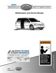
4-
"RAUN,-ILLENNIUM3ERIES&ULLY!UTOMATIC7HEELCHAIR,IFTS
:$51,1*
,
#ONSUMER
7HEELCHAIR,IFTS
0ROVIDING!CCESSTOTHE7ORLD
)NTERNATIONAL#ORPORATE(DQRS0/"OX7INAMAC).53!
4(%,)&4&!8
*ANUARY
¤
¤
2SH
UD
0DQ WRU
XD V
O
5HDGPDQXDO
EHIRUHRSHUDWLQJ
OLIW)DLOXUHWRGR
VRPD\UHVXOWLQ
VHULRXVERGLO\
LQMXU\DQGRU
SURSHUW\GDPDJH
.HHSPDQXDOLQ
OLIWVWRUDJHSRXFK
0ATENT0ATENT0ATENTS0ENDING
3ERIES
,
3ERIES,
/PERATORgS-ANUAL
3ERIES /PERATORgS-ANUAL
/PERATORgS-ANUALFOR
Congratulations
We at The Braun Corporation wish to express our fullest appreciation
on your new purchase. With you in mind, our skilled craftsmen have designed and assembled the finest lift available.
This manual includes safety precautions, lift operating instructions,
manual operating instructions, and instructions for maintenance and lubrication procedures.
Your lift is built for dependability, and will bring you years of pleasure
and independence, as long as maintenance is performed regularly and the lift
is operated by an instructed person.
Sincerely,
THE BRAUN CORPORATION
Ralph W. Braun
Chief Executive Officer
Contents
Lift Terminology
Roll Stop Latch ............................................... 18
Lift Terminology Illustration .................................... 2
Latch Operation ........................................ 18, 19
Introduction ............................................................ 3
Bridging .......................................................... 19
Direction ................................................................. 3
Handrails ........................................................ 19
Lift Components ................................................... 3-5
Lift Passengers
Lift Actions and Functions ................................... 5, 6
Passenger Orientation (Boarding Direction) ... 20
Lift Operation Safety
Vehicle (Floor Level) Loading and
Safety Symbols ...................................................... 7
Unloading ....................................................... 20
Lift Operation Safety Precautions ...................... 8-11
Wheelchair-equipped Occupant Seat Belts .......... 21
Pre-Lift Operation Notes and Details
Operation Procedure Review .......................... 21, 22
General Safety ................................................ 12, 13
Preventive Maintenance .................................. 22, 23
Lift Control Switches ....................................... 13, 14
Lift Operating Instructions ............................ 24-30
Lift Features
Manual Operating Instructions ..................... 31-33
Bridge Plate ................................................... 15
Decals and Antiskid ...................................... 34, 35
Automatic Floor Level Switching .................... 15
Maintenance and Lubrication ...................... 36, 37
Automatic Roll Stops ................................. 16-18
Warranty and Registration Instructions ...... 38, 39
Page 1
Top Parallel Arms (2)
Towers (2)
Module-mounted
Control Switches
Opposite Pump Side Cylinder
Adjustable Quiet-Ride Bumper
THE
P.O.
BRA
BOX
310UN
219CO
MOD
WINARPO
946EL
L955
6153
MAC
RAT
SERI U31
IN
ION
AL
4248
01.0
NUM
4699
PATE133.
BER
6
NT 28.1
4CB
DOM
1099
Bridge Plate
Unfold Assist Compression Springs (2)
Opposite Pump Side Vertical Arm
Base Plate
Vertical Arm Covers (4)
Handrail-mounted Up/Down Switch
Bridge Plate
Extension
Pump Side
Cylinder
TM
Pump
Module
(Rear)
Lift Terminology
Illustration
Roll Stop Cylinder
(not visible -underside of platform)
Handrails (2)
L955U: Roll stop cylinder
and latch are on opposite
side of platform.
Bottom Parallel
Arms (2)
Roll Stop Latch
Rotating Pivot
Slide Arms (2)
Platform
Platform Pivot Arms (2)
Pump Side Vertical Arm
Inboard
Left (Rear)
Right (Front)
Outboard
Platform Side Plates (2)
Side Entry Roll Stop (L955SE only)
Page 2
Automatic Roll Stop (ARS)
Lift Terminology
Introduction:
Braun L955 Millennium Series
lifts are consumer oriented
(designed to allow operation by
the wheelchair passenger). L955
lift models provide fully automatic
operation of all lift functions as
well as optional automatic door
operators (if so equipped).
The L955 Millennium Lift Series
includes variations of L955SE
and L955U lift models. Lift model
numbers indicate platform/roll
stop configuration and physical
dimensions. A standard L955SE
lift model is depicted in the Lift
Terminology Illustration. The
bridge plate extension is bolted to
the bridge plate (as shipped). In
stepwell applications where
additional platform length is
required, the extension plate may
be bolted to the heel (inboard
end) of the platform.
Lift operation procedures are
identical for all L955 Series lift
models. The operating Instructions contained in this manual
and appearing on lift-posted
operating instructions decals
address the lift control switches
and the corresponding lift functions. Instructions are provided
for manual operation of the lift in
event of power or equipment
failure.
Terminology: Become familiar
with the terminology that will be
used throughout this manual.
Become familiar with the identification of lift components and their
functions. Contact your lift sales
representative or call The Braun
Corporation at 1-800-THE LIFT if
any of this information is not fully
understood.
Direction: The terms "left (rear),"
"right (front)," "inboard," and
"outboard" will be used throughout this manual to indicate
direction (as viewed from outside
the vehicle looking directly at the
lift). Refer to the Lift Terminology
Illustration for clarification of
direction terms.
Lift Components
Refer to the Lift Terminology
Illustration for identification of lift
components.
Pump Module: The lift-mounted
Page 3
Lift Terminology
pump module consists of the
hydraulic pump, the manual hand
pump and electrical components
that power the lift electric/hydraulic systems.
Module-mounted Control
Switches: The pump module is
equipped with three color-coded
and function-labeled control
switches (OPEN/CLOSE, IN/OUT
and UP/DOWN). The switches
activate the automatic lift functions and optional door operators.
Further details are provided in the
Lift Pre-Lift Operation section
(page 13).
Lift Frame: The lift frame
consists of the base plate, two
towers, the parallel arms, the
vertical arms, platform pivot arms
and the handrails. The two main
Page 4
hydraulic cylinders are housed in
the parallel arms. The electrical/
hydraulic powered lift frame
components mechanically unfold,
lower, raise and fold the lift
platform assembly.
Bridge Plate: The bridge plate
assembly consists of the bridge
plate (striker back) and the bridge
plate extension (flap). The hinged
bridge plate assembly bridges the
gap between the lift platform and
the vehicle floor when the platform
is positioned at floor level. Note:
The bridge plate extension (flap) is
bolted to the bridge plate (as
shipped) in the Lift Terminology
Illustration. In stepwell applications where additional platform
length is required, the extension
plate may be bolted to the heel
(inboard end) of the platform.
Dual Handrails: Dual handrails
are provided for wheelchair
passenger use. The handrails
automatically unfold to the
deployed position when the
platform unfolds and fold automatically to the stowed position
when the platform folds. The
passenger may choose to grip the
handrails when on the lift platform
(if applicable). Note: An additional UP/DOWN control switch is
built into the right (front) handrail.
Platform Assembly: The lift
platform assembly consists of the
steel tubing frame with grating
surface upon which the wheelchair is positioned, the outboard
roll stop, roll stop latch, the side
entry roll stop (SE only), and the
hydraulic cylinder assembly that
powers the outboard roll stop.
Lift Terminology
Automatic Roll Stop(s):
L955SE and L955U lift platforms
are equipped with a cylinderpowered outboard roll stop that
provides a ramp for wheelchair
loading and unloading at ground
level. L955SE platforms are
equipped with an outboard roll
stop and a side entry roll stop.
The side entry roll stop is useful in
tight parking situations by reducing
wheelchair caster “turn-out” when
boarding and exiting the platform.
The two roll stops function together in unison.
Roll Stop Latch: The springloaded latch locks the outboard
roll stop in the vertical position
when the platform raises above
ground level.
Manual Operation System: A
manual backup hand pump is
built into the pump module. The
lift platform can be unfolded,
lowered, raised and folded using
the hand pump. Manual Operation Instructions are provided on
pages 31-33.
Lift Actions and Functions
UNFOLD (Out) - Platform
Unfold: Unfold is the action of
the platform rotating out and
down from the fully-stowed
(vertical) position to floor level
(horizontal) position when the
UNFOLD switch is pressed.
DOWN - Platform Lower: Down
is the action of the platform
lowering from floor level position
to fully-lowered (ground level)
position when the DOWN switch
is pressed.
DOWN - Roll Stop Unfold
(Deploy) - When the platform
reaches the fully-lowered
(ground) position and the DOWN
switch is continued to be
pressed, the outboard roll stop
and the side entry roll stop rotate
downward from vertical position
to ramp position.
UP - Roll Stop Fold (Raise):
When the lift is fully lowered and
the roll stops are in the ramp
position, pressing the UP switch
first rotates the roll stops upward
from ramp position to vertical
position.
UP - Platform Raise: Up is the
action of the platform raising
Page 5
Lift Terminology
from ground level to floor level
(fully-raised) position when the
UP switch is pressed.
unfolding from the stowed
position and when raising from
ground level.
FOLD (In) - Platform Fold: Fold
is the action of the platform
rotating up and in from the floor
level (horizontal) position to fullystowed (vertical) position when
the FOLD switch is pressed.
Note: Further details regarding
lift control switches and the
corresponding lift functions are
provided in the Pre-Lift Operation
Notes and Details section.
Stowed Position: The lift is
stowed when the lift platform has
been fully raised and folded fully
(vertical position).
Floor Level: Floor level is the
position (height) the platform
assembly reaches in order for
the wheelchair passenger to
enter and exit the vehicle (fully
raised). The platform automatically stops at floor level when
Page 6
Lift Operation Safety
Safety Symbols
SAFETY FIRST!
Know That ...
All information contained
in this manual and
supplements (if included), is
provided for your safety. Familiarity with proper operation
instructions as well as proper
maintenance procedures are
necessary to ensure safe,
troublefree operation. Safety
precautions are provided to
identify potentially hazardous
situations and provide instruction
on how to avoid them.
A
D
B
WARNING
This symbol indicates
important safety
information regarding
a potentially hazardous situation that
could result in serious
bodily injury and/or
property damage.
C
CAUTION
This symbol indicates
important information
regarding how to
avoid a hazardous
situation that could
result in minor personal injury or property damage.
Note: Additional information provided to help clarify or detail a specific subject.
These symbols will appear throughout this manual as well as on the labels posted on your lift. Recognize
the seriousness of this information.
Page 7
Lift Operation Safety
Lift Operation Safety Precautions
WARNING
If the lift operating
instructions, manual
operating instructions
and/or lift operation
safety precautions are
not fully understood,
contact The Braun
Corporation immediately. Failure to do so
may result in serious
bodily injury and/or
property damage.
WARNING
Read manual and supplement(s) before operating lift. Read
and become familiar with all safety precautions, pre-lift
operation notes and details, operating instructions and
manual operating instructions before operating the lift. Note:
Wheelchair passengers and all transit agency personnel
(drivers and wheelchair lift attendants) must read and
become familiar with the contents of this manual and
supplement(s) before operation.
WARNING
Load and unload on level surface only.
WARNING
Engage vehicle parking brake before operating lift.
WARNING
Provide adequate clearance outside the vehicle to accommodate the lift before opening lift door(s) or operating lift.
WARNING Inspect lift before operation. Do not operate lift if you suspect lift damage, wear or any
abnormal condition.
WARNING Keep operator and bystanders clear of area in which the lift operates.
Page 8
Lift Operation Safety
WARNING Whenever a wheelchair passenger (or standee) is on the platform, the:
• Passenger must be positioned fully inside yellow boundaries
• Wheelchair brakes must be locked
• Roll stops must be up (vertical)
• Roll stop latch must be fully engaged
• Passenger should grip both handrails (if able).
WARNING Load and unload clear of vehicular traffic.
WARNING Do not overload or abuse. The load rating applies to both the raising and lowering functions
- continuous lifting capacity is 800 lbs.
WARNING Do not operate or board the lift if you or your lift operator are intoxicated.
WARNING Do not raise front wheelchair wheels (pull wheelie) when loading (boarding) the platform.
WARNING Open lift door(s) fully and secure before operating lift.
WARNING Position and secure (buckle, engage, fasten, etc.) the wheelchair-equipped occupant seat
belt (torso restraint) before loading onto the wheelchair lift platform.
WARNING Lift attendants must ensure that lift occupants keep hands, arms and all other body parts
within the lift occupant area and clear of moving parts.
Page 9
Lift Operation Safety
Lift Operation Safety Precautions
WARNING
If the lift operating
instructions, manual
operating instructions
and/or lift operation
safety precautions are
not fully understood,
contact The Braun
Corporation immediately. Failure to do so
may result in serious
bodily injury and/or
property damage.
WARNING Platform must be positioned at floor level (bridge plate
height) when loading or unloading in and out of vehicle.
WARNING Do not use platform roll stops as a barrier (brake). Stop and
brake wheelchair when loading onto the platform (manually
stop and brake manual wheelchairs — stop powered wheelchairs with the wheelchair controls).
WARNING Turn powered (electric) wheelchairs off when on lift platform.
WARNING Press the DOWN switch until the entire platform rests on
ground level (lowered fully) and the outboard roll stop is fully
unfolded (ramp position) before loading or unloading a
passenger at ground level.
WARNING Outboard platform roll stops must be fully unfolded (ramp
position) until the entire wheelchair crosses roll stops when
loading or unloading at ground level.
WARNING Accidental activation of control switch(es) may cause unintended operation(s).
Page 10
Lift Operation Safety
WARNING Maintenance and lubrication procedures must be performed as specified in this manual by
authorized (certified) service personnel.
WARNING Replace missing, worn or illegible decals.
WARNING Keep this operator's manual in lift-mounted manual storage pouch when not in use.
WARNING Never modify (alter) a Braun Corporation lift.
WARNING Do not use accessory devices not authorized by The Braun Corporation.
WARNING Do not remove any guards or covers.
WARNING Keep clear of any hydraulic leak.
WARNING Failure to follow these safety precautions may result in serious bodily injury and/or property damage.
Page 11
Pre-Lift Operation Notes and Details
WARNING
Read and become
familiar with all lift
operation safety
precautions, pre-lift
operation notes and
details, operating
instructions and
manual operating
instructions prior to
operating the lift. If
this information is not
fully understood,
contact The Braun
Corporation immediately. Failure to do so
may result in serious
bodily injury and/or
property damage.
Page 12
Braun L955 Millennium Series lifts
are consumer oriented (designed to
allow operation by the wheelchair
passenger). L955 Series lifts are
typically installed in vehicles
equipped with fully-automatic door
operators. The L955 provides fully
automatic operation of all lift functions as well as optional automatic
door operators (if so equipped).
Note: An attendant must manually
open and close lift door(s) in applications where power door
operator(s) are not provided.
operating instructions and manual
operating instructions before attempting lift operating procedures.
It is the responsibility of the lift
operator (attendant and/or wheelchair passenger) to properly activate
all power (lift and door) functions.
General Safety: Before operating
the lift, always engage the vehicle
transmission in Park “P” and engage
the vehicle parking brake. Lift
operators (attendants), wheelchair
passengers and bystanders must
keep clear of the area in which the
power doors (if equipped), and the lift
Read and become familiar with all lift
operation safety precautions, pre-lift
operation notes and details, lift
Become familiar with all lift features
and the proper operation of the lift
components before attempting lift
operation. Refer to the Lift Terminology section for identification of and
desrciption of lift components.
Contact The Braun Corporation
immediately if any of this information
is not fully understood. Call 1-800THE LIFT.
Pre-Lift Operation Notes and Details
operates (clear of all moving
parts). The lift occupant (passenger) must keep hands, arms and
all other body parts within the lift
occupant area and clear of
moving parts. Follow all lift
operation and wheelchair passenger information detailed in this
manual.
Control Switches
Pump Module Control
Switches: The lift-mounted
WARNING
Discontinue lift use
immediately if any lift
component does not
operate properly.
Failure to do so may
result in serious
bodily injury and/or
property damage.
control switches are color-coded
and function-labeled to correspond to the color coding and
switch-function labels that appear
on the lift operating instructions
decal. Triangular-shaped colorcoded symbols (
) appear on
the lift operating instructions
decal. The color of the symbol
corresponds to the color of the
switch to be used. The direction
(point) of the symbol corresponds
with the direction the switch
should be activated (pressed) to
produce the intended lift function.
Press switches upward
for these functions:
Door(s)
Platform
CLOSE
IN (Fold)
UP
Yellow
Orange
Red
Yellow
Orange
Red
OPEN
Door(s)
OUT
(Unfold)
DOWN
Platform
Press switches downward
for these functions:
Page 13
Pre-Lift Operation Notes and Details
Control Switches (continued)
Handrail UP/DOWN Switch: A
spring-loaded horizontal-slide
style switch is built in the right
(front) handrail. The handrail UP/
DOWN switch activates the
platform and the roll stops (same
as pump-mounted UP/DOWN
switch). Slide the switch knob out
DOWN
UP
to the UP position to raise the
platform. Slide the knob in to the
DOWN position to lower the
platform.
Auxiliary Control Switches: A
six-touch remote control system,
a third station control, a handheld control and an outside
control station are available as
options. All auxiliary controls
activate lift functions and automatic door operators except the
hand-held control. The handheld control activates lift functions only.
Do not press lift-mounted
switches and auxiliary control
station switches at the same
time. Do not attempt to interface
after-market control systems.
Page 14
Braun Corporation Aftermarket Control Systems
Policy:
The Braun Corporation
manufactures dedicated
control systems for its
products. These control
systems have been designed and tested for use in
conjunction with specific
Braun products. Braun
control systems are the only
control systems authorized
for use with Braun products.
Do not attempt to interface
aftermarket control systems
with Braun products. To do
so may result in serious
bodily injury and/or property damage.
Pre-Lift Operation Notes and Details
Lift Features
Bridge Plate: The hinged bridge
plate assembly bridges the gap
between the lift platform and the
vehicle floor when the platform is
positioned at floor level. The
bridge plate assembly consists of
the bridge plate and the bridge
plate extension.
Fully-Unfolded (horizontal)
Bridge Plate (bridging position)
Typically, the bridge plate
extension is bolted to the
bridge plate as shown in the Lift
Terminology Illustration (standard bridge plate configuration). In stepwell applications
where additional platform
length is required, the extension plate may be bolted to the
heel (inboard end) of the
platform.
bridge plate folds (rotates) to the
vertical position.
When the OUT (Unfold) switch
is pressed and the platform
unfolds from stow position to
floor level, the bridge plate is
automatically deployed to the
bridging (horizontal) position.
When the IN (Fold) switch is
pressed and the platform folds
from deployed (horizontal)
position to stowed position, the
Automatic Floor Level Switching: When the platform unfolds
from the stowed position, the
platform stops automatically at
floor level when fully unfolded.
When raising the platform from
ground level, the platform automatically stops at floor level when
raised fully.
The outboard edge of the bridge
plate extension rests on the lift
platform (standard bridge plate
configuration). When the
extension plate is bolted to the
heel of the platform, the bridge
plate rests on the extension
plate.
Page 15
Pre-Lift Operation Notes and Details
Lift Features (continued)
Although the L955 features
automatic floor level switching,
the lift operator (wheelchair
passenger or attendant), must
view the platform to be certain
the platform is properly positioned at vehicle floor level and
WARNING
Discontinue lift use
immediately if any lift
component does not
operate properly.
Failure to do so may
result in serious
bodily injury and/or
property damage.
Page 16
the bridge plate is properly
positioned when a passenger
is entering or exiting the
vehicle. If the lift platform does
not automatically stop at floor
level as outlined, discontinue
lift operation immediately.
Automatic Roll Stops: The
L955SE platform is equipped
with an outboard roll stop and
a side entry roll stop (L955U lift
models are not equipped with a
side entry roll stop). See
photos A, B and C. Both
cylinder-powered roll stops
provide a ramp for wheelchair
loading and unloading at
ground level. The side entry
roll stop is useful in tight
parking situations by reducing
wheelchair caster “turn-out”
when boarding and exiting the
platform. The two roll stops
function in unison. Details
follow. Discontinue lift operation immediately if either roll
stop does not operate properly.
Belt-operated Side Entry Roll Stop
(L955SE models only)
A
Aluminum Extruded Outboard Roll Stop
Pre-Lift Operation Notes and Details
Outboard Roll Stop: When the
platform lowers fully to ground
level, the roll stop cylinder
compression spring automatically unfolds (rotates) the roll
stop to the ramp position (fully
unfolded). See photos A and B.
Although the outboard roll stop
is lift-powered, the activation of
the roll stop is controlled by the
lift operator. Activating either
DOWN switch unfolds the roll
stop. The roll stop is cylinderpowered to automatically fold
(rotate) to the vertical position
when the UP switch is activated
(roll stop raises before platform
raises).
Fully-Unfolded (Ramp position) Roll Stops
B
Side Entry Roll Stop: When
the platform lowers fully to
ground level, the spring-loaded
side entry roll stop unfolds
(rotates) to the ramp position
simultaneously with the outboard roll stop (when DOWN
switch is activated). See photos
A and B. The belt and chain
Fully-Engaged Roll Stop Latch
Disengaged
Roll Stop
Latch
Fully-Folded
(Up-vertical)
Roll Stops
C
L955U: The roll stop
latch is on opposite
side of the platform.
Note: The platform must raise
approximately two inches
before the latch engages fully.
2"
Latch Foot
Page 17
Pre-Lift Operation Notes and Details
Lift Features (continued)
driven roll stop is powered by
the roll stop cylinder to automatically fold (rotate) to the
vertical position when the UP
switch is activated.
WARNING
Discontinue lift use
immediately if any lift
component does not
operate properly.
Failure to do so may
result in serious
bodily injury and/or
property damage.
Page 18
Roll Stop Latch: A springloaded latch engages the
outboard roll stop when the
roll stop rotates upward from
ramp position to the vertical
position (UP switch is activated to raise the platform
above ground level).
roll stop).
Outboard Roll Stop and Roll
Stop Latch Operation: The lift
Note: The platform must
raise approximately two
inches before the latch
engages fully (see photo C on
17). L955U: The roll stop latch
and roll stop cylinder are on the
opposite (left) side of platform.
The latch disengages the roll
stop when the platform lowers
fully (reaches ground level)
and the latch foot contacts the
ground (latch raises above the
The lift operator or attendant must
be certain the entire platform
reaches and rests safely on the
ground.
Pre-Lift Operation Notes and Details
operator must activate the
DOWN switch to lower the
platform fully to the ground. The
lift operator or attendant must
view the platform as it lowers to
be certain the entire platform
reaches and rests safely on the
ground. Stop activating the
DOWN switch if any portion of
the platform is obstructed while
descending or the platform does
not reach ground level for any
reason (contact with an obstruction, mechanical failure, exceeding the lift “floor-to-ground”
capacity, etc.).
After the platform is fully lowered
(platform reaches the ground),
the lift operator should continue
to press the DOWN switch to
unfold the outboard roll stop and
the side entry roll stop fully
(ramp position). Note: The roll
stops must be fully unfolded
until the entire wheelchair has
crossed the roll stops when
loading or unloading at ground
level. Discontinue lift operation immediately if the roll
stops or latch do not operate
properly.
Handrails: Dual handrails are
provided for wheelchair passenger (or standee) use. The
handrails automatically unfold to
the deployed position when the
platform unfolds and fold automatically to the stowed position
when the platform folds. The
passenger may choose to grip
the handrails when on the lift
platform (if applicable).
Bridging: The L955SE incorporates a bridging feature. This
feature stops the down travel of
the platform if the outboard end
of the platform contacts a raised
surface (such as a curb), preventing the operator from lowering the inboard end of the
platform.
Note: The right (front) handrail
is equipped with an UP/DOWN
control switch (details in Control
Switches section). Discontinue
lift operation immediately if
the handrails do not operate
properly.
Page 19
Pre-Lift Operation Notes and Details
Lift Passengers
Do not attempt to load or unload
a passenger in a wheelchair or
other apparatus that does not fit
on the platform area. Do not
exceed the 800 pound load
capacity of the lift.
Passenger Orientation (Boarding Direction): The wheelchair
passenger must face outward
whenever on the platform.
The passenger must be positioned in the center of the
platform to prevent side-to-side
load imbalance. Other persons
should not ride on the platform
with the wheelchair passenger.
The wheelchair brakes must be
locked, the roll stops must be in
Page 20
the fully-up (vertical) position and
the outboard roll stop latch must
be fully engaged whenever a
wheelchair passenger is on the
platform.
Do not use the outboard roll stop
as a barrier (brake). Stop and
brake the wheelchair when fully
loaded on the platform. Manually
stop and brake manual wheelchairs. Stop powered wheelchairs with the wheelchair controls. Turn powered (electric)
wheelchairs off when on the
platform.
Vehicle (Floor Level) Loading
and Unloading: The platform
must be fully raised (at floor
level) and the bridge plate must
be properly positioned when
loading or unloading a passenger
in or out of the vehicle. Although
the L955 features automatic floor
level switching, it is the responsibility of the lift operator to
ensure the platform and the
bridge plate are properly
positioned at floor level when
loading and unloading passengers.
If the roll stops, bridge plate,
handrails or any other lift component does not operate as outlined
in this manual, discontinue lift
use immediately and contact
your sales representative or call
The Braun Corporation at 1-800THE LIFT. One of our national
Product Support representatives
will direct you to an authorized
service technician who will
inspect your lift.
Pre-Lift Operation Notes and Details
Wheelchair-Equipped Occupant Seat Belts
The Braun Corporation recommends wheelchair passengers
position and buckle their wheel-
chair-equipped seat belt (torso
restraint) as specified by the
manufacture before loading onto
a wheelchair lift.
WARNING
Different types of disabilities
require different types of wheelchairs and different types of
wheelchair-equipped occupant
restraint belt systems (torso
restraint). It is the responsibility
of the wheelchair passenger to
have his or her wheelchair
equipped with an occupant
restraint (seat belt) under the
direction of their health care
professional.
Position and secure
(buckle, engage,
fasten, etc.) the
wheelchair-equipped
occupant seat belt
before loading onto
the wheelchair lift
platform. Failure to
do so may result in
serious bodily injury
and/or property
damage.
Wheelchair lift attendants should
be instructed on any special
needs and/or procedures required
for safe transport of wheelchair
passengers.
Operation Procedure Review
The Braun Corporation recommends that the wheelchair lift
user and/or attendant review the
safety precautions and operation
procedures appearing in this
manual and on lift-posted decals
with your wheelchair lift sales
representative, before attempting
lift operation. Any questions or
concerns can be answered by
your sales representative at that
time.
Using your own wheelchair,
operate the lift through all
functions and enter and exit the
Page 21
Pre-Lift Operation Notes and Details
vehicle with the sales
representative on hand to
ensure the lift is right for you
as the end user (applicable
for your use based on your
physical abilities and the
physical characteristics of
your personal wheelchair).
Become familiar with the
proper operation of your lift
before operating the lift by
yourself.
This lift operator’s manual
must be stored in the liftmounted manual storage
pouch when not in use.
Page 22
Preventive Maintenance
Regular preventive maintenance
will reduce potential lift operation downtime and increase the
service life of the lift, as well as
enhancing safety.
• Do the automatic door(s) open
fully (if equipped)?
• Does the lift safely clear the
door(s) when unfolding and
folding?
• Do the lift control switches
function properly?
• Do the automatic roll stops
operate properly?
• Does the roll stop latch operate properly?
• Do the handrails fuction
properly?
• Is the power source adequate
or weak?
During routine inspections,
operate the lift through a minimum of one complete cycle and
note the following:
Exposure to harsh weather
elements, environment conditions, or heavy usage, etc. may
require more frequent mainte
Maintenance is necessary to
ensure safe and trouble-free lift
operation. Preventive lift
maintenance consisting of
careful inspections of your lift
system and cleaning the lift
should be a part of your routine.
Simple inspections can detect
potential lift operational problems.
Pre-Lift Operation Notes and Details
nance and lubrication procedures.
Preventive maintenance visual
inspections do not take the
WARNING
place of the procedures specified in the Maintenance and
Lubrication Schedule provided
in the applicable lift installation
and service manual. Refer to
the Maintenance and Lubrication section in this manual for
further details.
Maintenance and
lubrication procedures must be performed by authorized
service personnel as
specified in the
applicable installation/service manual.
Failure to do so may
result in serious
bodily injury and/or
property damage.
Page 23
Lift Operating Instructions
WARNING
Read and become
familiar with all lift
operation safety
precautions, pre-lift
operation notes and
details, operating
instructions and
manual operating
instructions prior to
operating the lift. If
this information is not
fully understood,
contact The Braun
Corporation immediately. Failure to do so
may result in serious
bodily injury and/or
property damage.
Page 24
WARNING
Whenever a
passenger is on the
platform, the:
• Passenger must
face outward
• Wheelchair brakes
must be locked
• Roll stops must be
UP
Failure to do so may
result in serious
bodily injury and/or
property damage.
Before lift operation, park the
vehicle on a level surface, away
from vehicular traffic. Place the
vehicle itransmission in “Park”
and engage the parking brake.
Photos appearing in the Lift
Operating Instructions depict lift
functions being activated by liftmounted control switches only.
Lift-posted Warnings and Lift
Operating Instructions decal
24069 provides lift operating
instructions. Replace any
missing, worn or illegible
decals.
Follow the Manual Operating
Instructions provided on pages
31-33 in event of power or
equipment failure.
Lift Operating Instructions
A
To Open Door(s):
B
Automatic Door Operator(s):
Press yellow OPEN switch until
door(s) are fully open. Release
switch.
Manual Door(s):
Manually open door(s) fully and
secure.
To Unfold Platform (Out):
Press orange OUT switch until
platform stops (unfolds fully –
reaches floor level). Release
switch.
C
D
Page 25
Lift Operating Instructions
To Unload Passenger:
E
F
1. Read notes below! Load passenger onto platform facing outward
and lock wheelchair brakes.
Note: Roll stops must be UP and
roll stop latch must be fully engaged before loading passenger
onto platform. Lower head to
clear vehicle door jamb header.
DOWN
G
Page 26
2. Press red DOWN switch until the
entire platform reaches ground
level (stops) and roll stop unfolds
fully (see Photos H and I). Release switch.
Handrail Switch: Slide knob in to
DOWN position. See Photo G.
H
Lift Operating Instructions
I
To Unload Passenger: (continued)
J
3. Unlock wheelchair brakes and
unload passenger from platform.
Note: Roll stops must be fully
unfolded (ramp position) until the
entire wheelchair has crossed the
roll stop. See Photos K and L.
K
L
Page 27
Lift Operating Instructions
To Load Passenger:
M
N
1. Load passenger onto platform
facing outward and lock wheelchair brakes.
Note: Roll stops must be fully
unfolded (ramp position) until the
entire wheelchair has crossed the
roll stop. See Photos K and L.
2. Press red UP switch until platform
stops (reaches floor level). Release switch.
UP
O
Page 28
Handrail Switch: Slide knob out to
UP position.
Note: Roll stops must be UP and
roll stop latch must be fully engaged before raising platform.
Platform will raise above ground
level approximately two inches
before latch engages fully.
P
approximately 2"
Lift Operating Instructions
Q
To Load Passenger (continued):
R
3. Unlock wheelchair brakes and load
passenger from platform into
vehicle. Note: Lower head to
clear door jamb header.
To Fold Platform (In):
Press orange IN switch until
platform stops (fully folded).
Release switch.
S
T
Page 29
Lift Operating Instructions
U
To Close Door(s):
Automatic Door Operator(s):
Press yellow CLOSE switch until
door(s) are fully closed. Release
switch.
Manual Door(s):
Manually close door(s) fully.
Page 30
Manual Operating Instructions
If you experience power or equipment failure, refer to the Manual
Operating Instructions to operate
the lift. Instructions and photos are
provided for all steps that differ
from standard lift operation procedures. Manual Instructions Decal
27146 (posted on pump cover)
provides manual operating instructions also. Refer to the Lift Operat-
ing Instructions for all normal lift
operation procedures (such as
loading and unloading passengers).
Follow all Lift Operation Safety
Precautions!
(OUT):
Press OUT switch
until platform stops
(reaches floor level).
TO UNLOAD PASSENGER:
Release Valve
1. Load passenger onto
platform facing outward
and lock wheelchair
brakes.
2. Press DOWN switch
until platform stops and
roll stop unfolds fully.
3. Unlock wheelchair
brakes and unload
passenger from platform.
TO LOAD PASSENGER:
1. Load passenger onto
platform facing outward
and lock wheelchair
brakes.
2. Press UP switch until
platform stops
(reaches floor level).
3. Unlock wheelchair
brakes and unload
passenger from platform.
TO FOLD PLATFORM (IN):
approximate
1/16" intervals
Press IN switch until
platform stops.
TO CLOSE DOOR(S):
WARNING
Press CLOSE switch
until door(s) are fully
closed.
Contact The Braun
Corporation before
adjusting hydraulic
pressure relief
valve. Failure to
do so may result
in serious bodily
injury and/or
property damage.
24069
maximum
30 inch lbs
22249
Valve Tightening
Specification:
Once valve seats
(stops), tighten 15
to 30 inch pounds
as shown.
minimum
15 inch lbs
seats
(stops)
1. TO UNFOLD PLATFORM (OUT):
Using hand pump handle:
a. Open hand pump valve
counterclockwise (open 1/2 turn only)
until platform reaches floor level.
b. Close hand pump valve clockwise.
2. DOWN (TO LOWER):
Use hand pump handle to open (turn)
hand pump valve counterclockwise
(open 1/2 turn only).
TO LOAD PASSENGER:
1. UP (TO RAISE):
Using hand pump handle:
a. Close hand pump valve clockwise.
b. Insert handle in pump and stroke until
platform reaches floor level.
2. TO FOLD PLATFORM (IN):
OSE
CL
HAND PUMP
VALVE
Close valve
before operating
electric pump.
OPEN
Insert handle in pump and stroke.
19448
Microswitch Adjustment Instructions
Unfold/Down (Top) Microswitch
Turn adjustment bolt counterclockwise
to stop platform unfold function sooner.
Turn adjustment bolt clockwise to allow
platform to unfold further.
Up/Fold (Bottom) Microswitch
Turn adjustment bolt clockwise to stop
platform raise function sooner. Turn
adjustment bolt counterclockwise to allow
platform to raise further.
24242
A
Note: Close backup
pump release valve
securely before operating
electric pump.
OPEN
HAND PUMP
TO UNLOAD PASSENGER:
OSE
CL
MANUAL
INSTRUCTIONS
Release Valve
Page 31
Manual Operating Instructions
Refer to photos and illustration of
release valve on previous page.
To Unfold Platform (Out):
Using hand pump handle (Photo B):
Hand
Pump
Handle
and turn counterclockwise (open
— 1/2 turn only) until the platform
reaches ground level and/or roll
stop unfolds.
a. Place slotted end of pump handle
onto back-up pump release valve
and turn counterclockwise
(open — 1/2 turn only) until the
platform reaches floor level
(fully unfolded). See Photo C.
b. Turn the release valve clockwise
(close) to stop the platform. See
Photo C.
Note: Valve must be tight, but do
not overtighten.
Open
Close
(Down)
(Up/Stop)
• To Lower Platform:
DOWN • To Unfold Roll Stop:
B
Page 32
Place slotted end of pump handle
onto back-up pump release valve
C
Manual Operating Instructions
Refer to photos and illustration of
release valve on page 31.
UP
• To Fold Roll Stop:
• To Raise Platform:
Note: Close back-up pump release
valve securely before operating
electric pump.
Using hand pump handle:
a. Place slotted end of pump handle
onto back-up pump release valve
and turn clockwise to close
securely. See Photo D.
Note: Valve must be tight, but do
not overtighten.
Open
Close
(Down)
(Up/Stop)
b. Insert handle into back-up pump
and stroke until platform reaches
floor level (see Photo E).
To Fold Platform (In):
Insert handle into back-up pump and
stroke until platform stops (folds
fully). See Photo E.
D
E
Page 33
Decals and Antiskid
Decals
WARNING
26701
24242
Unfold/Down (Top) Microswitch
Turn adjustment bolt counterclockwise
to stop platform unfold function sooner.
Turn adjustment bolt clockwise to allow
platform to unfold further.
25675
Page 34
Whenever a wheelchair
passenger is on the
platform, the:
• Passenger must face
outward
• Wheelchair brakes must
be locked
• Roll stop must be up
Failure to follow these
rules may result in
serious bodily injury
and/or property damage.
Parking Courtesy
Requested
TM
"Providing Access to the World"
International Corporate Hdqrs: P.O. Box 310 Winamac, IN 46996 USA
1-800-THE LIFT
(219) 946-6153
FAX: (219) 946-4670
Fairfield, NJ USA
Oslo, Norway
TO UNFOLD PLATFORM
(OUT):
Press OUT switch
until platform stops
(reaches floor level).
TO UNLOAD PASSENGER:
1. Load passenger onto
platform facing outward
and lock wheelchair
brakes.
2. Press DOWN switch
until platform stops and
roll stop unfolds fully.
3. Unlock wheelchair
brakes and unload
passenger from platform.
1. Load passenger onto
platform facing outward
and lock wheelchair
brakes.
2. Press UP switch until
platform stops
(reaches floor level).
3. Unlock wheelchair
brakes and unload
passenger from platform.
Contact The Braun
Corporation before
adjusting hydraulic
pressure relief
valve. Failure to
do so may result
in serious bodily
injury and/or
property damage.
Clearwater, FL USA
Kitchener, Ontario Can.
Huntington Beach, CA USA
Rocklea, Queensland Aust.
12375
27146
Press OPEN switch
until door(s) are fully
open.
TO LOAD PASSENGER:
WARNING
WARNING
WARNING
• Read manual before
operating lift.
• Load and unload on level
surface only.
• Engage vehicle parking
brake before operating lift.
• Provide adequate clearance
outside of vehicle to
accommodate lift.
• Do not operate lift if you
suspect lift damage, wear
or any abnormal condition.
• Keep operator and
bystanders clear of area
in which lift operates.
TO FOLD PLATFORM (IN):
Press IN switch until
platform stops.
MANUAL
OPERATION
OSE
CL
Up/Fold (Bottom) Microswitch
Turn adjustment bolt clockwise to stop
platform raise function sooner. Turn
adjustment bolt counterclockwise to allow
platform to raise further.
24242
22249
Lift installation and servicing prohibited by
anyone who has not been certified by The Braun
Corporation Sales and Service School. Certified
service technicians should call 1-800-THE LIFT
to receive applicable installation/service manual.
Failure to follow this policy may result in serious
bodily injury and/or property damage.
12375
TO OPEN DOOR(S)
Microswitch Adjustment Instructions
25652
25675
24069
LIFT OPERATING
INSTRUCTIONS
UP
DOWN
17866
OPEN
Note: Clean surfaces as
detailed on opposite page
before posting decals.
The lift is only as safe as
the operator. Replace any
missing, worn or illegible
decals! Part numbers are
provided for decals. Inspect
your lift for missing, worn or
illegible decals. Call 1-800THE LIFT for replacements.
26701
Replace missing, worn
or illegible decals.
Failure to do so may
result in serious bodily
injury and/or property
damage.
OPEN
CLOSE
Using hand pump handle:
TO UNFOLD PLATFORM (OUT):
1. Close hand pump valve (turn clockwise).
2. Insert handle in pump and stroke until
platform folds fully (stops).
3. Open hand pump valve (turn
counterclockwise) until platform reaches
floor level. Open 1/2 turn only.
4. Close hand pump valve (turn clockwise).
DOWN (TO LOWER):
Open hand pump valve (turn
counterclockwise). Open 1/2 turn only.
UP (TO RAISE):
1. Close hand pump valve (turn clockwise).
2. Insert handle in pump and stroke until
platform reaches floor level.
TO FOLD PLATFORM (IN):
TO CLOSE DOOR(S):
Insert handle in pump and stroke.
Press CLOSE switch
until door(s) are fully
closed.
22249
25652
24069
Close valve before operating electric pump.
27146
25580
Decals and Antiskid
25580 (actual size: 1-1/2" x 24")
Antiskid
Inspect your lift for any
missing or worn antiskid.
Order as needed.
WARNING
Replace missing or
worn antiskid.
Failure to do so may
result in serious
bodily injury and/or
property damage.
Note: Clean surfaces
with isopropyl alcohol
before decal or antiskid
application. Use a clean
cloth or paper towels.
Do not use oily shop
rags. Wipe surface free
of residue with dry
portion of cleaning cloth.
Available Antiskid
Size
Color
Part No.
2" x 12"
2" x 12"
3" x 12"
3" x 12"
Black
Yellow
Black
Yellow
#24172-BK
#24172-YL
#24173-BK
#24173-YL
6" x 12"
6" x 12"
Black
Yellow
#24174-BK
#24174-YL
Page 35
Maintenance and Lubrication
Maintenance is necessary to
ensure safe and trouble-free lift
operation. General preventive
maintenance consisting of
inspections of your lift system and
cleaning the lift should be a part
of your routine.
The L955 has been designed with
many self-lubricating components. Lubricate the pivot points
specified on page 37 approximately every four weeks (or 100
cycles) with a light penetrating
type oil (30 weight or equivalent).
Severe conditions (weather,
environment, heavy usage, etc.)
may require more frequent
lubrication.
Preventive maintenance visual
inspections and lubrication
procedures do not take the place
Page 36
of the procedures specified in the
Maintenance and Lubrication
Schedule provided in the applicable lift installation and service
manual. The procedures outlined
in the Maintenance and Lubrication Schedule must be performed at the recommended
scheduled intervals by an
authorized Braun Corporation
service representative who has
attended and been certified by
The Braun Corporation Sales
and Service School.
If the scheduled maintenance and
lubrication procedures are not
being performed, or if there is any
sign of lift damage, wear, abnormal condition or improper operation, discontinue lift use immediately. Contact your sales
representative or call The Braun
Corporation at 1-800-THE LIFT.
One of our national Product
Support representatives will direct
you to an authorized service
technician who will inspect your
lift.
WARNING
Maintenance and
lubrication procedures must be performed by authorized
service personnel as
specified in the
applicable installation/service manual.
Failure to do so may
result in serious
bodily injury and/or
property damage.
Bridge Plate
Pivot Points
(2 places)
THE
P.O.
BR
BOX
AU
310 N
219
CO
MOD
-946WIN
RP
EL
L95
AMA OR
-615
SER 5U3
3 C ATI
IN
142
IAL
ON
01.0 NUM 48
4699
PATE133
BER
6
NT .28.
14C
B
DOM
1099
Maintenance and Lubrication
TM
Note: LPS2 General
Purpose Penetrating Oil
is available in eleven
ounce aerosol cans from
The Braun Corporation
(part number 15807).
Note: Clean lubrication
points before applying
lubricants.
Roll Stop Latch
(pivot and slide points)
Rotating Pivot
Slide Arm Pivot Pins
(2 places - behind cover)
Platform Fold Axles
(2 places)
Platform Pivot Pin
(2 places)
Side Entry Roll Stop
Hinge (4 places)
Note: Disregard references
to components not present.
Page 37
Warranty and Registration Instructions
Immediately upon receiving your
lift, examine the unit for any
damage. Notify the carrier at
once with any claims.
Two warranty/registration cards
(shown below) are located in the
lift-mounted owner’s manual
storage pouch. The sales representative must process one of the
cards. The consumer must fill out
the other card and mail it to The
Braun Corporation. The warranty
is provided on the back cover of
this manual. The warranty cards
must be processed to activate
the warranty.
The Braun Serial No./Series No.
identification tag (shown below) is
located on the opposite pump
side tower. This I.D. tag contains
the product identification information provided on the Warranty/
Registration card. Record the
information in the space provided
on the next page. This information must be provided when
filing a warranty claim or
ordering parts.
The Braun Corporation
Series No.
Pump Code
Model No.
Serial No.
Cylinder Code
PO Box 310
Winamac, IN 46996
(574) 946-6153
LIFT MODEL #
OWNER'S WARRANTY REGISTRATION
L955SE314248
L955SE314248-A4-04293-35-14CF
SERIAL NUMBER
A4-04293
PURCHASED FROM
OWNER
DATE INSTALLED
NAME
CYLINDER
35
14CF
MFG DATE
ADDRESS
1/12/2003
CITY
TELEPHONE
PUMP CODE
PATENTS PENDING-5,261,779-5,806,632
STATE
ZIP
TO VALIDATE WARRANTY
REGISTRATION CARDS MUST BE RETURNED TO THE BRAUN CORPORATION.
Sample Warranty/Registration Card
Page 38
Sample Serial No./Series No. Identification Tag
Warranty and Registration Instructions
Model No.
Pump Code
Series No.
Cylinder Code
Serial No.
Date of Manufacture
Note: Retain this information
for future use. You must have
this information when filing a
warranty claim or ordering
Page 39
"Providing Access to the World"
®
Over 300 Braun
Dealers Worldwide
"RAUNh7ORRY&REEv
4HREE9EAR,IMITED7ARRANTY
3ERIES
,
3ERIES,
4HE"RAUN#ORPORATIONOF7INAMAC)NDIANAWARRANTSITSWHEELCHAIRLIFTAGAINST
DEFECTSINMATERIALANDWORKMANSHIPFORTHREEYEARSPROVIDINGTHELIFTISOPERATEDAND
MAINTAINEDPROPERLYANDINCONFORMITYWITHTHISMANUAL4HISWARRANTYISLIMITEDTOTHE
ORIGINALPURCHASERANDDOESNOTCOVERDEFECTSINTHEMOTORVEHICLEONWHICHITISINSTALLED
ORDEFECTSINTHELIFTCAUSEDBYADEFECTINANYPARTOFTHEMOTORVEHICLE
4HISWARRANTYCOMMENCESONTHEDATETHELIFTISPUTINSERVICEPROVIDINGTHE
WARRANTYREGISTRATIONCARDISCOMPLETEDANDRECEIVEDBY4HE"RAUN#ORPORATIONWITHIN
DAYSOFPURCHASE
4HISWARRANTYALSOCOVERSTHECOSTOFLABORFORTHEREPAIRORREPLACEMENTOFMOST
PARTSFORONEYEARWHENPERFORMEDBYANAUTHORIZED"RAUN2EPRESENTATIVE!"RAUNLABOR
SCHEDULEDETERMINESCOSTALLOWANCEFORREPAIRS
4HISWARRANTYDOESNOTCOVERNORMALMAINTENANCESERVICEORPERIODICADJUSTMENTS
NECESSITATEDBYUSEORWEAR4HE"RAUN#ORPORATIONWILLNOTUNDERANYCIRCUMSTANCESPAY
FORLOSSOFUSEOFLIFTORVEHICLEINWHICHITISINSTALLEDORLOSSOFTIME
4HISWARRANTYWILLBECOMENULLANDVOIDIFTHELIFTHASBEENDAMAGEDTHROUGH
ACCIDENTMISUSEORNEGLECTORIFTHELIFTHASBEENALTEREDINANYRESPECT
!LLILLUSTRATIONSDESCRIPTIONSANDSPECIFICATIONSINTHISMANUALAREBASEDONTHELATESTPRODUCTINFORMATIONAVAILABLE
ATTHETIMEOFPUBLICATION4HE"RAUN#ORPORATIONRESERVESTHERIGHTTOMAKECHANGESATANYTIMEWITHOUTNOTICE
*ANUARY0ATENT0ATENT0ATENTS0ENDING©4HE"RAUN#ORPORATION
/PERATORgS-ANUAL
/PERATORgS-ANUAL
4-
"RAUN,-ILLENNIUM3ERIES&ULLY!UTOMATIC7HEELCHAIR,IFTS
0$'(,1
$0(5,&$