1
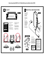
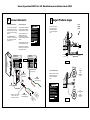
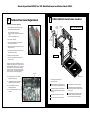
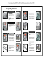
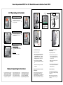
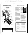
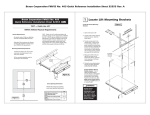
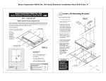
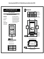
Braun Corporation FMVSS No. 403 Quick Reference Installation Sheet 32494
Braun Corporation FMVSS No. 403
Quick Reference Installation Sheet 32494
1 Position Lift
Installation Kits
“DOT — Private Use Lift”
Standard Length Chassis
NHTSA Vehicle Physical Requirements
Nonmodified OEM full
size floors meet all
requirements.
Alternative floor
structures are allowed
providing the installed lift
system passes all FMVSS 403 requirements.
Side Door
Rear Door
GM/Chevy
30958K
*30959K
Ford
“DOT - Private Use Lift” verifies this
platform lift meets only the “private use lift”
requirements of FMVSS No. 403. This lift
may be installed on all vehicles appropriate
for the size and weight of the lift, except for
buses, school buses, and multi-purpose
passenger vehicles other than motor homes
with a gross vehicle weight rating (GVWR)
that exceeds 4,536 kg (10,000 lb).
OEM (Van) Chassis
Floor Requirements
Vehicle
30956K
30957K
Align
(Parallel)
Vertical Arm
must clear
door opening.
B
Installation Kit
30955K supplied
in lift parts box.
Detailed instructions
supplied in kits.
Extended
Length
Chassis
Rear Door
30970K-42
* Rear Bumper
Replacement Kit
19395A96 required.
*30981K
Align
(Parallel)
Vertical Arm
must clear
door opening.
Center lift in
door opening.
A
90
Side to Side Alignment
Figure B
C
Inboard Edge of Threshold Warning (Top) Plate
(with plate folded down)
Figure A
Door Opening Dimensions
Minimum per
Vehicle lift access door opening
must meet specified dimensions.
A
Minimum Clear Door
Opening Height
18" FMVSS No. 403 18"
NVL955IB3144
47"
B
Clear Door Opening Width
40"
C
Maximum Floor-to-Ground
42"
Figure C
Edge of Finished Floor or Stepwell Filler
(not outboard edge of vehicle)
Lift towers and
vertical arms must
be parallel (aligned)
with vertical sides
of door jamb and
perpendicular (90˚)
to the vehicle floor.
Braun Corporation FMVSS No. 403 Quick Reference Installation Sheet 32494
2 Secure Lift
3 Attach Power and Ground Cables
Figure D
4
1
7
1. Drill 1-1/8" diameter
grommet access
hole. Check under
the vehicle for
obstructions.
6
Note. All fasteners must meet
FMVSS 571.403 Section 6.3.
2
3
5
1. Drill two mounting holes
(holes 6 and 7).
WARNING
Check for obstructions such as gas
lines, wires, exhaust,
etc. before drilling
or cutting. Failure to
do so may result in
serious bodily injury
and/or property
damage.
2. Insert grommet.
Secure grommet
with two self-tap
screws.
8
5. Tighten mounting bolts per
sequence detailed above.
Note deflection detail below.
3. Manually deploy lift and
check lift clearance. Drill
remaining mounting holes.
ble y
Ca Sentr
y
r
tte it
Ba Circu
to
3. Route ground
and power cables
through grommet.
Route cables clear
of exhaust, other
hot areas and
moving parts.
4. Install below floor mounting
hardware per instructions
supplied in kit.
2. Temporarily secure lift
using two mounting bolts
(holes 6 and 7).
Figure F
Star Washer
4. Connect ground
and power cables.
Mounting Bolt Torque
Target: 30 foot pounds.
Power
Feed Stud
Floor
Grommet
Rubber
Boot
Ground Cable Mounting
®
®
29823
®
9/32" Diameter
Pilot Hole
29823
Dimensions
MUST
be Equal
29823
90
Ground Cables
is
s
has
90
C
Figure E
To Correct:
TIG
H T EN
Tighten
OSEN
LO
Loosen
3/8" Hex Nut
To Correct:
TIG
H T EN
Tighten
OSE N
LO
HTEN
TIG
OSEN
LO
Loosen
TIG
H T EN
Tighten
OSEN
LO
Loosen
5/16"
External Tooth
Star Washer
Figure G
5/16-18 x 3/4"
Thread Cutting
Screw
Pump mounted ground
cable must be routed
and mounted directly to a
vehicle framing member.
Failure to do so will
void warranty of certain
electrical components.
CAUTION
Position and secure
ground cable clear
of lift operation.
Gr
to ound
Ch C
as abl
sis e
Ground Cable Corrosion:
When mounting ground
cables, remove undercoating, dirt, rust, etc. from
framing member around
mounting holes (minimum
5/8” diameter area). Apply protective coating to
mounting holes to prevent
corrosion. Failure to do
so will void warranty of
certain electrical components.
Braun Corporation FMVSS No. 403 Quick Reference Installation Sheet 32494
4 Connect Interlocks
5 Adjust Platform Angle
Vehicle and Lift Interlocks
Optional Interlock Kits
The pump module is equipped
with a lift interface 9-circuit connector (female socket). A mating
9-circuit connector (male plug) is
supplied.
Universal Interlock Kit 30940K is
available for easy interface with
vehicle OEM electronic signals.
To meet minimum NHTSA
requirements, connect to vehicle
interlock harness as outlined
below (Steps 1-5)
WARNING
Install and verify
proper operation of
all NHTSA mandated
interlocks as
specified. Failure
to do so will result
in a non-compliant
installation and may
result in serious
bodily injury and/or
property damage.
Instrument Panel Display Kit
30938K provides an LED
Panel Display that interfaces
with Braun Universal Interlock Kit
30940K.
Detailed installation instructions
are supplied with interlock kits.
Angle A
equals
Angle B.
Adjustments to platform
angle may be required
if base plate wedges
are used. See Figures I
and J.
✓
A
Note: All Braun Corporation interlocks require a positive (+12V)
Lift Stowed signal (Pin 7).
Wedges
B
PUMP MODULE
CONNECTOR - J21
INTERLOCK
CONNECTOR - P21
9-COND WIRE CODE
9-COND WIRE CODE
NO.
1
2
Lif
t
Pu
m
Mo p
du
le
3
4
5
6
NOT USED
2
3
4
5
6
7
8
9
Figure H
NO.
1
NOT USED
NOT USED
VEHICLE SECURE (INPUT)
7
LIFT STOWED (+12V)
LIFT STOWED (GND)
NOT USED
SIGNAL DEFINITION
NOT USED
As ed
p
hip
S
NOT USED
4
5
6
NOT USED
VEHICLE SECURE (INPUT)
7
LIFT STOWED (+12V)
9
LIFT STOWED (GND)
NOT USED
8
1
5
4
9
8
7
Disconnect
and remove
eye terminal
HTEN
TIG
Floor Level Positioning:
3
Install 31798A
in cavity 7 (+) or 9 (-)
Connect
To
In
Connect vehicle
interlock signal wires
ck
lo
r
te
Manufacturer’s Part Numbers
Connector: AMP 172169
Terminal:TYCO 770904-3
Outboard
Reset floor level positioning
if wedges are used. See
Floor Level Adjustment
panel.
Turn
clockwise
to
raise
outboard end
of platform
WARNING
Disconnect
4
Inboard
Figure I
3 2 1
6 5 4
9 8 7
Note: Pins 7 and 9
300mA maximum.
1
5
2
2
6
NOT USED
3
1 2 3
4 5 6
7 8 9
3
NOT USED
2
NOT USED
NOT USED
9
8
1
SIGNAL DEFINITION
Approximately
1” Clearance
LIF
T
(Ye
llo SIG STO
w/L NA WE
igh L
D
VE
HIC
tB
lue
LE
S
)
(Gr IGN SEC
ey/ AL UR
Re
E
d)
Reset floor level
position as specified
in Floor Level
Adjustment Instructions if wedges are
used. Failure to do so
may result in serious
bodily injury and/or
property damage.
OSEN
LO
Figure J
Turn
counterclockwise
to
lower
outboard end
of platform
Braun Corporation FMVSS No. 403 Quick Reference Installation Sheet 32494
6 Platform Floor Level Adjustment
7
FMVSS 403/404 Certification Checklist
Platform Floor Level Position Adjustment:
UP
UNFOLD
FOLD
1. Position platform at desired floor level position
(passenger loading/unloading height).
DOWN
Audible
Threshold
Warning
Threshold
Area
DOT — Private Use Lift
Note: Position platform such that:
a. the inner roll stop is laying flat on the threshold
plate
b. platforrm has not begun to fold
2. Turn Lift Power switch Off.
Lift Ready
Green LED
3. Press Floor Level Set button (located between
pump housing and lift tower).
4. While pressing the Floor Level Set button, turn the
Lift Power switch On.
Inboard
Locator
5. Continue pressing the Floor Level Set button until
the lift sounds three “beeps.”
6. Release the Floor Level Set button.
Floor Level Set Button
Figure K
Platform
7. Cycle lift to verify that platform stops at the set
floor level position.
Diagnostic codes have been established in event the
lift platform floor position does not set (the lift does not
sound three “beeps” - see Step 5 above). The control
board located inside the pump housing is equipped
with an LCD screen. Remove the pump cover to access the LCD screen. The following diagnostic codes
will help resolve floor position setting problems:
91 – The platform position is out of a predetermined acceptable range
92 – The Bridge Microswitch is not activated
(adjust switch or lower the platform)
94 – The Outer Barrier Up switch is not
activated (adjust switch)
95 – The Outer Barrier Latched sensor is not
activated.
Inboard
Platform
Outboard
Platform
LCD Screen
Outer Barrier
The following operations must be
functionally verified.
Vehicle movement is prevented unless the
lift door is closed, ensuring the lift is stowed.
Lift operation shall be prevented unless the
vehicle is stopped and vehicle movement is
prevented.
The platform will not fold/stow if occupied.
The inner roll stop will not raise if occupied.
The outer barrier will not raise if occupied.
A warning will activate if the threshold area is
occupied when the platform is at least one inch
below floor level.
Lift platform movement shall be interrupted
unless the outer barrier is raised and the
outer barrier latch is positively engaged.
Braun Corporation FMVSS No. 403 Quick Reference Installation Sheet 32494
Lift Operating Instructions
To Open Door(s):
A
B
I
J
Automatic Door Operator(s):
3. Unlock wheelchair brakes and
unload passenger from platform.
Press yellow OPEN switch until
door(s) are fully open. Release
switch.
Note: Outer barrier must be fully
unfolded (ramp position) until the
entire wheelchair has crossed the
outer barrier. See Photos K and L.
Manual Door(s):
Manually open door(s) fully and
secure.
To Unfold Platform (Out):
Press UNFOLD (orange OUT)
switch (see Photo B) until platform
stops (unfolds fully – reaches
floor level). See Photos C and D.
Release switch.
C
D
K
L
To Load Passenger:
To Unload Passenger:
E
1. Read notes below! Load passenger onto platform facing outward
and lock wheelchair brakes.
M
N
1. Load passenger onto platform facing outward and lock wheelchair
brakes.
F
Note: Outer barrier must be fully
unfolded (ramp position) until the
entire wheelchair has crossed the
outer barrier. See Photos K and L.
Note: Outer barrier must be UP
and outer barrier latch must be
fully engaged before loading passenger onto platform. Lower head
to clear vehicle door jamb header.
2. Press red UP switch until platform
stops (reaches floor level). Release switch.
DOWN
G
2. Press red DOWN switch until the
entire platform reaches ground
level (stops) and outer barrier
unfolds fully (see Photos H and I).
Release switch.
Switch Arm Switch: Slide knob in
to DOWN position. See Photo G.
UP
H
O
Switch Arm Switch: Slide knob out
to UP position.
Note: Outer barrier must be
UP and outer barrier latch must
be fully engaged before raising
platform. Platform will raise above
ground level approximately two
inches before latch engages fully.
approximately 2”
P
Braun Corporation FMVSS No. 403 Quick Reference Installation Sheet 32494
Lift Operating Instructions
To Load Passenger (continued):
approximate
1/16” intervals
maximum
30 inch lbs
R
Valve Tightening
Specification:
Once valve seats
(stops), tighten 15
to 30 inch pounds
as shown.
minimum
15 inch lbs
3. Unlock wheelchair brakes and load
passenger from platform into vehicle. Note: Lower head to clear
door jamb header.
seats
(stops)
A
OSE
CL
Note: Close backup
pump release valve
securely before operating
electric pump.
OPEN
Q
Release Valve
Release Valve
To Fold Platform (In):
Press FOLD (orange IN) switch
until platform stops (fully folded).
Release switch.
Open
(Down)
S
(Up/Stop)
T
To Close Door(s):
B
Automatic Door Operator(s):
U
Close
Press yellow CLOSE switch until
door(s) are fully closed. Release
switch.
C
To Unfold Platform (Out):
Manual Door(s):
Using hand pump handle:
Manually close door(s) fully.
a. Place slotted end of pump handle onto
back-up pump release valve and turn
counterclockwise (open — 1/2 turn
only) until the platform reaches floor
level (fully unfolded). See Photo B.
b. Turn the release valve clockwise
(close) to stop the platform. See Photo
B.
Note: Valve must be tight, but do not
overtighten.
Manual Operating Instructions
If you experience power or equipment failure, refer to the Manual
Operating Instructions to operate
the lift. Instructions and photos
are provided for all steps that
differ from standard lift operation
procedures. Manual Instructions
Decal 31894 (posted on pump
cover) provides manual operating instructions also. Refer to the
Lift Operating Instructions for all
normal lift operation procedures
(such as loading and unloading
passengers). Follow all Lift
Operation Safety Precautions!
DOWN (To Lower Platform and Unfold
Outer Barrier):
Place slotted end of pump handle onto
back-up pump release valve and turn
counterclockwise (open — 1/2 turn only)
until the platform reaches ground level
and/or outer barrier unfolds. See Photo B.
UP (To Fold Outer Barrier and
Raise Platform):
Using hand pump handle:
a. Place slotted end of pump handle
onto back-up pump release valve
and turn clockwise to close securely. See Photo B.
Note: Valve must be tight, but do
not overtighten.
b. Insert handle into back-up pump and
stroke until platform reaches floor
level (see Photo C).
To Fold Platform (In):
Insert handle into back-up pump and
stroke until platform stops (folds fully).
See Photo C.
Note: Close back-up pump release
valve securely before operating electric pump.
Braun Corporation FMVSS No. 403 Quick Reference Installation Sheet 32494
Maintenance and Lubrication
Maintenance and Lubrication Schedule
Proper maintenance is necessary to ensure safe,
troublefree operation. Inspecting the lift for any
wear, damage or other abnormal conditions should
be a part of a regular service program. Simple
inspections can detect potential problems.
Lubrication Diagram
Lift-Tite Latches
(Tower Pivot Points - 2)
LO
Parallel Arm
Pivot Pins (8)
LO
UP
FOLD
UNFOLD
DOWN
The maintenance and lubrication procedures specified in this schedule must be performed by a Braun
authorized service representative at the scheduled
intervals according to the number of cycles.
Lift-Tite Latch Dampening
Spring (2 springs - 4 Points)
LO
Braun dual parallel arm lifts are equipped with hardened pins and self-lubricating bushings to decrease
wear, provide smooth operation and extend the
service life of the lift.
Parallel Arm
Pivot Pins (8)
LO
Switch Arm Pivot Pins (2)
LO
UHMW Bearing (4)
DE
Inboard Locator
Pivot Points
LO
Rotating Pivot
Slide Arm Pivot Pins
LO
Outer Platform Pivot Pins (2)
LO
Inboard
Platform
Outer Barrier Activation
Foot Pivot Point (2)
LO
Platform Fold Axles (2)
LO
Platform Pivot Pin (2 Points)
LO
Outboard
Platform
When servicing the lift at the recommended intervals, inspection and lubrication procedures specified
in the previous sections should be repeated. Clean
the components and the surrounding area before
applying lubricants. LPS2 General Purpose
Penetrating Oil is recommended where Light Oil is
called out. Use of improper lubricants can attract
dirt or other contaminants which could result in wear
or damage to the components. Platform components exposed to contaminants when lowered to the
ground may require extra attention.
Lift components requiring grease are lubricated during assembly procedures. When these components
are replaced, grease must be applied during installation procedures. Specified lubricants are available
from The Braun Corporation (part numbers provided
above).
All listed inspection, lubrication and maintenance
procedures should be repeated at “750 cycle”
Platform Fold Link Roller/Pin (4)
LO
Outer Barrier
Arm Slots (2)
LO
Outer Barrier Hinge Pivot Points
(2) and
Outboard Platform Pivot Pins (2)
LO
750
Cycles
See the Maintenance/Lubrication Schedule for recommended applications per number of cycles.
Lubricant
LO - Light Oil
DE - Door-Ease
LG - Light Grease
Type
Specified (recommended)
Lubricant
Light Penetrating Oil
LPS2, General Purpose
(30 weight or equivalent)
Penetrating Oil
Stainless Stick
Door-Ease
Style (tube)
Stick (tube)
Light Grease
Lubriplate
(Multipurpose)
Available
Amount
11 oz.
Aerosol Can
1.68 oz.
14 oz.
Can
Braun
Part No.
15807
15806
15805
intervals following the
scheduled “4500 Cycles”
maintenance. These
intervals are a general
guideline for scheduling
maintenance procedures
and will vary according
to lift use and conditions.
Lifts exposed to severe
conditions (weather, environment, contamination,
heavy usage, etc.) may
require inspection and
maintenance procedures
to be performed more
often than specified.
WARNING
Maintenance and
lubrication procedures
must be performed as
specified by an authorized service technician. Failure to do so
may result in serious
bodily injury and/or
property damage.
Maintenance Indicator: The Lift Ready green LED
mounted on top of the pump cover will begin to blink
after every 750 cycles. The blinking LED will not affect
the functions of the lift, but is a reminder to complete
necessary maintenance and lubrication.
Once the lift has been serviced, fully stow the lift. Once
stowed, press the UP button on the hand pendant and
the Floor Level Set button on the back side of the pump
cover until the Lift Ready green LED stops blinking.
Discontinue lift use immediately if maintenance
and lubrication procedures are not properly performed,
or if there is any sign of wear, damage or improper
operation. Contact your sales representative or call
The Braun Corporation at 1-800-THE LIFT. One of our
national Product Support representatives will direct you
to an authorized service technician who will inspect
your lift.
Outer barrier hinge pivot points (2)
Apply Light Oil - See Lubrication Diagram
Outer barrier arm slots (2)
Apply Light Oil - See Lubrication Diagram
Outboard platform pivot pins (2)
Apply Light Oil - See Lubrication Diagram
Outer barrier activation foot pivot pins (2)
Apply Light Oil - See Lubrication Diagram
Platform fold link rollers and pins (4 sets)
Apply Light Oil - See Lubrication Diagram
Outer platform pivot pins (2)
Apply Light Oil - See Lubrication Diagram
Lift-Tite™ latches (tower pivot points - 2)
Apply Light Oil - See Lubrication Diagram
Lift-Tite™ latch gas (dampening) spring pivot
points (2 springs - 4 points)
Apply Light Oil - See Lubrication Diagram
Inspect Lift-Tite™ latches and gas springs for wear
or damage (bent, deformed or misaligned), positive securement (external snap rings) and proper
operation
Resecure, replace defective parts or otherwise
correct as needed. Note: Apply Light Grease to
Lift-Tite™ latch tower pivot point if replacing latch.
Braun Corporation FMVSS No. 403 Quick Reference Installation Sheet 32494
Maintenance and Lubrication Schedule
750
Cycles
Inspect outer barrier for proper operation
Correct or replace defective parts.
Inspect lift for wear, damage or any abnormal
condition
Correct as needed.
Inspect lift for rattles
Correct as needed.
Maintenance and Lubrication Schedule
1500
Cycles
Perform all procedures listed in previous section also
1500
Cycles
Remove pump module cover and inspect:
• Hydraulic hoses, fittings and connections for wear
or leaks
• Harness cables, wires, terminals and connections
for securement or damage
• Control board, circuit breaker, power switch and
lights for securement or damage
Resecure, replace or correct as needed.
Perform all procedures listed in previous section also
Inspect cotter pins on platform pivot pin (2)
Resecure, replace or correct as needed
Hydraulic Fluid (Pump) - Check level. Note: Fluid
should be changed if there is visible contamination.
Inspect the hydraulic system (cylinder, hoses, fittings, seals, etc.) for leaks if fluid level is low.
Use Dextron III transmission fluid. Check fluid
level with platform lowered fully and roll stop
unfolded fully. Fill to within 1/2” of the bottom of
the 1-1/2” fill tube (neck).
Inspect cylinders, fittings and hydraulic connections
for wear, damage or leaks
Tighten, repair or replace if needed.
Platform pivot pin bearings (2)
Apply Light Oil - See Lubrication Diagram
Platform fold axles (2)
Apply Light Oil - See Lubrication Diagram
Inboard locator lever bearings (2)
Apply Light Oil - See Lubrication Diagram
Inboard locator lever slot (2)
Apply Light Oil - See Lubrication Diagram
Rotating pivot slide arm pivot pins (2)
Apply Light Oil - See Lubrication Diagram
Parallel arm pivot bearings (16)
Apply Light Oil - See Lubrication Diagram
Inspect parallel arms, bushings and pivot pins for
visible wear or damage
Replace if needed.
Switch arm pivot pin bearings (4)
Apply Light Oil - See Lubrication Diagram
Inspect parallel arm pivot pin mounting bolts (8)
Tighten or replace if needed.
Hydraulic cylinder bushings (8)
Apply Light Oil - See Lubrication Diagram
Inspect Lift-Tite™ latch rollers for wear or damage,
positive securement and proper operation (2)
Correct, replace defective parts and/or relubricate.
Inspect platform pivot pin, bushings and vertical
arms for wear, damage and positive securement
Replace defective parts and resecure as needed.
Apply Light Grease during reassembly procedures.
Resecure, replace or correct as needed. See
Platform Angle Instructions and Platform Floor
Level Adjustment Instructions.
Inspect upper/lower fold arms, rotating pivot slide
arms, slide support arms and associated pivot pins,
bushings, and bearings for visible wear or damage
Replace if needed.
Inspect inboard locator for:
• Wear or damage
• Proper operation. Inboard locator should just rest
on top surface of the base plate.
Inspect gas springs (cylinders) for wear or damage,
proper operation and positive securement
Tighten, replace or correct as needed
Inspect platform fold gear rack and gear weldment
teeth for foreign objects, wear or damage (bent,
deformed or misaligned), positive securement and
proper operation
Remove foreign objects, replace defective parts
and secure as needed.
Inspect rotating pivot slide arm UHMW slide bearings (buttons)
Apply Door-Ease or replace if needed. See Lubrication Diagram.
Inspect vertical arm plastic covers
Resecure or replace if needed.
Inspect switch arm components for wear or damage, and for proper operation
Replace defective parts.
Inspect power cable
Resecure, repair or replace if needed.
Inspect microswitches for securement and proper
adjustment.
Resecure, replace or adjust as needed.
Mounting
Check to see that the lift is securely anchored to
the vehicle and there are no loose bolts, broken
welds, or stress fractures.
Make sure lift operates smoothly
Realign towers and vertical arms. Lubricate or
correct as needed.
Decals and Antiskid
Replace decals if worn, missing or illegible. Replace antiskid if worn or missing.
Inspect external snap rings / e-clips:
• Rotating pivot slide arm pivot pins (2 per pin)
• Rotating pivot slide arm roller axles (2 per axle)
• Platform fold axles (1 per axle)
• Inboard locator lever bracket pins (1 per pin)
• Lift-Tite™ latch gas (dampening) spring (2 per
spring)
Resecure or replace if needed.
Inspect platform fold axles and bearings for wear or
damage and positive securement
Replace defective parts and resecure as needed.
Apply Light Oil.
4500
Cycles
Consecutive Repeat all previously listed inspection, lubrication and maintenance procedures at 750 cycle
750 Cycle
intervals.
Intervals