1
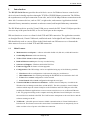
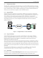
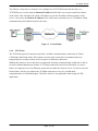
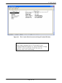
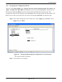
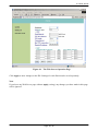
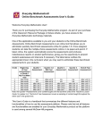
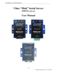
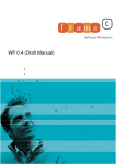
IP Serial Server IP Serial Server IPS-101 (1-port) IPS-102 (2-port) IPS-201 (1-port) IPS-202 (2-port) IPS-204 (4-port) User Manual V2.0 2009.03.09 Page: 1 / 62 IP Serial Server Copyright This document contains proprietary information that is protected by copyright. All rights reserved. No part of this document may be photocopied, reproduced, or translated into another language without express prior written consent of the originator. The software described in this manual is furnished under a license agreement and may be used only in accordance with the terms of that agreement. Disclaimer Information in this document is subject to change without notice and does not represent a commitment on the part of the originator. We provide this document “as is,” without warranty of any kind, either expressed or implied, including, but not limited to, its particular purpose. We reserve the right to make improvements and/or changes to this manual, or to the products and/or the programs described in this manual, at any time. Information provided in this manual is intended to be accurate and reliable. However, we assume no responsibility for its use, or for any infringements on the rights of third parties that may result from its use. This product might include unintentional technical or typographical errors. Changes are periodically made to the information herein to correct such errors, and these changes are incorporated into new editions of the publication. Page: 2 / 62 IP Serial Server Contents 1. Introduction ........................................................................................................................... 8 1.1 Main Features ................................................................................................................... 8 1.2 Communication Modes..................................................................................................... 9 1.2.1 Straight IP Mode ..................................................................................................... 9 1.2.2 Virtual COM Mode ................................................................................................. 9 1.2.3 Paired Mode ............................................................................................................ 9 1.2.4 TCP Probe ............................................................................................................. 10 1.3 Installation and Startup ....................................................................................................11 1.3.1 Package Checklist ..................................................................................................11 1.3.2 Hardware Setup ......................................................................................................11 1.3.3 Software Installation ..............................................................................................11 1.3.4 IP Serial Server Configuration ...............................................................................11 1.3.5 Install Virtual COM Ports ..................................................................................... 13 1.3.6 Check Data Communications................................................................................ 14 2. Hardware Connections ....................................................................................................... 15 2.1 Front/Rear Views ............................................................................................................ 15 2.2 Connectors, Indicators, and Reset Switch ...................................................................... 17 2.2.1 Indicator Lights ..................................................................................................... 17 2.2.2 Power Connector ................................................................................................... 17 2.2.3 Reset Button .......................................................................................................... 17 2.2.4 Ethernet Connector ............................................................................................... 17 2.2.5 Serial Ports ............................................................................................................ 17 3. Installing the IPS Administrator Software ....................................................................... 18 3.1 Software Installation ....................................................................................................... 18 3.1.1 Automatic Installation ........................................................................................... 18 3.1.2 Manual Installation ............................................................................................... 18 3.1.3 Updating an Existing Installation .......................................................................... 20 3.1.4 Opening the IPS Administrator ............................................................................. 21 4. Using the IPS Administrator.............................................................................................. 22 Hardware Setup .............................................................................................................. 22 Software Setup ................................................................................................................ 23 Software Overview ......................................................................................................... 23 4.3.1 Menus .................................................................................................................... 23 4.3.2 Icons ...................................................................................................................... 24 4.3.3 Serial Server List / Virtual COM List ................................................................... 24 4.3.4 Status Bar .............................................................................................................. 25 Search for Servers ........................................................................................................... 25 Setting the Configurations .............................................................................................. 26 4.1 4.2 4.3 4.4 4.5 Page: 3 / 62 IP Serial Server 5. Configuring the IP Serial Server ....................................................................................... 29 5.1 Description of Configuration - System ........................................................................... 29 5.1.1 Model Name.......................................................................................................... 29 5.1.2 Server Name.......................................................................................................... 29 5.1.3 Serial Number ....................................................................................................... 29 5.1.4 Password ............................................................................................................... 30 5.1.5 FW Version............................................................................................................ 30 5.1.6 MAC Address........................................................................................................ 30 5.1.7 DHCP .................................................................................................................... 30 5.1.8 IP Address ............................................................................................................. 30 5.1.9 Netmask ................................................................................................................ 31 5.1.10 Gateway ................................................................................................................ 31 5.1.11 Link Status ............................................................................................................ 31 5.2 Description of Configuration - Port ................................................................................ 31 5.2.1 Baud Rate .............................................................................................................. 32 5.2.2 Data/Stop bits ........................................................................................................ 32 5.2.3 Parity ..................................................................................................................... 32 5.2.4 Flow Control ......................................................................................................... 32 5.2.5 TCP/UDP Protocol ................................................................................................ 32 5.2.6 TCP/UDP Port ....................................................................................................... 33 5.2.7 Delimiter Hex 1 and Delimiter Hex 2 ................................................................... 34 5.2.8 Force Transmit ...................................................................................................... 34 5.2.9 Inter-Byte Gap....................................................................................................... 34 5.2.10 Connection Status ................................................................................................. 34 5.2.11 Serial Type ............................................................................................................ 34 5.2.11.1 Console (Serial Port 1 only) ...................................................................... 34 5.2.11.2 RS-232 ....................................................................................................... 35 5.2.11.3 RS-422 ....................................................................................................... 35 5.2.11.4 RS-485H .................................................................................................... 35 5.2.11.5 RS-485F ..................................................................................................... 35 5.2.11.6 Default Mode ............................................................................................. 35 5.2.11.7 Upgrade Mode ........................................................................................... 35 5.2.12 Serial Timeout ....................................................................................................... 36 5.2.13 TCP Alive Timeout ............................................................................................... 36 5.2.14 TCP Mode ............................................................................................................. 36 5.2.15 Max Connection .................................................................................................... 36 5.2.16 Connection At ....................................................................................................... 36 5.2.17 Remote IP Address ................................................................................................ 37 5.2.18 Apply..................................................................................................................... 37 5.2.18.1 Saving Configuration Data in IPS Administrator ...................................... 37 Page: 4 / 62 IP Serial Server 5.2.18.2 Saving Configuration Data in Console Mode or Telnet ............................ 37 5.2.18.3 Saving Configuration Data in Web Server Interface ................................. 38 6. Installing Virtual COM Ports ............................................................................................ 40 6.1 Installing Virtual COM Port ........................................................................................... 40 6.2 Matching the IPS and Virtual COM Port Settings .......................................................... 42 7. Removing Virtual COM Ports ........................................................................................... 45 7.1 Removing the Virtual COM port using IPS Administrator ............................................ 45 7.2 Removing the Virtual COM Port using Device Manager ............................................... 45 8. Upgrading the IPS Firmware ............................................................................................ 47 8.1.1 Change to Upgrade Mode ..................................................................................... 47 8.1.2 Upgrading the Firmware ....................................................................................... 47 9. Using the Console Mode ..................................................................................................... 49 9.1 Entering Console Mode .................................................................................................. 49 9.2 Console Mode Setup ....................................................................................................... 49 9.2.1 Navigating the Configuration Menus .................................................................... 51 10. Using the Web Server ......................................................................................................... 52 10.1 Setting Server Configurations......................................................................................... 52 11. Using the Telnet ................................................................................................................... 55 11.1 Telnet Login .................................................................................................................... 55 11.2 Navigating the Configuration Menu ............................................................................... 56 12. Technical Data ..................................................................................................................... 57 12.1 Feature List ..................................................................................................................... 57 12.2 Default Settings .............................................................................................................. 58 Appendix A: Well-Known TCP/UDP Port Numbers ................................................................... 59 Appendix B: Serial Port Pin-outs .................................................................................................. 60 Appendix C: Ethernet Cable Pin-outs .......................................................................................... 61 Appendix D: Regulation Information ........................................................................................... 62 Page: 5 / 62 IP Serial Server Figures Figure 1 Figure 2 Figure 3 Figure 4 Figure 5 Figure 6 Figure 7 Figure 8 Figure 9 Figure 10 Figure 11 Figure 12 Figure 13 Figure 14 Figure 15 Figure 16 Figure 17 Figure 18 Figure 19 Figure 20 Figure 21 Figure 22 Figure 23 Figure 24 Figure 25 Figure 26 Figure 27 Figure 28 Figure 29 Figure 30 Figure 31 Figure 32 Figure 33 Figure 34 Figure 35 Figure 36 Figure 37 Figure 38 Straight IP Mode / Virtual COM Mode ............................................................................. 9 Paired Mode..................................................................................................................... 10 Typical Hardware Setup ...................................................................................................11 The IPS Administrator Server List Window .................................................................... 12 The Configurations Window ........................................................................................... 13 Configuring the Virtual COM Port .................................................................................. 14 The Front/Rear Views ...................................................................................................... 15 The Panel Layout of 1-port / 2-port IPS .......................................................................... 15 The Panel Layout of 4-port IPS (IPS-204) ...................................................................... 16 The Install Shield Wizard Window ................................................................................ 18 The Setup Window of IPS Administrator ...................................................................... 19 The Choose Destination Window .................................................................................. 19 The Install Shield Wizard Complete Window ............................................................... 20 The InstallShield Wizard Modify, Repair or Remove Screen ....................................... 20 IPS Administrator displays all IP Serial Servers found ................................................. 21 Ethernet Connection via a LAN .................................................................................... 22 Direct Ethernet Connection using a Crossover Cable ................................................... 22 The IPS Administrator Window .................................................................................... 23 The Search Setup Window ............................................................................................ 26 The Configurations Window ......................................................................................... 27 The Restart Dialogue Box ............................................................................................. 27 The Restarting Dialogue Box ........................................................................................ 28 The Search Server Dialogue Box .................................................................................. 28 The Searching Dialogue Box ......................................................................................... 28 The Server Configurations Window of IPS Administrator ............................................ 29 Pinging using the DOS command window.................................................................... 31 The Server UDP Configuration Screen ......................................................................... 33 The Restart Dialogue Box ............................................................................................. 37 The Console Configuration ........................................................................................... 38 The Web Server Configuration ...................................................................................... 39 The Search Setup Window ............................................................................................ 40 The Found Server Window ............................................................................................ 41 The COMInst Window .................................................................................................. 41 The System Properties Window .................................................................................... 42 The Device Manager Window ....................................................................................... 43 Virtual COM Port Configuration Window .................................................................... 44 The IPS Administrator Window .................................................................................... 45 Confirm Device Removal .............................................................................................. 46 Page: 6 / 62 IP Serial Server Figure 39 Figure 40 Figure 41 Figure 42 Figure 43 Figure 44 Figure 45 Figure 43 Figure 51 Te Port Settings Window ............................................................................................... 48 The Console Mode Screen in the HyperTerminal Window ........................................... 50 Saving and Restarting the Configuration in Console mode .......................................... 51 The Web Server Page..................................................................................................... 52 The Web Server Serial Port Configurations Page.......................................................... 53 The Web Server Operation Page.................................................................................... 54 Saving and Restarting the Configuration....................................................................... 56 2-wire RS-485 Connection ............................................................................................ 60 Ethernet Cable Pin-outs ................................................................................................. 61 Page: 7 / 62 IP Serial Server 1. Introduction The IPS (IP Serial Server) provides the serial device server for Windows hosts to control serial devices located virtually anywhere through a TCP/IP or UDP/IP Ethernet connection. The IPS has the asynchronous serial port connection on one side, and a 10/100 Mbps Ethernet connection on the other side. It connects devices, such as CNC, weight scales, and scanners. Applications include industrial/factory automation, automatic warehouse control, and hospital/laboratory automation. The IPS Windows driver provides Virtual COM port to control the IPS. Virtual COM port provides access to any of the ports on the IPS, as if a real serial port on the computer. IPS can function as a server or client for both TCP and UDP connection. The application scenarios are Straight IP mode, Virtual COM mode, and Paired mode. In Straight IP and Virtual COM modes, IPS should only work as a server. When in the Paired mode one IPS must set as a client and the other must set as a server in both TCP and UDP connection. 1.1 Main Features Multi-interface serial ports -- software selectable for RS-232, RS-422, or RS-485 interface. 10/100 Mbps Ethernet with Auto-detecting TCP or UDP / Client or Server operation Built-in Ethernet switch ports for easy cascaded wiring Software OS Support - Windows 2000/2003/XP/Vista Firmware Upgrade for future revisions/upgrades Configuration of the IPS settings can be accomplished using any of the following methods: 9 Web Server allows configuration via the network using any web browser 9 IPS Administrator for searching and listing the IPS/WIPS servers attached to the LAN 9 Telnet allows remote configuration via the network 9 Serial Console allows local configuration through the serial port Virtual COM Driver Software for Windows - installs virtual COM ports, viewable in the Windows Device Manager under Ports (COM & LPT). The driver installs a virtual COM on windows which maps the virtual COM port to the IP address and TCP/UDP port of the IPS, enabling the Windows applications to access remote serial devices over an IP-based Ethernet LAN. Any program running on the computer and using Windows-based COM ports can access the serial devices attached to the IPS. The LAN becomes transparent to the serial device and the software running on the PC. TCP Probe - selectable protocol ensures reliable communications in Virtual COM mode or Paired mode. This feature restores the connections if communications are temporarily lost at either end due to loss of power or the Ethernet connection. Page: 8 / 62 IP Serial Server 1.2 Communication Modes The IPS enables communication with serial devices over a LAN or WAN. Serial devices no longer are limited to a physical connection to the PC COM port. They can be installed anywhere reachable by the LAN/WAN using TCP/IP or UDP/IP communications. This allows traditional Windows PC software access to serial devices anywhere on the LAN/WAN network. 1.2.1 Straight IP Mode Straight IP mode allows applications using TCP/IP or UDP/IP socket programs to communicate with the asynchronous serial ports on the IPS. In this type of application the IPS is configured as a TCP or UDP server. The socket program running on the PC establishes a communication connection with the IPS. The data is sent directly to and from the serial port on the server. When using UDP protocol the server can be configured to broadcast data to and receive data from multiple IP addresses. Figure 1 1.2.2 Straight IP Mode / Virtual COM Mode Virtual COM Mode Virtual COM mode allows the user to provide a virtual COM port on the computer. Windows programs using standard Windows API calls are able to interface to virtual COM ports. When a program on the PC opens the new COM port, it communicates with the remote serial device connected to one of the ports on the IPS. After connection, the LAN is transparent to the program and serial device. Applications are able to work just as if the serial device is connected directly to a physical COM port on the computer. The virtual COM software converts the application’s data into IP packets, sends it across the network to the IPS, which converts the IP packet back to serial data and sends the data out a serial port located on the IPS. To use this mode, the IPS must be set to either TCP/server or UDP/server with a designated communication port number. The virtual COM driver is the TCP or UDP client. 1.2.3 Paired Mode Paired Mode is also called Serial Tunneling mode. In this mode any two serial devices that can communicate with a serial link will be able to communicate using two IPS and the LAN. Page: 9 / 62 IP Serial Server Two IPS are connected to a network, one configured as a TCP/UDP client and the other as a TCP/UDP server. In the setup the Remote IP address field of the server must contain the address of the client. This will allow the client’s IP address to pass the IP address-filtering feature of the server. Conversely, the Remote IP address of the client must contain the server’s IP address. Both communication port numbers must be the same. Figure 2 1.2.4 Paired Mode TCP Probe The TCP Probe protocol connection provides a reliable communications connection in Virtual COM mode and Paired mode. This feature can restore the connection if communications are temporarily lost at either end due to loss of power or Ethernet connection. Without this feature a device that loses a connection and stops communicating would not be able to reconnect without human intervention. A TCP data connection can be lost when there is a power failure or temporary loss of an Ethernet connection on either the client or server. If a loss occurs the Probe feature will try to reconnect the TCP data connection every five seconds until communications is established again. The Probe feature is not applicable when using an UDP application. Page: 10 / 62 IP Serial Server 1.3 Installation and Startup For descriptive purposes this section considers a typical configuration consisting of a computer connected via an Ethernet LAN to the IPS connected to the RS-232 port of a serial device. 1.3.1 Package Checklist The IP Serial Server is shipped with the following items included: 9 The IP Serial Server unit 9 Power Adapter 9 Quick Start Guide 9 CD-ROM Disk (Documentation and software) 9 Footpads set 1.3.2 Hardware Setup Figure 3 Typical Hardware Setup Step 1: Connect the IPS to the network using a standard Ethernet cable. Step 2: Connect the IPS to the RS-232 port on the serial device. Note: If the serial device is configured as a DCE use a straight-through serial cable. If the serial device is configured as a DTE use a crossover (null modem) cable. Step 3: Apply power to the IPS. 1.3.3 Software Installation Using the CD included with the IP Serial Server, install the IPS Administrator software on the host computer. 1.3.4 IP Serial Server Configuration Step 1: Open the IPS Administrator software. It will automatically search for any reachable IPS devices. A list of all IPS connected to the LAN will appear in the IPS List window. Page: 11 / 62 IP Serial Server Figure 4 The IPS Administrator Server List Window Step 2: Double click the desired IPS port on the list to bring up the Server Configurations screen. Page: 12 / 62 IP Serial Server Figure 5 The Configurations Window Step 3: Change the Server Configurations as required. (a) Disable DHCP, set appropriate static IP, Netmask and Gateway addresses from your Network Administrator (recommended), or enable DHCP to allow the IPS to obtain an IP address from DHCP server. (b) Set the Serial type to RS-232 to match the serial device connected to the IPS. Note: the default is at Console mode, so you have to change to RS-232 mode for data transmission. (c) Set Baud Rate, Data/Parity/Stop, and Flow Control to match the configuration of the serial device connected to the IPS serial port. Step 4: When the parameters have been set, click Apply. Following the prompts in the dialogue boxes, Restart the IPS and Search all reachable servers again. Step 5: Re-enter Server Configurations to verify the changes have taken effect, or to view/change the configuration of other ports. Each port must be configured separately. 1.3.5 Install Virtual COM Ports Step 1: From the Windows Start menu, run the Install Virtual COM utility included with the IPS Administrator software. Page: 13 / 62 IP Serial Server Step 2: Search for all servers on the network Step 3: Select a port and map it to an unused COM port (e.g. Port 3). Configure it for TCP protocol and the appropriate IP address (determined in the last section). Figure 6 1.3.6 Configuring the Virtual COM Port Check Data Communications Step 1: Run the terminal emulation program (such as HyperTerminal or PuTTY). Select the COM port (e.g. Port 3). Step 2: Set Baud Rate, Data/Parity/Stop, and Flow Control to match the configuration of the serial device connected to the IPS serial port. Step 3: Communications with the serial device should now be operational. Page: 14 / 62 IP Serial Server 2. Hardware Connections 2.1 Front/Rear Views Figure 7 Figure 8 The Front/Rear Views The Panel Layout of 1-port / 2-port IPS Page: 15 / 62 IP Serial Server DIN-Rail screw hole Wallmount screw hole Figure 9 The Panel Layout of 4-port IPS (IPS-204) Page: 16 / 62 IP Serial Server 2.2 Connectors, Indicators, and Reset Switch 2.2.1 Indicator Lights LED Power Indication Red – power indication ON: power is applied Ready Green -- blinking per second when system is ready LEDs on RJ45 connectors Ethernet Link/Act/10/100Mbps: Orange -- 10BaseT Ethernet connection established Green -- 100BaseT Ethernet connection established Blinking: when data in activity ON: when no data in activity and link connected When set up as a TCP server: Steady Green - client has made a connection, communications starting LEDs of Serial port (4-port model) Flashing Green – data present at the serial port Light off – connection closed When setup in UDP mode: Steady Green – port ready Flashing Green – data is being transmitted or received 2.2.2 Power Connector Plug the plug from the included power supply into the power jack and then plug the supply in. When power is applied the Red power light will illuminate. The tip of the power plug is positive; the sleeve is negative. 2.2.3 Reset Button This switch resets the unit, similar to the effect of removing/applying power. The Reset switch is recessed to avoid accidental operation. To reset the unit, insert a small plastic tool, press lightly and hold for three seconds. The Link and Ready lights will go out and then come back on. 2.2.4 Ethernet Connector The IPS has built-in Ethernet switch and provides dual standard RJ-45 receptacle mounted in the top edge of the chassis. The IPS can be connected to an Ethernet hub, switch, or wall plate using a standard straight-through RJ-45 (male) Ethernet cable. To connect directly to an RJ45 Ethernet port on a PC or laptop a crossover Ethernet cable must be used. 2.2.5 Serial Ports The IPS has one/two/four serial ports. The port can be configured as RS-232, RS-422, or RS-485 interface. Page: 17 / 62 IP Serial S Serverr 3. Insstalling th he IPS Ad dministrator Softw ware The Windoows-based IPS I Adminiistrator andd Virtual COM C Port software s maakes configu uration fast and eaasy. If using Windows, installing thhe IPS Adm ministrator software annd setting up u virtual COM portss to configuure the IPS is i recommended. 3.1 Sofftware Insttallation The IPS Administrat A tor software includes: 9 IPS Administra A tor 9 Installl / Removee Virtual COM C Ports 3.1.1 Au utomatic Installation Step 1:Inserting the CD C in the CD D-ROM shoould automaatically launnch the Insttall Shield Wizard. W 3.1.2 Maanual Instaallation Step 1:To manually sttart the softtware installlation, from m the Windows Desktopp, click Starrt button andd click Run item. At thhe Run comm mand line ty ype E:\Instaall_IPS\setuup.exe and click c OK (E: is the drivee letter for thhe CD ROM M.), or open n the File manager m and double clicck E:\IInstall_IPS\\setup.exe. Thee Install Sh hield Wizarrd window will w be disp played. Figu ure 10 Th he Install Sh hield Wizard Window w w appeears, click Next. N Step 2:Whhen the IPS Administraator Setup window P Page: 18 / 62 2 IP Serial Server Figure 11 The Setup Window of IPS Administrator Step 3:When Choose Destination Location appears, click Next. The installation progress will be shown until complete. Figure 12 The Choose Destination Window Step 4:Click Finish when the Install Shield Wizard Complete dialogue appears. When finished, dialogue box will close. Page: 19 / 62 IP Serial Server Figure 13 The Install Shield Wizard Complete Window 3.1.3 Updating an Existing Installation If an older version of the IPS Administrator software is already installed, the Modify, repair or remove the program window will appear when the installation process is initiated: Figure 14 The InstallShield Wizard Modify, Repair or Remove Screen The recommended procedure is to Remove all installed components first. Once the software has been removed, Install the new software. Page: 20 / 62 IP Serial Server 3.1.4 Opening the IPS Administrator Step 5:If the WIPS is not already connected to the network or to the Ethernet port on the computer, connect it. Apply power. The PWR indicator should light red, the Link LEDs on the Ethernet connector should indicate which type of Ethernet connection has been made and the RDY LED will flash indicating configuration can begin. Step 6:Start the IPS Administrator software. In Windows Desktop, click: Start > All Programs > IPS > IPS Administrator As soon as the IPS Administrator opens it will initiate Searching Server and after a few seconds the IP Serial Server List will display all IP Serial Server devices (wire or wireless models) on the network. Figure 15 IPS Administrator displays all IP Serial Servers found Page: 21 / 62 IP Serial Server 4. Using the IPS Administrator The IPS Administrator software allows: ¾ Searching for servers connected to the network 4.1 ¾ Displaying and changing the configuration of those servers ¾ Installing virtual COM ports on a computer ¾ Displaying and configuring virtual COM ports ¾ Uninstalling virtual COM ports on a computer ¾ Upgrading the IPS firmware ¾ Monitoring Port Status ¾ Saving and Loading Configuration Files Hardware Setup Step 1: Connect the IPS to the LAN or to a computer Ethernet port. Figure 16 Ethernet Connection via a LAN Figure 17 Direct Ethernet Connection using a Crossover Cable Step 2: Apply power. The red Power indicator will light, the Link indicator lights when an Ethernet connection is made, and the Ready indicator will flash. Page: 22 / 62 IP Serial Server 4.2 Software Setup Step 3. To run the IPS Administrator, from the Windows Desktop click: Start > All Programs > IPS > IPS Administrator As soon as the IPS Administrator opens it will initiate Searching Server and after a few seconds the IPS List will display all IPS devices on the network. Figure 18 The IPS Administrator Window 4.3 Software Overview The IPS Administrator window provides the following information: 4.3.1 • Menus (Server, View, Exit, Help) • Icons (Search Server, Virtual COM Mapping, Uninstall Virtual COM, Port Status, Upgrade Firmware) Menus Server • Search Server - Searches for IPSs on the network and brings back configuration information that will be displayed in the Server Configurations window. • Virtual COM Mapping - Selects the Virtual COM List. Double clicking on any COM port in the Virtual COM List brings up a window that allows changing the virtual COM settings such as Flow Control, Protocol, IP address, and Port Number. Virtual COM settings must match IPS port settings. • Uninstall Virtual COM - Allows virtual COM ports to be uninstalled from the IPS Administrator window. • Port Status - Brings up a screen that displays the following information associated with the selected serial port: Serial TX: Displays the number of bytes of data sent to the serial device since the IP connection was established. Page: 23 / 62 IP Serial Server Serial RX: Displays the number of bytes of data received from the connected serial device since the IP connection was established. DTR/RTS: The DTR/RTS Port Status indicator displays the current logic state of the DTR and RTS hardware handshake (output) lines for the selected IPS port (1 = asserted, 0 = not asserted). DCD/DSR/CTS: The DCD/DSR/CTS Port Status indicator displays the current logic state being received on the DCD, DSR and CTS hardware handshake (input) lines for the selected IPS port (1 = asserted, 0 = not asserted) Status: Indicates whether the client software has made a connection with the IPS. IP Address: Displays the IP address of the connected client when there is a client connection • Upgrade Firmware - Used when downloading new firmware to the IPS. • Save Configuration File - Allows the user to save the current configuration information to a file with a .vcom extension. • Load Configuration File - Allows the user to load a configuration file. View Provides three viewing options for the IPS Administrator screen: • Status Bar – allows the Status Bar at the bottom of the screen to be viewable or hidden. • Split – allows the position of the split between the Icons pane and the Virtual COM List / IP Serial Server List panes to be dragged horizontally using the mouse. • Allows you to Exit the IPS Administrator program • Accesses the About vcomui (virtual com user interface) dialogue box, which indicates the software version number Exit Help 4.3.2 Icons The functions Search Server, Virtual COM Mapping, Uninstall Virtual COM, Port Status, Upgrade Firmware can also be selected using icons located in the top window. 4.3.3 Serial Server List / Virtual COM List To make management of lists of IPS easier, lists can be sorted by clicking on any tab heading. Scrolling bars facilitate scrolling through long lists. Page: 24 / 62 IP Serial Server Serial Server List • Server Name - Displays the name of the IPS. The name is listed once for each port. • IP Address - Displays the IP Address for the IPS. All ports in an IPS have the same the same IP address. • Port - Displays the port number for each IPS port. • Protocol - Displays the currently selected TCP or UDP mode for the IPS. • Status - The Status indicates the mapped virtual COM port condition. Not Connected is shown when a program does not have the port Open. Connected is shown when that mapped port is Open for use. • COM - Displays the name of the computer COM port mapped to each IPS port. If no computer port has been mapped it displays Not mapped. • Interface – Displays the interface type of the serial port. Virtual COM List 4.3.4 • COM Name - Displays the number of the COM port mapped to each IPS port. • IP Address - Displays the IP Address for the IPS. All ports in an IPS have the same IP address. • Protocol - Displays the currently selected TCP or UDP mode for the IPS. • Port - Displays the port number for each IPS port. • Flow Control - Indicates what type of flow control is configured for each port. • Status - Indicates whether each port is currently In Use or Not Used. Status Bar Displays the current status of the software in the bottom, left corner of the screen 4.4 • Ready • Waiting for the server to restart… • Searching reachable servers… Search for Servers Upon opening the IPS Administrator software it will automatically execute Search Server to search for all reachable IPSs. Step 4: To manually initiate a search for servers, click the Search Servers icon. The Search Setup box will appear. It provides two options for searching for servers on the network: • Specify the IP Address of the IPS or • Search all reachable servers Page: 25 / 62 IP Serial S Serverr Figure 19 The Searrch Setup Window W Steep 5: Enterr the IP Add dress assignned to the desired IPS or o click Seaarch all rea achable serveers, then OK K. IP Address is used to t find IPS units that arre not on th he same subneet. (Routers on the netw work will bllock the stanndard broaddcast used to o find serverrs if Search h all reachaable serverss is selectedd.) The userr must set an n IP addreess that confforms to thee LAN addrressing scheeme. The Searching S w window is shhown until all a active IP PSs on the L LAN are listted in the IPS List L window w. 4.5 Settting the Coonfiguratioons The Configurations window w dispplays the cuurrent config gurations foor the currenntly selected d server. Steep 6: To oppen the Con nfigurationss window, highlight h the IPS in thee IPS List window, w doublle-click to open. o The Configurati C ions window w is used to o configure and store thhe configuraation settinngs. Details for setting Configurati C pter. ons are desccribed in thhe next chap P Page: 26 / 62 2 IP Serial Server Figure 20 The Configurations Window Note: IPS Administrator Navigation: • • • • Use the mouse to select the property and parameters or Tab to move to the next property Tab+Shift to move back to previous property Arrows to move between configurations or change values or contents of the current configuration • Enter to select Apply or Cancel Step 7: After configuring as needed, click Apply to store the configuration in the server. The following window will appear: Figure 21 The Restart Dialogue Box Page: 27 / 62 IP Serial S Serverr Step 8:Click Yes to reestart. The following f diialogue box x will appeaar: F Figure 22 The Restarting Dialoogue Box After eightt seconds a dialogue boox will ask whether w you u want to seearch for alll reachable servers s again. Figgure 23 T Search Server Diaalogue Box The While the IPS I is searcching for alll reachable servers s the following dialogue d boxx appears: F Figure 24 The Searcching Dialoogue Box After that port p has beeen applied you y may waant to re-entter Server Configurati C ions to veriffy the changes haave taken efffect, or to view/change v e the config guration of other o ports. Each port must m be configuredd separately.. P Page: 28 / 62 2 IP Serial Server 5. Configuring the IP Serial Server The IPS can be configured using any of four different user interfaces: the IPS Administrator software, Console Mode, Telnet or the Web Server. The Configurations described in this chapter can be changed from any of these user interfaces. 5.1 Description of Configuration - System Figure 25 The Server Configurations Window of IPS Administrator 5.1.1 Model Name The model highlighted to open for configuration. 5.1.2 Server Name This field displays the name that has been assigned to the IPS. A new Server Name of up to 16 characters can be entered. If more than one IPS is connected on the LAN it is recommended that a new name be assigned to each. When the IPS Administrator finds an IPS on the LAN it displays the server name and IP Address allowing the user to distinguish between IPS. 5.1.3 Serial Number Each IPS has a unique serial number. This is fixed and cannot be changed. Page: 29 / 62 IP Serial Server 5.1.4 Password Entering a password activates a security feature on the IPS. Once a password is entered it will be required to access the menu and make changes. 5.1.5 FW Version It shows the currently loaded firmware version. 5.1.6 MAC Address The MAC address is fixed and cannot be changed. It is assigned in the factory. Every Ethernet device manufactured has it own unique MAC address. 5.1.7 DHCP DHCP servers are a part of numerous LAN management systems. The DHCP field provides two choices: Disable and Enable. Disable is the normal, or default, setting. When enabled, the IPS will send a DHCP request to the DHCP server, which will assign a dynamic IP address, net mask, and gateway to the IPS. If a DHCP server is not available on the network the IPS will time out after 10 seconds and the default values will remain. When DHCP is enabled, the IP Address, Netmask and Gateway fields become inaccessible and cannot be changed by the user. Note: A dynamic address assigned by the DHCP server may change if the server loses the Ethernet connection or power is removed. The host (client) communication software requests a connection to the specific IP address of the IPS. If the DHCP reassigns a different IP address the software will not be able to communicate with the hardware. Therefore, obtaining a fixed IP from DHCP server or using a static IP address is recommended. 5.1.8 IP Address Software or hardware attempting to access the IPS via the network must know the IP Address of the server. A static IP address is retained and remains the same each time the server is powered up or starts/restarts. The default IP address of the IPS is printed on a label on its bottom cover. Entering an appropriate address in the IP Address field and updating the server will change the server’s IP address. The network administrator can assign/establish the static address or group of addresses to be used. The IP Address of the IPS can be confirmed using the DOS Ping command. Notes: To use Ping to check for communications: - Access a DOS window (in Win-XP click Start, then Run) Page: 30 / 62 IP Serial Server - At run prompt enter: CMD - In the DOS window enter: Ping xxx.xxx.xxx.xxx (IP address for the server to be confirmed) - The command will return the Ping results indicating 4 replies Figure 26 5.1.9 Pinging using the DOS command window Netmask The default LAN netmask is configured for a Class C address. The user may change this. Default is 255.255.255.0 5.1.10 Gateway The Gateway IP address allows users to access the IPS from outside the LAN. 5.1.11 Link Status Link status automatically displays the type of Ethernet connection. It will either display 10BaseT or 100BaseTX in full duplex or half duplex. This will depend on the LAN, switches, hubs used in the LAN topology. 5.2 Description of Configuration - Port Each serial port has one configuration page for easy configuration settings. Click to port number interested to open the configuration page. Note: any changes to Configurations must be Applied (Saved) or the IPS will not retain them. Page: 31 / 62 IP Serial Server 5.2.1 Baud Rate The serial port baud rate on the IPS must match the serial baud rate of the connected device unless using Virtual COM Mode. In Virtual COM Mode the software program will establish serial settings. 5.2.2 Data/Stop bits Set this to match the data format used by the serial device connected. 5.2.3 Parity Set this to match the data format used by the serial device connected. 5.2.4 Flow Control The Flow Control setting must match the requirements of the serial device connected. Note: Select None when setting the port as RS-485 or 4-wire RS-422. 5.2.5 TCP/UDP Protocol Select TCP (Transmission Control Protocol) or UDP (User Datagram Protocol) protocol. TCP Mode If the application does not require a UDP connection, select TCP. TCP guarantees reliable Page: 32 / 62 IP Serial Server communication with error checking whereas UDP provides faster transmission. UDP Mode When UDP mode is chosen the Serial timeout, TCP alive timeout, TCP mode, Max connection, Connection at and Remote IP address fields are replaced with the following fields: Destination UDP/IP addresses, UDP Port, and Source UDP/IP addresses. In this mode the server can be configured to broadcast data to and receive data from multiple IP addresses. Four IP address range fields are provided. Figure 27 The Server UDP Configuration Screen Notes: 1. Destination UDP/IP addresses: In order not to over-flood the UDP traffic, we should keep the Destination UDP/IP addresses (broadcast range) as small as possible. 2. Source UDP/IP addresses: to filter the incoming IP/Port, i.e., only accept UDP packets that come from the assigned source addresses. 5.2.6 TCP/UDP Port This sets the port number for connection. The default port number for the IPS is 7000 for serial port 1. In all modes of operation, Straight IP or Virtual COM, the port number set in the Server Configurations menu must match the Virtual COM or socket software port settings. Note: Page: 33 / 62 IP Serial Server Example: The Virtual COM default setting is TCP/UDP Port 7000. If the port # property is changed to 7001, the virtual COM port will have to be changed to 7001. The hardware settings can be changed from the IPS Administrator or Console Configuration Menu. The Virtual COM port setting also can be changed within the Device Manager of the computer on which it is installed. 5.2.7 Delimiter Hex 1 and Delimiter Hex 2 These fields allow the user to enter two ASCII characters (in hex format) that delimit the beginning and end of a message. When a message with both these delimiters is received at the serial port, the data contained in the serial buffer is placed in an Ethernet packet and sent out the Ethernet port. If only Delimiter 1 is set (Delimiter 2 is zero or blank), upon receiving Delimiter 1 the IPS will put all the data in the serial buffer in an Ethernet packet and send it out the Ethernet port. If serial data greater than 1 kilobyte is received it will automatically be placed in an Ethernet packet and sent out the Ethernet port. 5.2.8 Force Transmit This field allows the user to set a maximum time limit between transmissions of data. The value set in this field multiplied by 100 ms determines the Force Transmit time. When the elapsed time reaches the time configured in this field, the TCP/IP protocol will pack the data currently in the serial buffer into a packet and send it out the Ethernet port. 5.2.9 Inter-Byte Gap The Inter-byte timer defines the time elapse since last data byte received, e.g., set to 10sec, if expire, means that it has passed 10sec and no data received since last byte received). When inter-byte timer expired, the TCP/IP protocol will pack the data currently in the serial buffer into a packet and send it out the Ethernet port. 5.2.10 Connection Status This field indicates whether a serial port is connected via the IPS to a virtual COM port of a device on the network. 5.2.11 Serial Type Each Serial Port allows configuration to one of the following operation modes: 5.2.11.1 Console (Serial Port 1 only) The Serial Port 1 is default set to Console mode. In Console Mode the Configuration Menu can be accessed from a PC by connecting its RS-232 serial port to the IPS Serial Port 1 (at Console mode). Since the computer is a DTE device, and the serial ports are configured as DTE (with DB-9M connectors), a null modem crossover cable must be used. Page: 34 / 62 IP Serial Server In Console Mode the default serial port settings are: 115200 baud, 8 data bits, 1 stop bit, and No parity, From Windows, HyperTerminal with VT100 terminal emulation can be used for Console Mode configuration. 5.2.11.2 RS-232 Every Serial Port, except port 1, is default set to RS-232 mode. In RS-232 Mode the currently selected serial port is configured as an RS-232 interface supporting eight RS-232 signal lines plus Signal Ground and is configured as a DTE, like a computer. Signals are single ended and referenced to Ground. To use handshaking, Flow Control must be set to RTS/CTS during Configuration. 5.2.11.3 RS-422 In RS-422 Mode the currently selected serial port is configured as an RS-422 interface supporting four RS-422 signal channels with full duplex operation for Receive, Transmit, RTS (Request To Send) and CTS (Clear To Send). The data lines are differential pairs (A & B) in which the B line is positive relative to the A line in the idle (mark) state. Ground provides a common mode reference. To use handshaking, Flow Control must be set to RTS/CTS during configuration. 5.2.11.4 RS-485H In RS-485H Mode the currently selected port is configured as an RS-485H interface supporting transmit (TX) and receive (RX) signal channels using 2-wire, half-duplex operation. The data lines are differential with the Data B line positive relative to Data A in the idle (mark) state. Ground provides a common mode reference. 5.2.11.5 RS-485F In RS-485F Mode the currently selected port is configured as a four-wire RS-485 interface supporting transmit lines TXDB(+) and TXDA(-) and receive lines RXDB(+) and RXDA(-) for full duplex operation. The lines are differential with the B line positive relative to A in the idle (mark) state. Ground provides a common mode reference. 5.2.11.6 Default Mode When Default Mode is selected and the Server Configurations are Applied (Saved), all the configuration settings (except the password) return to their default values. 5.2.11.7 Upgrade Mode In Upgrade Mode firmware can be uploaded from a PC via its serial port to the IPS serial port 1. Upgrading also can be accomplished via the network connection, using the IPS Administrator software and a virtual COM port. In Upgrade Mode the default serial port settings are: 9600 baud, 8 data bits, No parity, and 1 stop bit. However, usually the baud rate typically is reconfigured to 115200 kbps to facilitate a faster Page: 35 / 62 IP Serial Server upload speed. 5.2.12 Serial Timeout Default for the Timeout property is 0, or no timeout. Setting Timeout to any value between 1 and 65535 seconds activates it. If Timeout is set to 5 seconds and the IPS is configured as a Server, the Client makes a connection and communications starts. If communications are idle for 5 seconds the IPS will close the TCP session and make itself available for another client connection request. 5.2.13 TCP Alive Timeout This is "TCP keep-alive" function replacing "TCP alive timeout" function. This feature is effective in server mode only. This field can be set to any value between 0 and 255 minutes. Value 0 disables the function. If enable, the unit will query the client regularly, if the client fail to respond in the period set in the "TCP alive timeout" the IPS will close the TCP session. So it can prevent TCP connection lockup. This function is especially useful for WINSOCK application, so the IPS won't be deadlocked when user's application closed improperly or the network link interrupt. Note: The TCP Probe function is for VCOM application, not for WINSOCK application. 5.2.14 TCP Mode The Connection Mode field has three options: Server, Client and Client (no Probe). When Client or Client (no Probe) is selected the Connection at field automatically becomes active (allowing the user to select Power up or Data Arrival). • When using the Virtual COM Port feature, select Server. • When using a TCP or UDP Socket program, select Server. • When using Paired Mode communication between two IPSs, set up one as a Client and the other as a Server. • When connecting to a server that does not support Probe, select Client (no Probe). 5.2.15 Max Connection This field allows the user to configure the IPS to have up to eight TCP connections. 5.2.16 Connection At When the Connection Mode field is set to Client or Client (no Probe), this field becomes active, allowing the IPS (acting as a client) to connect to the server either on Power up or on Data Arrival (first character arriving). Page: 36 / 62 IP Serial S Serverr 5.2.17 Rem mote IP Ad ddress This is a seecurity featuure activated by enterinng the IP ad ddress of thee desired cliient. The IPS will only comm municate witth the listedd IP address and reject all a others. The defaullt setting is 255.255.25 2 5.255., which will disaable the filteer function aand will passs all TCP packets. pply 5.2.18 Ap Server Connfigurationss must be appplied (saveed) separately for each serial port. 5.2.18.1 Saving S Con nfiguration n Data in IP PS Adminisstrator From the Configurati C ions screen, click the Apply A butto on to store thhe configuraation setting gs for the currently selected portt. The vcom mui dialoguee box will appear a indicating you m must restart the device before the new settinggs will take effect. Clickk Yes. Figure 28 The Resttart Dialogue Box After that port p has beeen applied you y may waant to re-entter Configurations to vverify the ch hanges have takenn effect, or too view/channge the configuration of o other portts. Each porrt must be configured c separately. S Con nfiguration n Data in Console Mod de or Telneet 5.2.18.2 Saving Saving Serrver Configuurations is done d from the t Propertties screen. Access A the Properties screen by tabbing thrrough the Page list of screens s on the t left side of the winddow and higghlighting Apply. A There are four f optionss shown on the right sidde of the Prroperties sccreen: Applly, Default, Reload and Restarrt. Use Tab b, Backspacce, or arrow w keys to mo ove the curssor to the opption position, and then press Enter. P Page: 37 / 62 2 IP Serial Server Figure 29 The Console Configuration • Apply -- stores the configuration data to the IPS flash memory and resets it. • Default -- restores the configuration data to factory default settings. • Reload -- restores the configuration data to the last values stored in the flash memory. • Resart -- re-boots the IPS, making it available for a client connection. 5.2.18.3 Saving Configuration Data in Web Server Interface The Web Server interface provides the same updating options as Console Mode and Telnet. These are located at the bottom of Web Server page. If a field is changed, you must click Apply before leaving that page or the changes will be ignored. Page: 38 / 62 IP Serial Server Figure 30 The Web Server Configuration Page: 39 / 62 IP Serial S Serverr 6. Insstalling Virtual V CO OM Portss The Virtuaal COM Poort feature allows a Winddows platforrm softwaree, using stanndard API calls, c to be used in an Ethernet appplication. The Installl Virtual COM Port software addds an IPS (C COM#) portt to the com mputer. This shows up in the Deviice Manageer. The COM M number can c be seleccted from a list of availlable numbeers. For example, inn a computeer already having h a CO OM1 and CO OM2, COM M3 to COM 2254 are available for the IPS. It is i recommeended that COM C Port 5 or higher be b selected. The virtuall COM port looks like a standard COM port to t most Winndows based applicatio ons which allows the sooftware to open o a connectionn with the seerial port loccated anywhhere on the LAN/WAN N. When usiing the virtu ual COM port the IPS S is configuured as a TC CP or UDP Server. S 6.1 Insstalling Virtual COM Port Steep 1: From the t Window ws Desktop p, click: Start > All Programs > IPS > Install Virtual V COM M The Seearch Setup p window will w appear. Steep 2: Select the Search h all reachaable serverss check boxx, and then cclick OK. Figure 31 The Searrch Setup Window W The prograam searchess the LAN for f all availaable IPS. When W compleete, the Fou und Server window appears annd displays a list of the servers thatt were found d. P Page: 40 / 62 2 IP Serial Server Figure 32 The Found Server Window Step 3: Select the IPS at the IP Address to be mapped to a virtual COM port, and then click Install. Figure 33 The COMInst Window The Protocol TCP/UDP, IP Address, and Port Number will mirror the settings of the selected IPS. The default Flow Control setting is None. RTS/CTS can be selected if used by the application program and serial hardware. The IPS must be set to match. Page: 41 / 62 IP Serial Server 6.2 Matching the IPS and Virtual COM Port Settings The settings of the virtual COM ports in the Device Manager and the IPS Configuration Menu must match. If the settings do not match, the virtual COM ports will not work. If these settings are changed in the Device Manager, it will only affect the operation of the virtual COM port. It will not change the settings stored in the IPS. Use the IPS Administrator to change the IPS settings. Step 1: Use Device Manager to view new ports. Confirm the virtual COM ports in the Device Manager. Figure 34 The System Properties Window Step 2: Double-click Ports to view the list of COM port numbers. The installed Virtual COM port will be displayed as IPS (COM #). Page: 42 / 62 IP Serial Server Figure 35 The Device Manager Window Step 3: In the Device Manager select the IPS (COM #). Double-click it to bring up the Properties window. Page: 43 / 62 IP Serial Server . Figure 36 Virtual COM Port Configuration Window Step 4: Click the Configuration or Port Settings tab. This screen allows the settings to be changed if necessary. Click Cancel to keep the existing settings. Step 5: Click OK to change the settings. Use Refresh in the Device Manager if Windows does not auto refresh. Page: 44 / 62 IP Serial Server 7. Removing Virtual COM Ports The IPS Administrator software Uninstall Virtual COM Port feature will remove a mapped COM port in the Device Manager of Windows 2000/2300/ XP/Vista operating systems. 7.1 Removing the Virtual COM port using IPS Administrator Step 1: From the Windows Desktop, click: Start > All Programs > IPS > IPS Administrator Step 2: In the IPS Administrator window, click the Virtual COM Mapping icon. Highlight the mapped COM port number to be removed. Figure 37 The IPS Administrator Window Step 3: Click the Uninstall Virtual COM icon. The Administrator will ask for conformation. Click OK to complete the uninstall procedure. 7.2 Removing the Virtual COM Port using Device Manager Step 1: From the Windows Desktop click: Start > Settings > Control Panel Step 2: Click the System icon. Step 3: Click Device Manager in the Systems Properties window. In the Device Manager dialogue click the + next to Ports (COM & LPT) to expand. Step 4: Highlight IPS (COM #) to be removed and click the Action tab at the top of window, then click Uninstall. A confirm Device Removal window will appear. Page: 45 / 62 IP Serial Server Figure 38 Confirm Device Removal Step 5: click OK to proceed. The IPS (COM #) will be removed and the Device Manager window will refresh and display the remaining COM ports Page: 46 / 62 IP Serial Server 8. Upgrading the IPS Firmware New IPS firmware updates may become available through the website for installation into the server. The firmware can be uploaded using either a virtual COM port connection or hardware COM port connection. The IPS Administrator software can upload new firmware to the server using a direct PC connection via the IPS serial port or using a virtual COM port. Notes: 1. Have a folder to hold the firmware file that will be uploaded to the IPS. 2. If connecting directly to a computer serial port, use a null modem cable between the Computer RS-232 port and the IPS serial port 1. 8.1.1 Change to Upgrade Mode Step 1: In the IPS Administrator, IP Serial Server List window, double click the server to be upgraded. The Configurations window will appear. Step 2: If using a direct connection to upload the firmware to the IPS, set the baud rate to 115200 for the fastest possible upload. Step 3: Set the Serial type field to Upgrade and click the Apply button. Step 4: Click Yes on the vcomui dialogue to restart the IPS. 8.1.2 Upgrading the Firmware Step 5: Double-click the Upgrade Firmware icon. Step 6: In the Upgrade window, click Browse. The Open dialogue box will appear. Locate the folder on your PC that contains the firmware .hex file. Select the file and click Open. The Open dialogue box will disappear. Step 7: In the Upgrade window select the serial port to be used in transferring the firmware. 1. If connected directly from the PC to an IPS port 1 it will typically be COM1 or COM2 2. If using a virtual COM port to upgrade via the network, identify the virtual COM number and address mapped to Port 1 on the IPS. Step 8: Click Upgrade Step 9: In the Port Settings window set the Bits per second, Data bits, Parity and Stop bits to the same values as set up in the Configurations window. Click OK. Page: 47 / 62 IP Serial S Serverr Figure 399 Te Port Settings Window W Steep 10: Upggrade progrress will be shown untiil the messaage Upgrad de finished! is shown. Clickk OK. P Page: 48 / 62 2 IP Serial Server 9. Using the Console Mode Before the IPS is installed on a LAN the Console mode can be used to change the settings from the defaults. The IPS is shipped with Serial type in Console mode. Connect a crossover (null modem) cable between the COM port on the computer and the serial port 1 on the IPS. 9.1 Entering Console Mode Enter Console mode via IPS Administrator: 1. Enter the IPS Administrator, open the Server Configurations, and set the serial port 1 to 9600 baud and 8-N-1. Set the Serial type to Console. 2. Click Apply to take effect the settings. Enter Console mode via Web Page: 1. Use Internet Browser to log in Web server. 2. 3. 9.2 Enter the Serial port page, set the Serial type to Console. Click Apply, and then Reboot Console Mode Setup Step 1: Apply power to the IPS. The power and ready LED will light. Step 2: Using a VT100 Terminal emulation program (such HyperTerminal or PuTTY) open the computer COM port connected to the IPS (via an RS-232 crossover / null modem cable). Step 3: Configure a terminal emulation program with the following settings: Baudrate = 9600 Data/stop bits = 8-1 Parity = none Flow control = none Click OK Step 4: Enter the Console mode via IPS Administrator or Web page. Step 5: To view the Configuration Menu, press the space bar. The menu will appear in a second. Page: 49 / 62 IP Serial Server Figure 40 The Console Mode Screen in the HyperTerminal Window Note !!! Please set the Emulation type to VT100 mode in your Terminal Emulation Program (e.g., HyperTerminal) or simply use PuTTY (select serial mode), so the left-arrow & right-arrow keys can be functioning. Page: 50 / 62 IP Serial Server 9.2.1 Navigating the Configuration Menus There are six Console Mode pages: System, Network, Serial, Operation mode, Port status, and Apply, and Help. Tab, Back Space and arrow keys can be used to highlight the desired item on the screen list. Pressing Enter moves the cursor to the first field of the current screen. The configuration fields can be changed by pressing Enter and selecting from the list that appears. The Esc key moves the cursor back to the screen list. Pressing the Space Bar refreshes the page. Step 6: Once all the changes have been made move to the Apply page and Enter, select Apply and press Enter. Figure 41 Saving and Restarting the Configuration in Console mode The restart message will appear. Step 7: Select Yes to save changes. Page: 51 / 62 IP Serial Server 10. Using the Web Server The Web Server can be used to configure the IPS from any web browser software (such as Internet Explorer). Server Configurations can be set up using three browser pages. 10.1 Setting Server Configurations In Internet Explorer type the IP Address of the IPS into the address field near the top of the window and press the Enter key. The General Setting window will appear: Figure 42 The Web Server Page Navigate and change Configurations as required using the mouse and keyboard. To change serial port Configurations, click Serial Port on the left side of the browser window. The following page will appear: Page: 52 / 62 IP Serial Server Figure 43 The Web Server Serial Port Configurations Page To change other operational Configurations, click Operation Mode on the left side of the browser window. The following page will appear: Page: 53 / 62 IP Serial Server Figure 44 The Web Server Operation Page Click Apply to store changes to the IPS. Settings for each Port must be saved separately. Note: If you leave any Web Server page without Apply (saving), any changes you have made in this page will be ignored. Page: 54 / 62 IP Serial Server 11. Using the Telnet A Telnet client can be used to configure the IPS from the LAN. The Telnet window displays the same configuration information shown in Console Mode and allows Server Configurations to be configured. Basically, the configuration interface of Console mode and Telnet are the same. Except that Telnet is remote login to operate. 11.1 Telnet Login Step 1: Ensure the PC and the IPS are connected to the LAN. Step 2: Apply power to the IPS. The power and ready LED will light. Step 3: From the Desktop, click Start, and then Run. The Run dialogue box will open. Step 4: Type in Telnet and the IP address of the IPS to be configured, and then click OK. Step 5: The Telnet window will open and the Server screen will appear. (Note: the server must not in Console mode) Note: The IPS must be in RS-232, RS-422 or RS-485 mode, shall not in Console mode, before you can Telnet to it and access the configuration screens. Page: 55 / 62 IP Serial Server 11.2 Navigating the Configuration Menu There are six Console Mode pages: System, Network, Serial, Operation mode, Port status, and Apply, and Help. Tab, Back Space and arrow keys can be used to highlight the desired item on the screen list. Pressing Enter moves the cursor to the first field of the current screen. The configuration fields can be changed by pressing Enter and selecting from the list that appears. The Esc key moves the cursor back to the screen list. Pressing the Space Bar refreshes the page. Step 6: Once all the changes have been made move to the Apply page and Enter, select Apply and press Enter. Figure 45 Saving and Restarting the Configuration The restart message will appear. Step 7: Select Yes to save changes. Page: 56 / 62 IP Serial Server 12. Technical Data 12.1 Feature List Feature Serial Interface LAN Interface Communication Types Protocols Protocols Relative Function Management Security IPS-101 IPS-201 IPS-102 IPS-202 IPS-106 IPS-204 DB-9M connector ■ ■ RS-232 mode ■ ■ RS-422 mode ■ ■ RS-485H mode ■ ■ RS-485F mode ■ ■ Specification Current Loop IPS-106 - Baudrate (110 to 230.4Kbps, 5787bps, 165250bps) ■ ■ Biasing Resistors on receiving lies ■ ■ Termination resistors & dipswitches - IPS-204 Flow Control (None, RTS/CTS, Xon/Xoff) ■ ■ Data Packing Delimiters ■ ■ Forced Transmit , Inter-byte Gap ■ ■ ■ ■ TCP Server, TCP Client, or UDP ■ ■ Straight IP mode ■ ■ Paired Mode ■ ■ ■ ■ Linux/Unix Virtual TTY driver ** ■ ■ WinSock Lib. API ■ ■ TCP, UDP, IP, ARP, ICMP, HTTP, Telnet, DHCP ■ ■ UDP Multicast ■ ■ Client requests connection at Power up or Data arrival ■ ■ TCP Inactivity Timeout ■ ■ Serial Inactivity Timeout ■ ■ Multiple TCP Client Connections (8 per port) ■ ■ TCP Probe function ■ ■ Console, Telnet, Web pages ■ ■ Remote Administrator ■ ■ Firmware upgrade ■ ■ Import/Export Configurations file ■ ■ Password Access ■ ■ IP Address Filtering ■ Dual LAN port (built-in Ethernet switch), IEEE802.3, 10/100BaseT, Auto-detect Virtual COM mode (Virtual COM drivers for Windows 2000/2003/XP/Vista) DC Input (Power Jack) 12 VDC Power & Environment DC Input (Terminal Block) - Operating Temperature (0 to 55 °C) ■ ■ (“-T” version) (“-T” version) ■ ■ Rugged IP30 Metal Case ■ ■ DIN rail mount, ■ ■ 107 x 115 x 23 107 x 115 x 23 107 x 115 x 23 107 x 115 x 23 107 x 185 x 29 121 x 185 x 23 Wide Operating Temperature (-45 to 75 °C) Certifications ■ 12-48VDC for IPS-204, wire-lead power adapter for other models CE, FCC Panel mount, or Desktop Mechanical Dimensions(mm) Page: 57 / 62 12 ~ 48 VDC IP Serial Server 12.2 Default Settings The IPS Default Settings are as follows: Model Name: xxxxxxx(the model detected) Server Name: IPS Serial Number: xxxxxxxxx(printed on bottom of the unit) Password: (No Password) DHCP: Disable IP Address: 192.168.0.1 Net Mask: 255.255.255.0 Gateway: 192.168.0.254 MAC Address: xx:xx:xx:xx(printed on bottom of the unit) FW Version: current firmware version number & date Baud Rate: 9600 Data/Stop bits: 8-1 Parity: None Flow Control: None TCP/UDP Protocol: TCP Serial timeout: 0 second TCP alive timeout: 0 minute TCP Mode: Server Delimiter Hex 1: 00 Delimiter Hex 2: 00 Force Transmit: 0 ms Inter-Byte Gap: 0 ms TCP/UDP port: Port 1: 7000 Port 2: 7001 Port 3: 7002 Port 4: 7003 Serial Type: Console for Port 1, RS-232 for other ports Max connection: 1 Remote IP Address: 255.255.255.255 Page: 58 / 62 IP Serial Server Appendix A: Well-Known TCP/UDP Port Numbers Port numbers are divided into three ranges: Well Known Ports, Registered Ports, and Dynamic and/or Private Ports. Well Known Ports are those from 0 through 1023. Registered Ports are those from 1024 through 49151. Dynamic and/or Private Ports are those from 49152 through 65535. Well Known Ports are assigned by IANA, and on most systems, can only be used by system processes or by programs executed by privileged users. Table below shows some of the well-known port numbers. For more details, please visit the IANA website: http://www.iana.org/assignments/port-numbers Port Number 21 22 23 25 37 39 49 53 67 68 69 70 79 80 110 119 161/162 443 Protocol FTP (File Transfer Protocol) SSH (Secure Shell) Telnet SMTP (Simple Mail Transfer Protocol) Time RLP (Resource Location Protocol) TACACS, TACACS+ DNS BOOTP server BOOTP client TFTP Gopher Finger HTTP POP3 NNTP (Network News Transfer Protocol) SNMP HTTPS TCP/UDP TCP TCP TCP TCP TCP, UCP UDP UDP UDP UDP UDP UDP TCP TCP TCP TCP TCP UDP TCP Notice !!! Please reserve the following port numbers for the IPS operation – 6400, 6660, 6666, and 6669. Your attached firewall device shall not block the reserved port numbers mentioned above and <the port numbers specified in TCP/UDP port in Configurations window>. Page: 59 / 62 IP Serial Server Appendix B: Serial Port Pin-outs DB-9M Pinouts 1 DCD RXDA (-) RS-485 full-duplex RXDA (-) 2 RXD RXDB (+) RXDB (+) 3 TXD TXDB (+) TXDB (+) 4 DTR TXDA (-) TXDA (-) 5 GND GND GND 6 DSR CTSA (-) 7 RTS CTSB (+) 8 CTS RTSB (+) 9 RI RTSA (-) Pin RS-232 RS-422 RS-485 half-duplex DATA A (-) DATA B (+) GND Terminal Block Pinouts Pin RS-232 RS-422/485 full-duplex RS-485 half-duplex 1 CTS RXDA (-) DATA A (-) 2 RXD RXDB (+) DATA B (+) 3 TXD TXDB (+) 4 RTS TXDA (-) 5 GND Note: Some RS-485 devices are marked opposite the RS-485 standard, which defines the Data B line as positive relative to Data A during a Mark state before enabling the transmitter, and after transmitting before tri-stating. If an RS-485 device does not respond, try swapping the Data B and Data A lines Figure 46 2-wire RS-485 Connection Page: 60 / 62 IP Serial Server Appendix C: Ethernet Cable Pin-outs Figure 47 Ethernet Cable Pin-outs Page: 61 / 62 IP Serial Server Appendix D: Regulation Information Regulation Information FCC This equipment has been tested and found to comply with the limits for a Class A digital device, pursuant to Part 15 of the FCC Rules. These limits are designed to provide reasonable protection against harmful interference in a commercial installation. This equipment generates, uses, and can radiate radio frequency energy and if not installed and used in accordance with the instructions, may cause harmful interference to radio communications. Operation of this equipment in a residential environment may cause harmful interference. CE This equipment has been tested and found to comply with the CE regulations of Class A. RoHS All contents of this package, including products, packing materials and documentation comply with RoHS. Page: 62 / 62