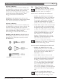
1
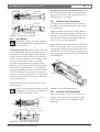
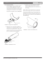
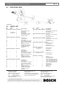
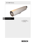
LTC 9385 Series
Instruction Manual
EN Outdoor Housings
LTC 9385 Series | Instruction Manual | Important Safeguards
EN | 2
Important Safeguards
1. Read, Follow, and Retain Instructions - All safety
and operating instructions should be read and
followed before operating the unit. Retain instructions
for future reference.
2. Heed Warnings - Adhere to all warnings on the unit
and in the operating instructions.
3. Attachments - Attachments not recommended by
the product manufacturer should not be used, as they
may cause hazards.
4. Installation Cautions - Do not place this unit on an
unstable stand, tripod, bracket, or mount. The unit
may fall, causing serious injury to a person and
serious damage to the unit. Use only manufacturerrecommended accessories, or those sold with the
product. Mount the unit per the manufacturer's
instructions. Appliance and cart combination should
be moved with care. Quick stops, excessive force, or
uneven surfaces may cause the appliance and cart
combination to overturn.
5. Cleaning - Unplug the unit from the outlet before
cleaning. Follow any instructions provided with the
unit. Generally, using a damp cloth for cleaning is
sufficient. Do not use liquid cleaners or aerosol
cleaners.
6. Servicing - Do not attempt to service this unit
yourself. Opening or removing covers may expose
you to dangerous voltage or other hazards. Refer all
servicing to qualified service personnel.
7. Damage Requiring Service - Unplug the unit from
the main AC power source and refer servicing to
qualified service personnel under the following
conditions:
• When the power supply cord or plug is damaged.
• If liquid has been spilled or an object has fallen
into the unit.
• If the unit has been exposed to water and/or
inclement weather (rain, snow, etc.).
• If the unit does not operate normally, when
following the operating instructions. Adjust only
those controls specified in the operating
instructions. Improper adjustment of other controls
may result in damage, and require extensive work
by a qualified technician to restore the unit to
normal operation.
• If the unit has been dropped or the cabinet
damaged.
• If the unit exhibits a distinct change in
performance, this indicates that service is needed.
8. Replacement Parts - When replacement parts are
required, the service technician should use
replacement parts specified by the manufacturer or
that have the same characteristics as the original part.
Unauthorized substitutions may result in fire,
electrical shock or other hazards.
9. Safety Check - Upon completion of servicing or
repairs to the unit, ask the service technician to
perform safety checks to ensure proper operating
condition.
Bosch Security Systems | January 26, 2005
10. Power Sources - Operate the unit only from the type
of power source indicated on the label. If unsure of
the type of power supply to use, contact your dealer
or local power company.
• For units intended to operate from battery power,
refer to the operating instructions.
• For units intended to operate with External Power
Supplies, use only the recommended approved
power supplies.
• For units intended to operate with a limited power
source, this power source must comply with
EN60950. Substitutions may damage the unit or
cause fire or shock.
• For units intended to operate at 24VAC, normal
input voltage is 24VAC. Voltage applied to the
unit's power input should not exceed 30VAC.
User-supplied wiring, from the 24VAC supply to
unit, must be in compliance with electrical codes
(Class 2 power levels). Do not ground the 24VAC
supply at the terminals or at the unit's power
supply terminals.
11. Coax Grounding - If an outside cable system is
connected to the unit, ensure that the cable system is
grounded. U.S.A. models only - Section 810 of the
National Electrical Code, ANSI/NFPA No.70,
provides information regarding proper grounding of
the mount and supporting structure, grounding of the
coax to a discharge unit, size of grounding
conductors, location of discharge unit, connection to
grounding electrodes, and requirements for the
grounding electrode.
12. Grounding or Polarization - This unit may be
equipped with a polarized alternating current line
plug (a plug with one blade wider than the other).
This safety feature allows the plug to fit into the
power outlet in only one way. If unable to insert the
plug fully into the outlet, try reversing the plug. If the
plug still fails to fit, contact an electrician to arrange
replacement of the obsolete outlet. Do not defeat the
safety purpose of the polarized plug.
Alternately, this unit may be equipped with a
3-wire grounding plug (a plug with a third pin, for
grounding). This safety feature allows the plug to fit
into a grounding power outlet only. If unable to insert
the plug into the outlet, contact an electrician to
arrange replacement of the obsolete outlet. Do not
defeat the safety purpose of the grounding plug.
13. Lightning - For added protection during a lightning
storm, or when this unit is left unattended and
unused for long periods of time, unplug the unit from
the wall outlet and disconnect the cable system. This
will prevent damage to the unit due to lightning and
power line surges.
EN | 3
LTC 9385 Series | Instruction Manual | Safety Precautions
For Indoor Product
1. Water and Moisture - Do not use this unit near
water - for example, in a wet basement, in an
unprotected outdoor installation or in any area
classified as a wet location.
2. Object and Liquid Entry - Never push objects of
any kind into this unit through openings, as they
may touch dangerous voltage points or short out
parts that could result in a fire or electrical shock.
Never spill liquid of any kind on the unit.
3. Power Cord and Power Cord Protection - For
units intended to operate with 230VAC, 50Hz,
the input and output power cord must comply
with the latest versions of IEC Publication 227 or
IEC Publication 245.
Power supply cords should be routed so they are
not likely to be walked on or pinched. Pay
particular attention to location of cords and plugs,
convenience receptacles, and the point of exit
from the appliance.
4. Overloading - Do not overload outlets and
extension cords; this can result in a risk of fire or
electrical shock.
For Outdoor Product
Power Lines - An outdoor system should not be
located in the vicinity of overhead power lines,
electric lights or power circuits, or where it may
contact such power lines or circuits. When
installing an outdoor system, extreme care should
be taken to keep from touching power lines or
circuits, as this contact might be fatal. U.S.A.
models only - refer to the National Electrical
Code Article 820 regarding installation of CATV
systems.
For Rack-mount Product
1. Ventilation - This unit should not be placed in a
built-in installation or rack, unless proper
ventilation is provided, or the manufacturer’s
instructions have been adhered to. The
equipment must not exceed its maximum
operating temperature requirements.
2. Mechanical Loading - Mounting of the
equipment in a rack shall be such that a
hazardous condition is not achieved due to
uneven mechanical loading.
Bosch Security Systems | January 26, 2005
Safety Precautions
CAUTION: TO REDUCE THE RISK OF
ELECTRIC SHOCK, DO NOT REMOVE COVER
(OR BACK). NO USER SERVICEABLE PARTS
INSIDE. REFER SERVICING TO QUALIFIED
SERVICE PERSONNEL.
This symbol indicates the presence of
uninsulated “dangerous voltage” within the
product’s enclosure. This may constitute a
risk of electric shock.
The user should consult the operating and
maintenance (servicing) instructions in the
literature accompanying the appliance.
Attention: Installation should be performed by
qualified service personnel only in accordance
with the National Electrical Code or applicable
local codes.
Power Disconnect. Units with or without
ON-OFF switches have power supplied to the
unit whenever the power cord is inserted into the
power source; however, the unit is operational
only when the ON-OFF switch is in the ON
position. The power cord is the main power
disconnect for all units.
EN | 4
LTC 9385 Series | Instruction Manual | Safety Precautions
Sicherheitshinweise
VORSICHT: UM EINEN ELEKTRISCHEN SCHLAG ZU
VERMEIDEN, IST DIE ABDECKUNG (ODER RÜCKSEITE) NICHT
ZU ENTFERNEN. ES BEFINDEN SICH KEINE TEILE IN DIESEM
BEREICH, DIE VOM BENUTZER GEWARTET WERDEN
KÖNNEN. LASSEN SIE WARTUNGSARBEITEN NUR VON
QUALIFIZIERTEM WARTUNGSPERSONAL AUSFÜHREN.
Das Symbol macht auf nicht isolierte „gefährliche Spannung"
im Gehäuse aufmerksam. Dies kann zu einem elektrischen
Schlag führen.
Der Benutzer sollte sich ausführlich über Anweisungen für
die Bedienung und Instandhaltung (Wartung) in den
begleitenden Unterlagen informieren.
Achtung! Die Installation sollte nur von qualifiziertem
Kundendienstpersonal gemäß jeweils zutreffender
Elektrovorschriften ausgeführt werden.
Unterbrechung des Netzanschlusses. Geräte mit oder ohne
Netzschalter haben Spannung am Gerät anliegen, sobald der
Netzstecker in die Steckdose gesteckt wird. Das Gerät ist jedoch
nur betriebsbereit, wenn der Netzschalter (EIN/AUS) auf EIN
steht. Wenn das Netzkabel aus der Steckdose gezogen wird, ist
die Spannungszuführung zum Gerät vollkommen unterbrochen.
Precauciones de Seguridad
PRECAUCIÓN: PARA DISMINUIR EL RIESGO DE DESCARGA
ELÉCTRICA, NO RETIRE LA CUBIERTA (NI LA PARTE
POSTERIOR). NO EXISTEN PIEZAS DE RECAMBIO EN EL
INTERIOR DEL EQUIPO. EL PERSONAL DE SERVICIO
CUALIFICADO SE ENCARGA DE REALIZAR LAS
REPARACIONES.
Sécurité
ATTENTION : POUR ÉVITER TOUT RISQUE D'ÉLECTROCUTION,
N'ESSAYEZ PAS DE RETIRER LE CAPOT (OU LE PANNEAU
ARRIÈRE). CET APPAREIL NE CONTIENT AUCUN COMPOSANT
SUSCEPTIBLE D'ÊTRE RÉPARÉ PAR L'UTILISATEUR. CONFIEZ
LA RÉPARATION DE L'APPAREIL À DU PERSONNEL QUALIFIÉ.
Ce symbole signale que le produit renferme une « tension
potentiellement dangereuse » non isolée susceptible de
provoquer une électrocution.
Ce symbole invite l'utilisateur à consulter les instructions
d'utilisation et d'entretien (dépannage) reprises dans la
documentation qui accompagne l'appareil.
Attention : l'installation doit exclusivement être réalisée par du
personnel qualifié, conformément au code national d'électricité
américain (NEC) ou au code d'électricité local en vigueur.
Coupure de l'alimentation. Qu'ils soient pourvus ou non d'un
commutateur ON/OFF, tous les appareils reçoivent de l'énergie une
fois le cordon branché sur la source d'alimentation. Toutefois,
l'appareil ne fonctionne réellement que lorsque
le commutateur est réglé sur ON. Le débranchement du cordon
d'alimentation permet de couper l'alimentation des appareils.
Veiligheidsmaatregelen
VOORZICHTIG: OPEN DE BEHUIZING OF DE ACHTERKANT
VAN HET APPARAAT NIET. ZO VERMINDERT U HET RISICO
OP ELEKTRISCHE SCHOKKEN. IN HET APPARAAT
BEVINDEN ZICH GEEN ONDERDELEN DIE U ZELF KUNT
REPAREREN. LAAT SERVICE EN ONDERHOUD UITVOEREN
DOOR GEKWALIFICEERD PERSONEEL.
Este símbolo indica que existen puntos de tensión peligrosos
sin aislamiento dentro de la cubierta de la unidad. Estos
puntos pueden constituir un riesgo de descarga eléctrica.
Dit symbool geeft aan dat er binnen in het apparaat
ongeïsoleerde, gevaarlijke spanning aanwezig is die mogelijk
elektrische schokken kan veroorzaken.
El usuario debe consultar las instrucciones de funcionamiento y
mantenimiento (reparación) en la documentación que se
suministra con el aparato.
De gebruiker dient de bedienings- en onderhoudsvoorschriften
te raadplegen in de documentatie die werd meegeleverd met
het apparaat.
Atención: la instalación la debe realizar únicamente personal
cualificado de conformidad con el National Electric Code o las
normas aplicables en su país.
Attentie: het apparaat mag alleen door gekwalificeerd personeel
worden geïnstalleerd. De installatie dient in overeenstemming
met de nationale elektrische richtlijnen of de van toepassing
zijnde lokale richtlijnen te worden uitgevoerd.
Desconexión de la alimentación. Las unidades con o sin
interruptores de encendido/apagado reciben alimentación
eléctrica siempre que el cable de alimentación esté conectado a
la fuente de alimentación. Sin embargo, la unidad sólo funciona
cuando el interruptor está en la posición de encendido. El cable
de alimentación es la principal fuente de desconexión de todas
las unidades.
Bosch Security Systems | January 26, 2005
Spanning uitschakelen. Apparatuur met of zonder
aan-uitschakelaar staat onder spanning zolang de stekker is
aangesloten op de wandcontactdoos. De apparatuur is uitsluitend
in werking als de aan-uitschakelaar aan staat. Het netsnoer is de
"hoofdschakelaar" voor alle apparatuur.
EN | 5
LTC 9385 Series | Instruction Manual | Safety Precautions
Medidas de Segurança
CUIDADO: PARA REDUZIR O RISCO DE CHOQUE
ELÉCTRICO, NÃO RETIRE A TAMPA (OU A PARTE
POSTERIOR). NO INTERIOR, NÃO EXISTEM PEÇAS QUE
POSSAM SER REPARADAS PELO UTILIZADOR. REMETA A
ASSISTÊNCIA PARA OS TÉCNICOS QUALIFICADOS.
Este símbolo indica a presença de "tensão perigosa" não isolada
dentro da estrutura do produto, o que pode constituir risco de
choque eléctrico.
O utilizador deve consultar as instruções de funcionamento
e manutenção (assistência) nos documentos que
acompanham o aparelho.
Atenção: a instalação deve ser executada apenas por técnicos
qualificados da assistência, de acordo com o código eléctrico
nacional ou os códigos locais aplicáveis.
Corte de corrente. As unidades com ou sem interruptores
ON-OFF (ligar/desligar) recebem corrente sempre que o fio de
alimentação está introduzido na fonte de alimentação; contudo, a
unidade apenas está operacional quando o interruptor ON-OFF
está na posição ON. O fio de alimentação destina-se a desligar a
corrente em todas as unidades.
Bosch Security Systems | January 26, 2005
Sicurezza
ATTENZIONE: PER RIDURRE IL RISCHIO DI SCOSSE
ELETTRICHE NON RIMUOVERE LA COPERTURA (O IL
PANNELLO POSTERIORE). L'UNITÀ NON CONTIENE
COMPONENTI INTERNI RIPARABILI DALL'UTENTE. PER
QUALSIASI INTERVENTO, RIVOLGERSI A PERSONALE
TECNICO QUALIFICATO.
Questo simbolo indica la presenza di "tensione pericolosa" non
isolata all'interno del contenitore del prodotto. Ciò comporta un
potenziale rischio di scosse elettriche.
Si consiglia di consultare le istruzioni operative e di
manutenzione (interventi tecnici) contenute nella
documentazione fornita con il dispositivo.
Attenzione: l'installazione deve essere effettuata esclusivamente
da personale tecnico qualificato in conformità con il National
Electrical Code o con le normative locali vigenti.
Scollegamento dell'alimentazione. Le unità dotate o sprovviste di
interruttori ON-OFF vengono alimentate quando si inserisce il
cavo nella presa dell'alimentazione. L'unità è tuttavia in funzione
solo quando l'interruttore ON-OFF si trova nella posizione ON. Il
cavo di alimentazione costituisce il dispositivo di scollegamento
dell'alimentazione principale per tutte le unità.
LTC 9385 Series | Instruction Manual | Contents
EN | 6
Table of Contents
Important Safeguards . . . . . . . . . . . . . . . . . . . . . . . . . . . . . . . . . . . . . . . . . . . . . . . . . . . . . . . . . . . . . . . . . . . . . .2
1.0
UNPACKING . . . . . . . . . . . . . . . . . . . . . . . . . . . . . . . . . . . . . . . . . . . . . . . . . . . . . . . . . . . . . . . . . . . . . .7
2.0
SERVICE . . . . . . . . . . . . . . . . . . . . . . . . . . . . . . . . . . . . . . . . . . . . . . . . . . . . . . . . . . . . . . . . . . . . . . . . .7
3.0
CARE AND MAINTENANCE . . . . . . . . . . . . . . . . . . . . . . . . . . . . . . . . . . . . . . . . . . . . . . . . . . . . . . . .7
4.0
DESCRIPTION . . . . . . . . . . . . . . . . . . . . . . . . . . . . . . . . . . . . . . . . . . . . . . . . . . . . . . . . . . . . . . . . . . . .7
4.1
Enclosure Rating . . . . . . . . . . . . . . . . . . . . . . . . . . . . . . . . . . . . . . . . . . . . . . . . . . . . . . . . . . . . . . . . . . . .7
5.0
INSTALLATION . . . . . . . . . . . . . . . . . . . . . . . . . . . . . . . . . . . . . . . . . . . . . . . . . . . . . . . . . . . . . . . . . . . .7
5.1
Model Designation . . . . . . . . . . . . . . . . . . . . . . . . . . . . . . . . . . . . . . . . . . . . . . . . . . . . . . . . . . . . . . . . . . .7
5.2
Tools Required . . . . . . . . . . . . . . . . . . . . . . . . . . . . . . . . . . . . . . . . . . . . . . . . . . . . . . . . . . . . . . . . . . . . . .8
5.3
Hardware Required . . . . . . . . . . . . . . . . . . . . . . . . . . . . . . . . . . . . . . . . . . . . . . . . . . . . . . . . . . . . . . . . . .8
5.4
Cable Requirements . . . . . . . . . . . . . . . . . . . . . . . . . . . . . . . . . . . . . . . . . . . . . . . . . . . . . . . . . . . . . . . . . .8
5.5
Disassembly and Mounting . . . . . . . . . . . . . . . . . . . . . . . . . . . . . . . . . . . . . . . . . . . . . . . . . . . . . . . . . . . .8
5.6
Camera/Lens Installation . . . . . . . . . . . . . . . . . . . . . . . . . . . . . . . . . . . . . . . . . . . . . . . . . . . . . . . . . . . . . .9
5.7
Camera/Lens Wiring . . . . . . . . . . . . . . . . . . . . . . . . . . . . . . . . . . . . . . . . . . . . . . . . . . . . . . . . . . . . . . . .10
5.8
Plug Insertion . . . . . . . . . . . . . . . . . . . . . . . . . . . . . . . . . . . . . . . . . . . . . . . . . . . . . . . . . . . . . . . . . . . . . .10
5.9
Video Coax Connection . . . . . . . . . . . . . . . . . . . . . . . . . . . . . . . . . . . . . . . . . . . . . . . . . . . . . . . . . . . . . .12
5.10 Lens Wiring . . . . . . . . . . . . . . . . . . . . . . . . . . . . . . . . . . . . . . . . . . . . . . . . . . . . . . . . . . . . . . . . . . . . . . .13
5.11 Camera/Lens Orientation . . . . . . . . . . . . . . . . . . . . . . . . . . . . . . . . . . . . . . . . . . . . . . . . . . . . . . . . . . . .13
5.12
Camera/Lens Adjustment . . . . . . . . . . . . . . . . . . . . . . . . . . . . . . . . . . . . . . . . . . . . . . . . . . . . . . . . . . . .13
5.13 Final Assembly . . . . . . . . . . . . . . . . . . . . . . . . . . . . . . . . . . . . . . . . . . . . . . . . . . . . . . . . . . . . . . . . . . . . .14
6.0
EXPLODED VIEW . . . . . . . . . . . . . . . . . . . . . . . . . . . . . . . . . . . . . . . . . . . . . . . . . . . . . . . . . . . . . . . .16
7.0
PARTS LIST . . . . . . . . . . . . . . . . . . . . . . . . . . . . . . . . . . . . . . . . . . . . . . . . . . . . . . . . . . . . . . . . . . . . . .16
Bosch Security Systems | January 26, 2005
EN | 7
LTC 9385 Series | Instruction Manual | Unpacking
1.0
UNPACKING
This electronic equipment should be unpacked and
handled carefully.
Check for the following items:
Quantity
Part Description
1
1/4-20 x 3/8in. BHCS (Button Head Cap
Screw)
1
1/4-20 x 1/2in. BHCS
1
1/4-20 x 5/8in. BHCS
1
1/4-20 x 3/4in. BHCS
1
1/4-20 x 7/8in. BHCS
4
3.2mm (0.125in.) plastic spacer
4
0.4mm (0.016in.) plastic spacer
2
Nylon bushings
1
3/8in. NPT plug
1
Small flex fitting
2
Pull Seals
2
Large flex fitting
3
Cable ties
If an item appears to have been damaged in shipment,
replace it properly in its carton and notify the shipper.
If any items are missing, notify your Bosch Security
Systems Inc. Sales Representative or Customer Service.
3.0
CARE AND MAINTENANCE
There are no moving parts in this unit. Regularly
scheduled maintenance will help prolong the
operational life of this unit. Clean the viewing window
as needed with a mild, nonabrasive detergent in water
and a soft cloth.
4.0
DESCRIPTION
The LTC 9385 Series of environmental housings are
attractive aluminum enclosures designed for outdoor
CCD camera installations.
4.1
Enclosure Rating
4.1.1
NEMA-3R and IP54
The LTC 9385 Series housings include a breather hole in
the front face plate. The breather hole prevents the
accumulation of moisture inside the housing when
installed in areas of high humidity. With the breather
hole open, the LTC 9385 Series housings meet the
enclosure rating requirements of NEMA-3R and IP54.
The shipping carton is the safest container in which the
unit may be transported. Save it for possible future use.
4.1.2 NEMA-4 and IP65
For installations requiring an enclosure rating of
NEMA-4 or IP65, the breather hole must be plugged
using the pull seal (Part No. 315 2569 001) provided in
the hardware kit. Refer to Final Assembly under
INSTALLATION for proper installation.
2.0
5.0
SERVICE
If the unit ever needs repair service, the customer
should contact the nearest Bosch Security Systems, Inc.
Service Center for return authorization and shipping
instructions.
INSTALLATION
This installation should be made by a qualified
service person and conform to all local codes.
5.1
Model Designation
Model
Rated
Service Centers
No.
Input
USA
Phone:
800-366-2283 or 717-735-6638
fax:
800-366-1329 or 717-735-6639
CCTV Spare Parts
Phone:
800-894-5215 or 408-956-3853 or 3854
fax:
408-957-3198
e-mail:
[email protected]
Canada
Phone:
514-738-2434
Europe, Middle East & Asia Pacific Region
Phone:
32-1-440-0711
For additional information, see www.boschsecurity.com.
LTC 9385/60
115VAC, 50/60Hz
108 to 132
LTC 9385/20
24VAC, 50/60Hz
21.6 to 26.4 50W
LTC 9385/50
230VAC, 50/60Hz
207 to 253
Bosch Security Systems | January 26, 2005
1
Range
Power
Consumption1
50W
50W
Heater requires 40 watts.
Do Not Exceed 30VAC Input on 24VAC models.
Operation above 30VAC violates low voltage operation
(Class 2 Specifications). Normal operation is 24VAC.
Maximum Camera/Lens Size: Accepts cameras
up to 102W x 71H mm (4.0 x 2.8in.), lenses up to
102W x 92H mm (4.0 x 3.6in.), and camera/lens
combinations up to 345L mm (13.6in.).
EN | 8
LTC 9385 Series | Instruction Manual | Installation
5.2
•
•
•
•
•
•
•
•
5.3
•
•
•
5.4
Input Power Cord - European
Tools Required
Flat blade screwdriver
Phillips head screwdriver
M7 (7mm) hex wrench or socket
M3 (3mm) hex wrench
M4 (4mm or 5/32in.) hex wrench
M8 (8mm or 5/16in.) hex wrench
Adjustable wrench
Wire cutter/stripper/crimper tool
Cable Type
H05RN-F3G0.75 and
H05RN-F3G1.00
Cable Size
Outside diameter between 4.3mm
and 11.9mm (0.170in. and 0.470in.)
Cable Shape
Round
Conductors
3 conductor version and
2 conductor version
Agency Rating
VDE
Environmental
Outdoor rated
Hardware Required
Sources
Olflex 1600252
Olflex 1600253
M6 screws (X3) or 1/4in. screws (X3)
M6 nuts (X3) or 1/4in. nuts (X3)
M6 lock washers (X3) or
1/4in. lock washers (X3)
Cable Requirements
Video Transmission (Coaxial)
Cable Type
RG-59/U (Runs < 1000ft)
RG-11/U (Runs < 2000ft)
Cable Size
Outside diameter between 4.6mm
and 7.9mm (0.181in. and 0.312in.)
Cable Shape
Round
Shield
≥ 93% Braided Copper Shield
Center Conductor
Stranded Copper Center
DC Resistance
≥ 15Ω/1000ft (RG-59/U)
≥ 6Ω/1000ft (RG-11/U)
Cable Impedence
75Ω
Agency Rating
UL
Environmental
Outdoor rated
Temperature Rating
≥ 80 °C (176 °F)
Sources
Belden 9259
Belden 9238
Lens Control Cable
Cable Type
Jacketed Multiconductor Cable
Cable Size
Outside diameter between 4.3mm
and 11.9mm (0.170in. and 0.470in.)
Cable Shape
Round
Shield
Overall shielding
Conductors
Stranded 20 to 16 AWG wire
No. of Conductors
4 and 8
Conductor Insulation
Color coded
Sources
Belden 9552
Belden 9554
5.5
Disassembly and Mounting
1. Detach the hardware kit from the housing.
2. Use a M7 hex wrench or socket to remove the
two M4 screws from the housing cover. Save all
hardware, which will be needed in reassembly.
See FIGURE 1.
Input Power Cord - North American
Cable Type
SJTOW-A Rated
Cable Size
Outside diameter between 4.3mm
and 11.9mm (0.170in. and 0.470in.)
Cable Shape
Round
Conductors
3 conductor version and
2 conductor version
Agency Rating
UL/C.S.A., UL VW-1
Environmental
Outdoor rated
Temperature Rating
105 °C
Voltage Rating
300 V
Sources
Belden 19506
Belden 19509
Northwire 573939
Bosch Security Systems | January 26, 2005
M4 Screws
FIGURE 1 Removing the M4 Cover Screws
EN | 9
LTC 9385 Series | Instruction Manual | Installation
3. Remove the cover from the base assembly by
grasping the cover and gently pulling forward.
Do not remove the safety cable from the cover
or the base assembly. See FIGURE 2.
Cover
5.6
Camera/Lens Installation
Place the camera/lens combination onto the rail
assembly.
Fixed Lens Cameras: Position the camera/lens so that
the lens is positioned over the heater but not past it.
Secure the camera to the rail assembly with the
1/4-20 x 3/8in. BHC screw, a nylon bushing, and a
0.4mm (0.016in.) plastic spacer. Place the nylon
bushing over the screw and slide both between the
rails through the front cut-out section. Slide the spacer
over the screw so it is positioned in-between the rails
and the camera. See FIGURE 4.
Base Assembly
FIGURE 2 Removing the Cover
4. Attach the housing to an appropriate mount or
pan/tilt. Use the instructions provided with the
mount or pan/tilt. The base assembly has three
clearance holes for mounting. Use three M6
screws and nuts or three 1/4in. screws and nuts
(not provided). Lock washers are required (not
provided). Rotating the rail assembly will allow
access to the mounting holes. This can be
accomplished by loosening the three M4 screws.
See also Camera/Lens Orientation. It will be easier
to mount the base before installing the camera,
but it may be mounted anytime during the
installation process. See FIGURE 3.
Rail Assembly
M4 Screws
FIGURE 4 Mounting a Fixed Lens Camera
Zoom Lens Cameras: Position the camera/lens so
that the lens is positioned over the heater but not past
it. The camera/lens combination will determine the
screws and spacers that will be needed. Secure the
camera and lens to the rail assembly with 1/4-20 BHC
screws, nylon bushings, and plastic spacers. Place the
nylon bushings over the screws and slide both between
the rails through the front cut-out section. Slide the
spacer over the screw so it is positioned in-between the
rails and the camera. There are four large spacers
(3.2mm) and four small spacers (0.4mm) provided.
See FIGURE 5.
Camera
Mounting Holes
FIGURE 3 Mounting the Base Assembly
Spacer
Spacer
Bushing
Rails
Screw
FIGURE 5 Mounting a Zoom Lens Camera
Bosch Security Systems | January 26, 2005
EN | 10
LTC 9385 Series | Instruction Manual | Installation
5.7
Camera/Lens Wiring
5.8
WARNING: Only use the cables specified
under INSTALLATION, Cable Requirements for
wiring of all cameras and lenses.
If no lens control or feed-through wiring will be used,
install the 3/8in. NPT plug provided. Remove the
liquid-tight fitting and insert the plug in the small
bottom center 3/8in. NPT hole. Use a 8mm or a
5/16in. hex wrench to tighten securely. Failure to do so
will result in water damage to all electronic parts. See
FIGURE 7.
5.7.1 Liquid-Tight Fittings
The dual-male threaded portion of the two 1/2in. NPT
and one 3/8in. NPT liquid-tight fittings are preinstalled
in the rear of the base assembly. If possible, do not
remove or loosen these parts. They have been installed
to a specified torque to prevent water damage. The
small 3/8in. NPT fitting will accept cables with
diameters from 4.6mm (0.181in.) to 7.9mm (0.31in.).
The two large 1/2in. NPT fittings will accept cables
with diameters from 4.3mm (0.170in.) to 11.9mm
(0.470in.). See FIGURE 6.
Plug Insertion
3/8in. NPT Plug
Be sure to securely tighten all fittings to ensure
a liquid-tight seal. Not doing so could damage
the camera, the housing, or both.
If a sealant will be used, be sure it is a neutral cure
type. Sealants that release acetic acid may harm
camera electronics.
If it is necessary to use PG type conduit, a TC9385PG
kit is available. The TC9385PG kit contains a wire
grip with two PG11 and one PG7 tapped holes. The
NPT wire grip is removed and replaced with the PG
version.
Wire Grip
Dual Male
Portion
Seal Glands
Flexible Portion
FIGURE 6 Liquid-tight Fitting Assembly
Bosch Security Systems | January 26, 2005
FIGURE 7 3/8in. NPT Plug Insertion
5.8.1 Supply Power Connections
The LTC 9385 Series housings offer the user one of three
voltage configurations. The suffix to the housing model
number will determine the supply voltage required.
Any camera installed in the LTC 9385 Series housings
must be of the same voltage type as the housing. The
integral heater/defogger also requires the same voltage as
the housing. These housings do not contain step down or
isolation transformers. See the Model Designation chart
for suffixes and supply voltages required.
Power connection into the housings is to be supplied
through a minimum type UL Standard SJ cord
acceptable for outdoor use. Installation must conform
to applicable NEC and local codes. Use the
Recommended Maximum Cable Lengths chart
below for proper wire size selection.
EN | 11
LTC 9385 Series | Instruction Manual | Installation
Recommended Maximum Cable Lengths
Models
Wire Size
Distance
mm2
1.5
2.5
4
AWG
16
14
12
-2 (24 VAC)
0.5
0.5
1
1.5
2.5
22
20
18
16
14
10
15
25
40
70
30
50
80
120
210
-4 (230 VAC)
1.5
2.5
4
16
14
12
4000
6400
10000
13000
21000
32800
-1 (115 VAC)
meters
1000
1600
2500
feet
3280
5250
8200
1. Use the liquid-tight fitting on the left of the
housing to route the power supply cord into the
housing.
2. Allow enough cord for connection to the
terminal block; approximately, 130mm (5in.).
Strip no less than 6mm (0.24in.) and no more
than 8mm (0.31in.) of insulation away from the
wires making sure not to nick the wires.
3. A screw/terminal lug is provided for securing a
safety ground. To attach the safety grounding
wire of the power cord (green 115volt,
green/yellow 230volt), first unscrew the terminal
lug and strip and crimp the grounding wire into
the lug. Next, reattach the terminal lug to the
rail assembly using the M4 x 10 screw and lock
washer provided. See FIGURE 8.
FIGURE 8 Securing the Ground Wire
Bosch Security Systems | January 26, 2005
4. Connect both the line and neutral wires of the
power cord to the terminal block. Make sure
the line and neutral wires are connected to the
correct positions on the terminal block that are
across from the appropriate colored wire. See
FIGURE 9.
FIGURE 9 Attaching Line and Neutral Wires
5. Pull any excess cord through the liquid-tight
fitting and tighten the flex fitting to 8.5N-m to
9.0N-m (75in. lb to 80in. lb). This torque rating
is approximately 1 to 1 1/2 turns past the point
that the fitting starts to grip the cord. Failure to
do so will result in water damage to all
electronic parts. Use a tie wrap (included) to
provide strain relief on the power cord at the
exit point (inside the unit).
Securely tighten all fittings to ensure a liquidtight seal. Not doing so could damage the
camera, the housing, or both.
5.8.2 Camera Power Connections
LTC 9385/60 Housings
These housings are to be connected to 115VAC, and
are designed for use where site power is 115volts. The
LTC 9385/60 housings should only be used with
115volt cameras. The integral heater/defogger
requires 115volts. The housing is shipped with the
heater/defogger connected to the terminal block.
Installing a 115 volt camera into the LTC 9385/60
housing simply requires the camera's line cord to be
plugged into the NEMA 5-15R receptacle provided.
See FIGURE 10.
EN | 12
LTC 9385 Series | Instruction Manual | Installation
LTC 9385/20 Housings
These housings are to be connected to 24VAC, and
are designed for use where site power is 24volts. The
LTC 9385/20 housings should only be used with
24volt cameras. The integral heater/defogger requires
24volts. The housing is shipped with the heater/
defogger connected to the terminal block.
Installing a 24 volt camera into the LTC 9385/20
housing simply requires the two flying leads be attached
to the camera's terminal block. See FIGURE 10.
LTC 9385/50 Housings
These housings are to be connected to 230VAC, and
are designed for use where site power is 230volts. The
LTC 9385/50 housings should only be used with
230volt cameras. The integral heater/defogger requires
230volts. The housing is shipped with the
heater/defogger connected to the terminal block.
Installing a 230 volt camera into the LTC 9385/50
housing simply requires the camera's line cord to be
plugged into the Schuko inline receptacle provided.
See FIGURE 10.
5.9
Video Coax Connection
WARNING: Only use the cables specified
under INSTALLATION, Cable Requirements for
wiring of the video coax connection.
If lens control or feed-through wires will be used:
1. Install the long flexible portion of the small
liquid-tight fitting on the video coax cable and
pull the cable through the small fitting on the
rear end of the base assembly. The fitting will
accept cables with diameters from 4.6mm
(0.181in.) to 7.9mm (0.312in.). See FIGURE 11.
2. Attach a BNC connector to the coax and connect
it to the camera. Pull any excess cable through
the liquid-tight fitting and tighten the flex fitting
to 4.0N-m to 4.5N-m (35in. lb to 40in. lb). This
torque rating is approximately 1 to 1 1/2 turns
past the point that the fitting starts to grip the
cable. Failure to do so will result in water
damage to all electronic parts. Use a tie wrap
(included) to provide strain relief on the video
cable at the exit point (inside the unit).
Be sure to securely tighten all fittings to ensure
a liquid-tight seal. Not doing so could damage
the camera, the housing, or both.
If no lens control or feed-through wires will be used:
1. Install the long flexible portion of a large
liquid-tight fitting on the video coax cable and
pull the cable through the large right fitting on
the rear end of the base assembly. Refer to
FIGURES 11 and 12.
FIGURE 10 Camera Connections
2. Attach a BNC connector to the coax and
connect it to the camera. Pull any excess cable
through the liquid tight fitting and tighten the
flex fitting to 8.5N-m to 9.0N-m (75in. lb to
80in. lb). This torque rating is approximately
1 to 1 1/2 turns past the point that the fitting
starts to grip the wire. Failure to do so will
result in water damage to all electronic parts.
Use a tie wrap (included) to provide strain relief
on the video cable at the exit point (inside the
unit).
Be sure to securely tighten all fittings to
ensure a liquid-tight seal. Not doing so could
damage the camera, the housing, or both.
Bosch Security Systems | January 26, 2005
EN | 13
LTC 9385 Series | Instruction Manual | Installation
BNC Connector
Video Coax Cable
CCD Camera
5.11
Small Fitting
Video Coax Cable
CCD Camera
BNC Connector
Small Fitting
FIGURE 11 Video Coax Connection
5.10
If using a pan/tilt with a feed-through cable, insert
the camera/lens function cable in through the right
fitting at the rear of the cradle. Wire the functions as
described above, or as needed.
Lens Wiring
WARNING: Only use the cables specified
under INSTALLATION, Cable Requirements for
wiring of the lens.
If installing a zoom lens, insert the lens control cable
with installed flexible fitting in through the fitting on
the right rear of the base assembly. Attach the lens
wiring to the lens mating connector and connect it to
the lens. If mating connector is not available, connect
directly to the lens cable. Pull any excess cable
through the liquid-tight fitting and tighten the flex
fitting to 8.5N-m to 9.0N-m (75in. lb to 80in. lb). This
torque rating is approximately 1 to 1 1/2 turns past
finger-tight, depending on the size of the wire. Failure
to do so will result in water damage to all electronic
parts. Use a tie wrap (included) to provide strain relief
on the lens control cable at the exit point (inside the
unit). See FIGURE 12.
Camera/Lens Orientation
A unique feature of the LTC 9385 Series housing is
the ability to rotate the mounting base 360º around
the rail assembly.
Simply loosen the three M4 screws with a M3 hex
wrench. Rotate the base assembly around the rail
assembly to any position and tighten the M4 screws.
It is preferable to keep the rail assembly under the
camera, not over it. See FIGURE 13.
NOTE: Make sure the breather hole is located at the
bottom of the housing. If it is not, remove both front
retaining rings and the face plate. Orient them so the
breather hole is located at the bottom and the gaps in
the retaining rings are centered over the breather hole.
See FIGURE 20.
Base Assembly
M4 Screws
NOTE: See specification on the lens cord for correct
plug connection.
Be sure to securely tighten all fittings to ensure
a liquid-tight seal. Not doing so could damage
the camera, the housing, or both.
CCD Camera
Lens Control Cable
Lens Control Connectors
CCD Camera
FIGURE 12 Lens Control Cable Wiring
Bosch Security Systems | January 26, 2005
FIGURE 13 Base Assembly Rotation
5.12
Camera/Lens Adjustment
Before final assembly of the cover over the rest of
housing, verify camera and lens operation. Adjust
camera/lens as necessary. See individual camera
instructions.
EN | 14
LTC 9385 Series | Instruction Manual | Installation
5.13
Final Assembly
5.13.1 Pull Seal Installation
If the breather hole is open, do NOT mount the
housing in a position where the front face
plate is pointed upward.
To maintain enclosure protection ratings of NEMA-4
and IP65, the pull seal (provided in the hardware kit)
must be installed in the front face plate. It is
recommended that the pull seal be installed in a cool,
dry environment to prevent trapping moisture inside
the housing. See FIGURE 14.
NOTE: Pull seal installation allows the housing’s front
end to be pointed upward.
Front
Face
Plate
3. Insert the long end of the pull seal into the
breather hole starting from the front side of the
face plate. See FIGURE 16.
Housing
Face Plate
Pull Seal
FIGURE 16 Inserting the Pull Seal
4. Reach into the housing and grip the pull seal’s
long end from the back of the front face plate.
Steadily pull the long end until the head of the
pull seal is flat against the front of the end cap.
See FIGURE 17.
NOTE: The Pull Seal’s long end will stretch when
pulled through the breather hole.
Breather Hole
Housing (cut away)
FIGURE 14 Breather Hole
Proper installation of the pull seal is as follows:
1. If the housing assembly is not already removed
from the base assembly, do so now; see the
Disassembly and Mounting section at the beginning
of these instructions.
2. Obtain a rubber pull seal from the hardware kit
(Part Number 315 2569 001). An extra pull seal
is also provided. See FIGURE 15.
FIGURE 15 Pull Seal
Bosch Security Systems | January 26, 2005
Grip and Pull
FIGURE 17 Installing the Pull Seal
EN | 15
LTC 9385 Series | Instruction Manual | Installation
5.13.2 Housing Assembly
1. The lens support screw is provided to support
the rail assembly. Adjustment will only be
necessary if the rail assembly is rotated at angle
other than horizontal. If the screw head is not
touching the cover when the cover is installed,
loosen the screw until it does. See FIGURE 18.
3. Align the cover holes with the base assembly
holes and replace the two M4 screws and
washers. This secures the cover onto the rest of
the housing.
NOTE: Make sure the breather hole is located at the
bottom of the housing. If it is not, remove both front
retaining rings and the face plate. Orient them so the
breather hole is located at the bottom and the gaps in
the retaining rings are centered over the breather hole.
See FIGURE 20.
Front
Face
Plate
Lens Support Screw
FIGURE 18 Support Screw Adjustment
Retaining Ring
2. Replace the cover onto the base assembly by
grasping the cover and gently pushing it over the
end cap and o-ring. Make sure the o-ring is not
pinched. The safety cable can be routed between
the cover and the base. See FIGURE 19.
Cover
Base Assembly
End Cap
FIGURE 19 Replacing the Cover
Bosch Security Systems | January 26, 2005
Breather Hole (centered)
FIGURE 20 Location of the Breather Hole
EN | 16
LTC 9385 Series | Instruction Manual | Exploded View
6.0
EXPLODED VIEW
FIGURE 21
7.0
PARTS LIST
Ref
Drawing
No.
No.
Qty.
Part Description
Mounting Base Assembly Kit - 315 2805 001
1
1
Mounting Base Assembly
2
1
Wire Grip Cap
3
315 2298 900
1
EP O-ring 037
5
315 2327 900
2
EP O-ring 248
17
7
M4 Internal Star Lock Washer
21
3
M4 Hex Head Cap Screw
22
3
M4 Fender Washer
115VAC Rail Assembly Kit - 315 2806 001
6
1
7
1
8
1
16
3
17
7
18
1
19
20
23
--
-
2
3
3
1
24VAC Rail Assembly Kit - 315 2807 001
6
1
7
1
8
1
16
3
17
7
18
1
19
20
23
-
2
3
3
230VAC Rail Assembly Kit - 315 2808 001
6
1
7
1
8
1
16
3
17
7
18
1
19
20
23
--
-
2
3
3
1
Terminal Block
Rail-back Weldment
Ground Spring
M4 x 16 Low Socket Cap Screw
M4 Internal Star Lock Washer
#6-32 x 5/8in. Bosch Flat Head
Screw
#8 Ring Tongue Terminal
M3 Philips Pan Head Screw
M4 Philips Pan Head Screw
115 VAC NEMA 5-15R
Receptacle
Terminal Block
Rail-back Weldment
Ground Spring
M4 x 16 Low Socket Cap Screw
M4 Internal Star Lock Washer
#6-32 x 5/8in. Bosch Flat Head
Screw
#8 Ring Tongue Terminal
M3 Philips Pan Head Screw
M4 Philips Pan Head Screw
Terminal Block
Rail-back Weldment
Ground Spring
M4 x 16 Low Socket Cap Screw
M4 Internal Star Lock Washer
#6-32 x 5/8in. Bosch Flat Head
Screw
#8 Ring Tongue Terminal
M3 Philips Pan Head Screw
M4 Philips Pan Head Screw
230VAC Schuko In-Line
Receptacle
Americas
Bosch Security Systems
130 Perinton Parkway
Fairport, New York, 14450, USA
Phone: +1 (585) 223 4060
Fax:
+1 (585) 223 9180
E-mail: [email protected]
www.boschsecurity.us
Ref
Drawing
No.
No.
Qty.
Part Description
115VAC Heater-Bracket Assembly Kit - 315 2809 001
9
1
115VAC Heater - Bracket Assembly
-1
M3 x 20 Screw
-2
Rivet, 5/32in. x 0.415in.
24VAC Heater-Bracket Assembly Kit - 315 2810 001
9
1
24VAC Heater - Bracket Assembly
-1
M3 x 20 Screw
-2
Rivet, 5/32in. x 0.415in.
230VAC Heater-Bracket Assembly Kit - 315 2811 001
9
1
230VAC Heater - Bracket Assembly
-1
M3 x 20 Screw
-2
Rivet, 5/32in. x 0.415in.
Two-Eye Cable Assembly Kit - 315 2812 001
10
1
2 Eye Cable Assembly
13
1
M6 Flat Washer
14
2
M6 Thin Hex Nut
15
2
M6 Serrated Lock Washer
Faceplate Kit - 315 2813 001
4
315 2300 900 2
5
315 2327 900 1
12
1
24
2
Retaining Ring 500
EP O-ring 248
Faceplate
Rubber Pull Seal
Housing Assembly - 315 2814 001
4
315 2300 900 2
11
1
Retaining Ring 500
Housing Assembly
Hardware Kit - 315 2348 001
-3
-4
-4
-1
-1
-1
-1
-1
-1
-1
-2
24
2
-2
Cable Tie
3.2mm Plastic Spacer
0.4mm Plastic Spacer
1/4-20 x 3/8in. Button Head Screw
1/4-20 x 1/2in. Button Head Screw
1/4-20 x 5/8in. Button Head Screw
1/4-20 x 3/4in. Button Head Screw
1/4-20 x 7/8in. Button Head Screw
3/8in. NPT Plug
Small Flex Fitting
Large Flex Fitting
Pull Seal
Nylon Bushing
Europe, Middle East, Africa
Bosch Security Systems B.V.
P.O. Box 80002
5600 JB Eindhoven, The Netherlands
E-mail: [email protected]
http://www.boschsecurity.com
© 2005 Bosch Security Systems GmbH
3935 890 06612 05-04 | Updated January 26, 2005 | Data subject to change without notice.
Asia-Pacific
Bosch Security Systems Pte Ltd
38C Jalan Pemimpin
Singapore 577180, Singapore
Phone: +65 319 3488
Fax:
+65 319 3499
E-mail: [email protected]
http://www.boschsecurity.com