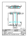
1
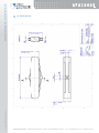
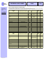
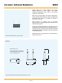
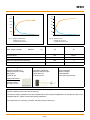
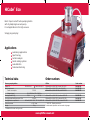
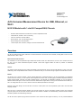
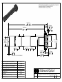
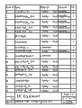
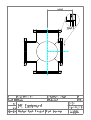
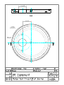
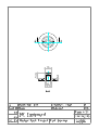
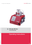
ANNEXES ANNEX A: COMPONENT DATASHEET 1 2 3 4 5 Force system 1.1 APA1000L Piezoelectric actuato 1.2 CA 45 Compact stand alone amplifier 1.3 U9B Load cell Heating system 2.1 SITOP flexi Power supply 2.2 MSH Ceramic infrared radiators Vacuum system 3.1 HiCube Eco Turbopump 3.2 PKR 251 Compact fullrange gauge 3.3 RS 428-477 Power supply National Instruments equipment 4.1 NI cDAQ-9174 USB chassis 4.2 NI 9219 Universal measurement device 4.3 NI 9263 Analog output 4.4 NI 9211 Thermocouple input Image acquisition 5.1 BASLER acA2500-um Camera 5.2 Edmund Optics 63743 Telecentric lens TABLE OF STANDARD PROPERTIES OF USE AND MEASUREMENT NON CONTRACTUAL PICTURE www.cedrat-technologies.com | [email protected] APA1000L The properties defined in the table below, are set up according to the technical conditions of use and measurement. These properties are warranted within their variation range and in compliance with the standard technical conditions of use. PROPERTIES STANDARD TECHNICAL CONDITIONS Notes Max. no load displacement Quasistatic excitation, blocked-free NOMINAL VALUES UNIT MIN. VALUES MAX. VALUES - - - - µm 897 717 1058 Blocked force Quasistatic excitation, blocked-free N 292.3 248.4 336.1 Stiffness Quasistatic excitation, blocked-free N/µm 0.326 0.261 0.36 Resonance frequency (free-free) Harmonic excitation, free-free, on the admittance curve Hz 1305 1109 1436 ms 0.38 0.34 0.44 Hz 254 216 279 ms 1.97 1.77 2.26 µF 40.00 36.00 52.00 Response time (free-free) Resonance frequency (blocked-free) Harmonic excitation, blocked-free, on the admittance curve Response time (blocked-free) Capacitance Quasistatic excitation, free-free, on the admittance curve Max. no load displacement at resonance Max. harmonic excitation, free-free µm p-p 404 323 484 Max. voltage at resonance Max. harmonic excitation, free-free Vrms 9.00 7.20 10.80 80.38 Force limit (0-pk) Max. harmonic excitation, free-free Resolution Quasistatic excitation Height (in actuation direction) N 73.07 58.46 nm 9 - - mm 35.00 34.90 35.10 145.10 Length mm 145.00 144.90 Width (excl. wedge & wires) mm 10.00 9.95 10.05 Width (incl. wedge & wires) mm 16.00 15.00 17.50 Mass g 190.0 - - Standard mechanical interface 2 flat surfaces 1*2.5 mm² with a Ø 0.8 mm hole - - - - Standard electrical interface 2 single Cu wires 80 mm long with Ø 1 banana plug - - - - PROPERTIES STANDARD TECHNICAL CONDITIONS OF USE AND MEASUREMENT Free-free : Blocked-free : Quasistatic excitation : Harmonic excitation : Max. harmonic excitation : Displacement measurement : Admittance measurement : Environment : The actuator is not fixed The actuator is fixed to a mechanical support assumed infinitely stiff AC voltage between –20 and 150 V at 1 Hz Voltage of 0.5 Vrms, sinusoidal mode from 0 to 100 kHz Voltage defined by the measurement of max. displacement, sinus at resonance frequency Laser interferometer, capacitive displacement sensor HP 4194 A or Cypher C60 electrical impedance analyser Ambient temperature (15-25°C) and dry air (Humidity < 50 % rH) Any technical conditions of use, different from those defined above, can lead to temporary or definitive alterations of properties. Thank you to contact CEDRAT TECHNOLOGIES before using actuators under non standard technical conditions. FACTORY TESTS CARRIED OUT Test 1 : Electrical admittance vs. Frequency, free-free Test 2 : Displacement vs. input voltage Copyright © CEDRAT TECHNOLOGIES | 03/2014 OPTIONAL EXTRA FACTORY TESTS Test 3 : Gain and linearity of the sensor Test 4 : Step response in closed loop Test 5 : Stability in closed loop OPTIONAL MECHANICAL INTERFACE [ FI ] Flat Interface [ FF ] Free-free Interface [ H ] Flat Interface with hole [ SI ] Specific interface [ TH ] Flat Interface with threaded hole AVAILABLE OPTIONS [ SG ] Strain gauges [ NM ] Non-magnetic [ ECS ] Eddy current displacement sensor [ VAC ] Vacuum [ SV ] Specific version / Customization CEDRAT TECHNOLOGIES • 59 Chemin du Vieux Chêne • Inovallée • 38246 MEYLAN Cedex France Tel. : +33 (0)4 56 58 04 00 • Fax : +33 (0)4 56 58 04 01 www.cedrat-technologies.com | [email protected] Copyright © CEDRAT TECHNOLOGIES | 03/2014 APA1000L 2D CONFIGURATION CEDRAT TECHNOLOGIES • 59 Chemin du Vieux Chêne • Inovallée • 38246 MEYLAN Cedex France APA40SM Tel. : +33 (0)4 56 58 04 00 • Fax : +33 (0)4 56 58 04 01 TECHNICAL DATA SHEET CEDRAT TECHNOLOGIES 15 chemin de Malacher ZIRST 38246 MEYLAN Cedex France Tel. : +33 4 76 90 50 45 Fax : +33 4 56 38 08 30 http://www.cedrat.com [email protected] CA45 v3.3 TABLE OF STANDARD PROPERTIES OF USE AND MEASUREMENT The properties defined in the table below, are set up according to the technical conditions of use and measurement. These properties are warranted within their variation range and in compliance with the standard technical conditions of use. Properties CA45 Standard technical conditions Unit Notes Nominal values Max. values - Function Standalone voltage amplifier Cooling Natural convection Thermal Overcurrent Overvoltage Protection Main voltage Standard main supply VAC 230 190.0 250.0 Main frequency Standard main supply Hz 50 45.0 65.0 Min. input voltage Standard environment V -1.2 -1.5 -1.2 Max. input voltage Standard environment V 7,7 7.7 7.9 Min. output voltage Standard environment V -20 -19.0 -22.0 Max. output voltage Standard environment V 150 145.0 160.0 Gain Standard environment V/V 20 19.0 21.0 A 0.036 0.027 0.045 µF 400 360.0 440.0 dB 85 80.0 90.0 Hz 30000 27000 33000 Hz 62 61.6 67.8 kOhms 10 9.5 10.5 g 1200 - - mm 12F wide, 3H high Unit Nominal values Min. values Max. values Max. output current Max. output load capacitance Signal to noise ratio Noise measurement conditions Unloaded output bandwith (-3dB) Loaded Output bandwidth (-3dB) Standard load Input impedance Mass Dimensions Option UC45 Standard technical conditions Notes Option on amplifier board Numerical servo controller Function Size mm Max. number of control channels 50*70 1 per channel Sampling frequency Hz 10000 A/D converters 16 bit @ +/-10V D/A converters 16 bit @ +/-10V Computer interface USB Optional link Corrector filter cells SPI 2nd order low-pass or stop-band filter @ [150 2000]Hz *Bandwidth settled according to your specifications; by default 1 Hz. CA45_GB_v3.3.doc Min. values Selectable by the GUI HDPM45 TECHNICAL DATA SHEET CEDRAT TECHNOLOGIES 15 chemin de Malacher ZIRST 38246 MEYLAN Cedex France Tel. : +33 4 76 90 50 45 Fax : +33 4 56 38 08 30 http://www.cedrat.com [email protected] Option SG Standard technical conditions CA45 Unit v3.3 Nominal values Notes Option on amplifier board Function Strain Gauges conditioner Noise measurement conditions Signal to noise ratio Min. values Max. values dB 85 80 90 Output bandwidth* Hz 2000 1800 2200 Accuracy (closed loop) % 0.1 0.07 0.13 PROPERTIES STANDARD TECHNICAL CONDITIONS OF USE AND MEASUREMENT Quasistatic excitation Environment Standard main supply Noise measurement conditions Standard load : : : : : AC voltage between –20 and 150 V at 1 Hz Ambient temperature (15-25°C) and dry air (Humidity < 50 % rH) Main according to directive HD472; could be adapted to 110 VAC on request Excitation 0.5 Vrms ; reading bandwidth 1 Hz to 1 kHz Actuator APA from series S or SM : 1.55 µF (load test may be different) Any technical conditions of use, different from those defined above, can lead to temporary or definitive alterations of properties. Thank you to contact CEDRAT TECHNOLOGIES before using actuators under non standard technical conditions. FACTORY TESTS CARRIED OUT Test 1: Load and discharge time Test 2: Linearity output voltage vs. input voltage EXTRA FACTORY TESTS Test 3: Gain and linearity in closed loop Test 4: Step response in closed loop (sensor output voltage versus command voltage Test 5: Bode diagram AVAILABLE OPTIONS [ UC ] Servo controller CA45_GB_v3.3.doc [ PP ] Push-pull [ SG ] Strain Gauges conditionner Data Sheet U9B Force Transducers Special features − Tensile / compressive force transducer in non-rusting material − Nominal (rated) forces 50 N ... 50 kN − Small size − Accuracy class 0.5 − Maintenance-free knuckle eye as force-introduction aid Dimensions (in mm; 1 mm= 0.03937 inches) U9B/50 N... U9B/200 N Ø 20.5 approx. 10.5 9 15 2.7 18 42 6 24 Ø 26−0.1 11.5 approx. 5.5 17 M3 2.7 9 M5 Cable ∅3; 1.5 m long Min. bending radius R10 M5 B0143-4.3 en Bottom view Knuckle eye ZGW U9B/0.5 kN ... U9B/50 kN M W R D ∅B G B C Z E F approx. 10.5 H F A A L Min. bending radius R10 F G Cable Ø 3 mm Cable length 1.5 m Y M ∅J a.f. ∅K All dimensions in mm Nominal (rated) force U9B A−0.1 B C E F G M R Y Z 0.5...1 kN 2...20 kN 50 kN 26 26 46 44.5 60 84 20.5 28.5 40 13 21 28 9.5 16 21.5 13.5 21 28 M5 M10 M16x1.5 20 40 80 approx. 5.5 approx. 5.5 approx. 5.5 2.7 5 8 Knuckle eye: Nominal (rated) force ZGW A B D F G H J K L M a.f. W 50 N...1 kN 2...20 kN 50 kN 10 20 28 5H7 10H7 16H7 18 28 42 27 43 64 36 57 85 6 10.5 15 9 15 22 11 19 27 4 6.5 8 M5 M10 M16x1.5 9 17 22 8 14 21 Cable assignment (Four wire-circuit) WH (white) Measuring signal (+) UA BK (black) Excitation voltage (−) UB RD (red) Measuring signal (−) UA BU (blue) Excitation voltage (+) UB Cable shielding, connected with housing HBM 2 B0143-4.2 en Specifications U9B Type Nominal (rated) force Fnom N 50 100 200 kN 0.5 1 2 Accuracy class 5 Nominal (rated) sensitivity Cnom mV/V 1 dc % v "1 tension / v "2 compression % % v "0.5 v "0.8 % % v "0.5 v "0.8 Rel. sensitivity deviation Temperature effect on the sensitivity per 10 K in the nominal (rated) temperature range in the operating temperature range TKC Temperature effect on the zero signal per 10 K in the nominal (rated) temperature range in the operating temperature range TK0 Zero signal tolerance ds,o mV/V Linearity dlin % v "0.5 Rel. reversibility error " 0.075 20 50 "0.2 U % v "0.5 brg % v "0.5 dcrF+E % v "0.2 Input resistance Re Ω u345 Output resistance Ra Ω 300−400 Insulation resistance RIs GΩ u 1 x10⁹ Operating range of supply voltage BU,G V 0.5...12 Reference supply voltage Uref V 5 Reference temperature tref °C [°F] + 23 [+73.4] Bt,nom °C [°F] −10...+70 [+14...+158] Operating temperature range Bt,G °C [°F] −30...+85 [−22...+185] Storage temperature range Bt,S °C [°F] −30...+85 [−58...+185] Snom mm Rel. repeatability error without rotation Creep, over 30 min Nominal (rated) temperature range 300−400 t350 Protection to DIN EN 60 529 Nominal (rated) measuring displacement "15 % IP 67 kHz Natural frequency "15 % Working force (FG) % Breaking force (FB) % Relative static lateral limit force 1) (FQ) % Permissible vibration amplitude to DIN 50 100 Frb % Weight, approx. g Cable length m 1) referred 10 0.5 < 0.1 7.3 10 0.04 15.7 15.5 23.7 18.7 0.06 0.09 0.11 0.13 20 23 27.8 20 120 u200 40 20 70 40 75 100 400 1.5 to the 2 mm force introduction point above diaphragm Order numbers: Force transducer Nominal (rated) force Order code 50 100 Unit 200 1 U9B/ ... 1−U9B/ N 0,5 1 2 5 10 20 50 kN Ordering numbers: 1−U9B/2kN Accessories (to be ordered separately) B0143-4.3 en 1−Z8/100kg/ZGW 1−U9/20kN/ZGWR 1−U9A/50kN/ZGW Knuckle eye 50 N ... 1 kN Knuckle eye 2 kN ... 20 kN Knuckle eye 50 kN D−15D/MONT D−MS/MONT 15pin D-connector, mounted to transducer cable MS3106PEMV-connector, mounted to transducer cable 3 HBM MSH Ceramic Infrared Radiators Elstein MSH micro system heaters are ceramic infrared radiators in small design. They reach operating temperatures up to 860 °C and surface ratings up to 100 kW/m². MSH micro system heaters are used in applications, which require partial heating or drying of small goods and areas. This occurs for example at heating of printed circuit boards. MSH radiators are suitable both for individual operation and for configuring groups of radiators to an infrared heating panel. In this way small heating panels can be built, which can be adapted to the requirements of the heating task or the size as well as contours of the material to be heated regarding heated area, dimensions and the acuteness or the heating zones. Elstein MSH micro system heaters are available with a power of 55 W 12 V. Bild 55: Elstein MSH/20 micro system radiator MSH/20 Mounting hole: 9 x 21 The mounting hole is a cutout in the metal mounting sheet or the reflector to place the radiator there. 30 2 11 (10) 11 (10) 21 (20) Figure 56: Mounting dimensions and radiator dimensions ( ) in mm Page 26 9 (8) MSH °C % 1000 100 800 80 600 60 400 40 200 20 0 0 0 2 4 6 8 10 0 min 4 6 8 10 min Fig. 58: Radiant powers Heating-up: red curve Cooling-down: blue curve Fig. 57: Radiator temperatures Heating-up: red curve Cooling-down: blue curve Type, weight, wattage 2 MSH/20 3g 55 W Surface rating 100 kW/m² Typical operating temperature 860 °C Maximum permissible temperature 900 °C 2 - 10 µm Wavelength range Standard design Thermocouple radiators Variants Operating voltage 12 V Ceramic full-pour casting Black glaze Leads 30 mm Designation T-MSH/20 Integrated thermocouple Type K (NiCr-Ni) TC leads 53 mm Special wattages Special voltages Extended leads Leads with ring terminals Optional accessory THI Thermal insulation sheet 50 x 50 x 12 mm The power can be controlled using thermocouple radiators together with TRD 1 temperature controllers, TSE thyristor switching units and other accessories. The national safety regulations must be complied with for the respective application, for example, the IEC or EN standard 60519-1, Safety in electrical heating installations. Our instructions for mounting, operation and safety must be observed. Page 27 The flexible power supply for a wide variety of applications Technical Description · March 2008 All advantages at a glance Maximum flexibility is required when supplying power to a variety of applications: it can be 5 V one time, then 15 V and then possibly 46.5 V DC. For these applications, SITOP flexi is the smart solution. With this universal power supply unit, you can easily set output voltages between 3 V and 57 V DC. All you need is this standard product – no need to waste time and money purchasing a whole range of different units. Save shipping and servicing costs too! Many additional features make applications possible that other conventional supplies just cannot match. Quite flexible, isn’t it? SITOP flexi Answers for Industry. • Output continuously adjustable from 3 V to 57 V DC • Dynamic adjustment of the output voltage also possible via analog input signal • Many possible applications, e.g. motor speed control or test rig supply • One universal supply can simplify configuring, servicing and spares backup, available from stock • Remote diagnostics through floating relay contact as “Power Good” signal • Load monitoring via integrated current monitor: output current value as analog signal • Precise voltage at load thanks to remote sensing • Constant current characteristic in case of overload ensures the start-up • Standard DIN Rail mounting Technical specifications SITOP flexi Input data Output data Input voltage – Rated input voltage – Range Single-phase AC voltage 120 / 230 V AC, adjustable using wire jumper 85 to 132/170 to 264 V AC Hold-up time > 10 ms 93 / 187 V and 120 W Mains frequency – Rated frequency – Range 50/60 Hz 47 to 63 Hz Input current – Rated value – Inrush current (+25 °C) – I 2t – Integral input fuse – Recommended primary side protection 2.2/0.9 A < 32 A 0.8 A2s T 3.15 A (not accessible) 6 A characteristic C Output voltage – Range of adjustment Stabilized, floating DC voltage 3 ... 57 V DC, adjustable using potentiometer or remote-controlled via analog control voltage signal 0...2.5 V DC – Steady-state voltage tolerance – Residual ripple – Switching transients Output current, output power 1% < 50 mVpp < 100 mVpp Current limiting in range 3 to 12 V DC and power limiting in range 12 to 57 V DC – Max. output current (in range 3 to 12 V DC) – Max. output power (in range 12 to 57 V DC) – Current limiting 10 A 125 W 2 ... 10 A, adjustable using potentiometer or remote-controlled via analog control voltage signal 0 ... 2.5 V DC Efficiency at U I rated and 24 V DC/5 A output Parallel connection possible Electronic short-circuit protection Additional functions Approx. 84% Yes Yes, constant current Sense line connection, power good signal (relay contact), current monitor RFI Specification RI suppression (EN 55022) Class B Standards Protection class Electrical isolation (SELV to EN 60950) Degree of protection (EN 60529) IP20 Certification Class I Yes IP20 CE, cULus-Listed (UL 508, CSAC22.2 No.142) File E143289 General data Ambient temperature Storage and transport temperature Connections (solid or finely stranded conductors) – Connections for inputs L1, N, PE 1 – Connections for output L + – Connections for output M Dimensions W x H x D in mm (in) Approx. weight kg (lbs) 0 to +60 °C –25 to +85 °C 1 x 0.5 to 2.5 mm2 (20 AWG – 12 AWG) each 1 x 0.5 to 2.5 mm2 (20 AWG – 12 AWG) 2 x 0.5 to 2.5 mm2 (20 AWG – 12 AWG) 75 x 125 x 125 (2.95 x 4.92 x 4.92) 0.9 (2) Order No. 6EP1353-2BA00 Ordering data Output characteristic 60 Volt DC 50 40 30 1) Range of adjustment for output voltage 1) 20 2) 10 0 2 Siemens AG Industry Sector Industry Automation P.O. Box 32 55 90713 FÜRTH GERMANY www.siemens.com/sitop 4 6 Ampere 8 10 Subject to change without prior notice Order No. E80001-A2120-P310-V1-7600 DISPO 06305 MK.SE.ST.SITP.52.8.06 SB 03082. Printed in Germany © Siemens AG 2008 12 2) Range of adjustment for current limiting The information provided in this brochure contains merely general descriptions or characteristics of performance which in actual case of use do not always apply as described or which may change as a result of further development of the products. An obligation to provide the respective characteristics shall only exist if expressly agreed in the terms of contract. All product designations may be trademarks or product names of Siemens AG or supplier companies whose use by third parties for their own purposes could violate the rights of the owners. HiCube™ Eco Complete Dry Turbo Station from the Most Reliable Turbopump Manufacturer Plug and play pumping station Compact and economical Dry high-vacuum system with turbo and diaphragm pump Flexible design Versatile accessories Display control unit with integrated gauge connection Pfeiffer Vacuum · Headquarters/Germany Phone +49 (0) 6441 802-0 · Fax +49 (0) 6441 802-202 · [email protected] www.pfeiffer-vacuum.net HiCube™ Eco Bench top air-cooled* turbo pumping station with dry diaphragm vacuum pump. For all applications in the high-vacuum. Simply plug and play! Applications All data subject to change without prior notice. PT 0131 PE (December 2008/10) Laboratory applications Spectroscopy Surface analysis Small coating systems Leak detection Tube manufacturing Technical data Economy pumping station Flange (in) Mains requirement: Power consumption Voltage (range) Pumping speed for N2 Pumping speed backing pump at 50 Hz Pumping station components Ultimate pressure Weight * Available with water cooling as well Order numbers DN 40 ISO-KF DN 63 ISO-K/CF-F 230 VA 110 V, 50/60 Hz; 230 V, 50/60 Hz 35 l/s 67 l/s 0.9 m3/h HiPace 80, MVP 015-2, TPS 110, DCU 002 < 1 · 10-7 mbar 17 kg HiCube HiCube 80 Eco, DN 63 ISO-K, with DCU 002** HiCube 80 Eco, DN 63 CF-F, with DCU 002** HiCube 80 Eco, DN 40 ISO-KF, with DCU 002** Order number PM S03 555 PM S03 556 PM S03 557 HiCube 80 Eco, DN 63 ISO-K, without DCU 002 HiCube 80 Eco, DN 63 CF-F, without DCU 002 HiCube 80 Eco, DN 40 ISO-KF, without DCU 002 ** DCU 002 – Display control unit. Enables easiest operation and connection of gauges PM S03 550 PM S03 551 PM S03 552 www.pfeiffer-vacuum.net Operating Instructions Compact FullRange™ Gauge FPM sealed PKR 251 BG 805 155 BE / B (2005-08) 1 Table of Contents Product Identification Validity Intended Use Functional Principle 3 3 3 3 1 Safety 1.1 Symbols Used 1.2 Personnel Qualifications 1.3 Safety Information 1.4 Liability and Warranty 4 4 4 4 4 2 Technical Data 5 3 Installation 3.1 Installation 3.1.1 Removing the Magnet Unit (Only for Gauges With CF Flanges) 3.2 Electrical Connection 3.2.1 Use With a Pfeiffer Vacuum Measurement Unit 3.2.2 Use With Another Evaluation Unit 8 8 9 9 9 10 4 Operation 4.1 Measurement Principle, Measuring Behavior 12 12 5 Maintenance 5.1 Adjusting the Gauge 5.2 Cleaning the Gauge / Replacing Parts 5.2.1 Disassembling the Gauge 5.2.2 Cleaning the Gauge 5.2.3 Reassembling the Gauge 5.3 What to Do in Case of Problems 14 14 15 16 17 18 19 6 Removing the Gauge From the Vacuum System 20 7 Returning the Product 21 8 Accessories 21 9 Spare Parts 22 10 Disposal 23 Appendix A: Measuring Signal vs. Pressure B: Gas Type Dependence 24 24 26 Declaration of Contamination 28 For cross references within this document, the symbol (→ references to other documents, the symbol (→ [Z]). 2 XY) is used, for BG 805 155 BE / B (2005-08) PKR 251 Product Identification In all communications with Pfeiffer Vacuum, please specify the information given on the product nameplate. VACUUM Validity Compact FullRangeTM Gauge Pfeiffer Vacuum, D - 35614 Asslar Typ: No: F-No: V ; W This document applies to products with part number PTR26000 (DN 25 ISO-KF flange) PTR26001 (DN 40 ISO-KF flange) PTR26002 (DN 40 CF-F flange) The part number can be taken from the product nameplate. We reserve the right to make technical changes without prior notice. Intended Use The PKR 251 Compact FullRange™ Gauge has been designed for vacuum measurement in the pressure range of 5×10⁻⁹ … 1000 mbar. The PKR 251 can be used with a Pfeiffer Vacuum measurement unit for Compact Gauges or with another evaluation unit. Functional Principle Over the whole measurement range, the measuring signal is output as a logarithm of the pressure. The PKR 251 gauge consists of two separate measurement systems (the Pirani and the cold cathode system according to the inverted magnetron principle). They are combined in such a way that for the user, they behave as one single measurement system. BG 805 155 BE / B (2005-08) PKR 251 3 1 Safety 1.1 Symbols Used DANGER Information on preventing any kind of physical injury. WARNING Information on preventing extensive equipment and environmental damage. Caution Information on correct handling or use. Disregard can lead to malfunctions or minor equipment damage. 1.2 Personnel Qualifications Skilled personnel All work described in this document may only be carried out by persons who have suitable technical training and the necessary experience or who have been instructed by the custodian of the product. 1.3 Safety Information • Adhere to the applicable regulations and take the necessary precautions for the process media used. Consider possible reactions between the materials (→ 7) and the process media. Consider possible reactions of the process media due to the heat generated by the product. • Adhere to the applicable regulations and take the necessary precautions for all work you are going to do and consider the safety information in this document. • Before you begin to work, find out whether any vacuum components are contaminated. Adhere to the relevant regulations and take the necessary precautions when handling contaminated parts. Pass on the safety information to other users. 1.4 Liability and Warranty Pfeiffer Vacuum assumes no liability and the warranty becomes null and void if the custodian or third parties • disregard the information in this document • use the product in a non-conforming manner • make any kind of changes (modifications, alterations etc.) to the product • use the product with accessories not listed in the corresponding product documentation. The custodian assumes the responsibility in conjunction with the process media used. 4 BG 805 155 BE / B (2005-08) PKR 251 2 Technical Data Admissible temperatures Storage Operation Bakeout -40 °C … +65 °C + 5 °C … +55 °C +150 °C (without electronics unit and magnetic shielding) max. 80% at temperatures ≤+31 °C decreasing to 50% at +40 °C indoors only altitude up to 2000 m (6600 ft) Relative humidity Use Measurement range (air, N2) Accuracy 5×10⁻⁹ … 1000 mbar ≈±30% in the range 1×10⁻⁸ … 100 mbar Reproducibility ≈±5% in the range 1×10⁻⁸ … 100 mbar Gas type dependence → Appendix B Adjustment (→ Pirani measurement circuit <HV> trimmer potentiometer <ATM> trimmer potentiometer Cold cathode measurement circuit Type of protection Maximum pressure (absolute) 14) at <1×10⁻⁴ mbar (while depressing the pin) at atmospheric pressure no adjustment (the gauge is adjusted at the factory and requires no maintenance) IP 40 10 bar only for inert gases <55 °C Supply DANGER The gauge may only be connected to supply or measurement units that conform to the requirements of a grounded protective extra-low voltage (SELV-E according to EN 61010). The connection to the gauge has to be fused.1) Voltage at the gauge Power consumption 15.0 … 30.0 VDC (max. ripple 1 Vpp) ≤2 W Fuse1) ≤1 AT The minimum voltage of the power supply must be increased proportionally to the length of the measuring cable. Voltage at the supply unit with maximum cable length 16.0 … 30.0 VDC (max. ripple 1 Vpp) Electrical connection Cable Maximum cable length 1) BG 805 155 BE / B (2005-08) PKR 251 Hirschmann compact connector type GO 6, 6 pins, male 5 poles plus screening 75 m (0.25 mm² conductor) 100 m (0.34 mm² conductor) 300 m (1.0 mm² conductor) Pfeiffer Vacuum measurement and control units for Compact Gauges fulfill these requirements. 5 Operating voltage (in the measuring chamber) ≤3.3 kV Operating current (in the measuring chamber) ≤500 µA Output signal (measuring signal) Voltage range Relationship voltage-pressure Error signals Output impedance 2×10 Ω Minimum load 10 kΩ, short-circuit proof pressure dependent Response time -6 p > 10 mbar p = 10-8 mbar Gauge identification ≈10 ms ≈1 s → Figure 1 Pirani-only mode 11.1 kΩ resistor referenced to supply common Combined Pirani / cold cathode mode 9.1 kΩ resistor referenced to supply common The following conditions must be fulfilled: Polarity Measurement with constant current with constant voltage Grounding concept Vacuum flange-measurement common Supply common-signal common 6 ≈0 V … ≈+10.5 V logarithmic, increase 0.6 V / decade (→ Appendix A) <0.5 V (no supply) >9.5 V (Pirani measurement element defective; filament rupture) The polarity of pin 1 referenced to supply common is always positive. measurement current within range 0.2 … 0.3 mA measurement voltage within range 2…3V → Figure 1 connected via 10 kΩ (max. voltage differential with respect to safety ±50 V with respect to accuracy ±10 V) conducted separately; differential measurement recommended for cable lengths ≥6 m BG 805 155 BE / B (2005-08) PKR 251 PTR26000 (DN 25 ISO-KF) Materials exposed to the vacuum Flange Measuring chamber Feedthrough isolation Internal seals Anode Ignition aid Pirani measuring tube Pirani filament Internal volume stainless steel (1.4104) stainless steel (1.4104) ceramic (Al2O3), glass FPM75 Mo stainless steel (1.4310/AISI 301) Ni, Au W ≈ 20 cm³ Dimensions [mm] 101.5 DN 40 CF-F DN 40 ISO-KF 18.5 28 20 55 VACUUM ø 63,5 Compact Full Range TM Gauge 24 107 PTR26001 (DN 40 ISO-KF) PTR26002 (DN 40 CF-F) Weight 700 g Materials exposed to the vacuum Flange Measuring chamber Feedthrough isolation Internal seals Anode Ignition aid Pirani measuring tube Pirani filament Internal volume stainless steel (1.4306/AISI 304L) stainless steel (1.4104) ceramic (Al2O3), glass FPM75 Mo stainless steel (1.4310/AISI 301) Ni, Au W ≈ 20 cm³ Dimensions [mm] 18.5 28 20 55 VACUUM Compact Full Range TM Gauge ø 63,5 DN 40 CF-F DN 40 ISO-KF 101.5 24 107 Weight BG 805 155 BE / B (2005-08) PKR 251 700 g (DN 40 ISO-KF flange) 950 g (DN 40 CF-F flange) 7 Technical Sales United States (866) 531-6285 [email protected] ! " # $ % & & ' ( % ) ( ( ' * + ( , )-./0 -./ . 1 ) -./23+4 4 ) -./ 5(6 & & 0 '7 -./23+4 ) ( & & & '7 , % %' & $1-& & & 8 & & & 7 ) -./ ' %& & & 0 ' & 5(6 9 :& & 97 1 -./23+4 ! 7 ; & ) ( ) 243 ) 24! %% 8 & :*,& % & & 8' 7 1 -./23+4 < .- % ' 5(6 9 ! " " #$ )-./0 % %' < =>?* (?0 =? .: =>?*& .)( @@& A& > 6 7)?1 -./ . ) =>?*& =*B>& , ( ?0 ) , C . ?0 ",.D# ' 1 9 =* , 7 * 9 , 5 ( 7 %& %& '& ( - ( %& '# (& !"' -./23+4 ) ) -./ ! '* +E33+3 &+ #,-+ * .*/01 2- ' ) &+ 2 3'"# 3 & 2 '* % 4 - * ! 3 * &' /+ 2&+ 2>& > ' & -++ ) '&,- '& 4 2'& ! ' &% %& 5(6 !7 F( 3+ !%& + -# * - & . & . & 1 & - 4 &" /*& & 4 2&" &+ )5'&# 2&+ FG & FG 2&" /*& 7 !# %& .&+ 372 1" E7E3 3+ 7E2 1+ +4 6&' &+ -' ! H 67' &+ -' H 67' '" ! !&+ : ) - ? ( 5( -I /' ) -./ +E33+3 -./23+4& -./ "4 5(6# & ( ' +E33J3 -./23+E& -./ "E 5(6# & ( ' ( . +J 3 : & .& 57(7& 3! >.& !7 & ( ' +J JE3 : & !4>& 3.& ) . & ( ' ++24+ 3 ) 223 -9 , K & ( ' 32J23+3 ) 22++ ( , ?' ( & ( ' +++3 5(6:,. ( $ = & ( ' +E 33 $ ' : & ( ' +E3! ?, ( & +7 & ( ' !: ( 1 K : (' & /' 4 & ( ' 3 +E+!3 I ; % 5 ( ' ' "#7 : ' % ' !!!!337 : % 7 ! " *& ' ' 0 3 7 )% L ' : )L L6 L 7 ! 7 ' % ' ' & L; L ' & 8& 0 7 Technical Sales Switzerland 056 200 51 51 [email protected] !"#! $ % # &'( !"#$ %& '( #)" * + , ,-. '. / 0 10 '. ) % 0 2#2 3 ( 4 ' "" 5 6 #4- . 7 ' !"#$ %&$ $ ) % 0 6 , . - , !"#$ %& , ' )" , $ 0 .. - , - - $ 0 . , 6 7 ' !"#$ %& -$ ( , 5 ( . . 58 9 24"$ $ 0 2#2 4 ' . , . ( 18 $ % 2#2 ( ' . , .. :10; 6 $ 0 '( - ( , ,, ( , , $ 3 . ,, , ( , <=" * , '. <#) , $ , , . $ , ' . 2#2 ' , ( 6 6 , . $ % #)" * , 2#2 ( . ( - 6 $ , ( - 6 . $ 0 2#2 = . , . '($ > . , $ / , 9 '- . 6 $ , -9 , . 6 ( .'. :+( 4;? 22@# / , = :+( ";? 22@A & & , :); & * + ,$ 2#2 3 ,$ * 58 . . % , - """""""" )& . */0. 1 0 %6 0*& 1 0 10 5. - 0 *. 12 & > . $ . / B *. / . "#" '. & 4" .$$ " 4 1 #4 - & 1 "" 5 3 4. =" * 3 4. 1. =" * =" * 3 4. 1. '* #4A * 4. 1. "$#) * "$#) * 4. 1. '* #@ C* 3 1. "$"#) "$"#) 3 1. '* )# C & . > 3 4. #$) * $. . D, . & . . '. )& " . /) $ " &)* " )&)* " /0 " ,* & 5. 2 $ #$A /) 3838 A$! :=7; )& . 0& " E 3 )& . 0& )) E . 0& " E 3 . 0& @" E 0 ./0 .. ./* 6 0 .. '( , . !"#! $ $ && . * 7 # " , 7 #89: $ -% * , $ $; 8 2@ @!4#)" 8 2! @!42=" , 2" Technical Sales Switzerland 056 200 51 51 [email protected] !" # $% & ' ()*+) !"#$ %& '( ) ( * "" +, -. /0. !,,)1 2#-3 4 ( 5 '* * "" +, 0 -. * 0 6 ' !"#$ %&$ %' !,,)1 0 5 * . 5 !"#$ %& 5 ' 7" 5 $ 1 ** . 5 . . $ ) 1 * 5 0 6 ' !"#$ %& .$ ( 5 , ( * * ,8 + 2)"$ ' 1 2#-3 ) "" +, ( * * 5 ( 98 $ 5 :3" ; ' '* 0 + 5 0 * ' ( 1 . .$ 1 2#-3 * . . 5 5 ( ($ ".)#).) ".)#).) /. 5 <)= ".)#).) 0 1'. 2#-3 4 1'. +) ,8 + +. % 1 2 """""""" !") 3 9 1 %0 3" ;* 45 ") > 6 " " ) *&'' " /)##) " 6 !" ) 4) - . 7 " ; 7) 4 " ; " ; 7) 4 6... "$ ; )) 4 " ; " ; )) 4 6... "$ ; $"' 4 "" +, /) ) ! %)').) " "*! " !"*! " 3) " 1). ".)#).) 8 2 ()' #$3 ! . 0 )) !") 3" )" ? 7) !") 3" @" ? )) 3" )" ? 7) 3" !7 ? 3)) 3) 3) ) .)9) ./6: ) 1).) %' &)' )"") / ; * 1).; # <== .).) ' 2- 1 ' '> 8 2@ @!)#7" 8 2! @!)2-" 5 2" 2! <A81 = 5 @!#"7#" 5 37" %& 8 22 %& <$$= @!)2@" 5 3" 22 %& < = @!)2@"# 5 3" 6 !" ' 2#-3 ) -. B," ; "" +,, 8 4 @@2"#" 1- 60 ##"; " 0 @-3"-7" 5 # 60 #)"; " 9* * @-3"-@" 5 # #- Technical Sales United States (866) 531-6285 [email protected] !"#$" !"#$ %& '( ) *!" + , #)- . /"01" 23 4 5 - - 26- %& &" ' 5 7# 8 ( ) ) 0 6 #)- , 9 ' !"#$ %&$ ( %& &" ' 5 6 : , - : !"#$ %& : ' /" : $ 5 ,, - : - - $ " 5 , : 6 9 ' !"#$ %& -$ ( : 0 ( , , 0; < 7)"$ ( 5 7# : 6 =; #)- , ,, ' , : 4 : ,( $ 5 7# 5 - - , - - : : ( ( , ', , $ """ """ ) : >?@ """ * +( 7# 8 +( $" 0; $ $ % + , """""""" % "- .- = 5 %6 5 +, 5 /0 " A "- ("""- 4 1- )" "- # ( ( " )" " ) / " #) - / ) 0 2 3- !" + 2" 3- /- !" + !" + "" 3- /- !" + !" + " "- 1- % " )"-" .% "(" " " #% " %#% " , " ." " +" """ 4 - 7 !"( #$? .% 6 "" % "- )" B 2" % "- C" B "" - )" B 2" - !/ B ""-."-- "-."5" "-- )16 " +"" 7# ( " ( ""- ) 7 8 # 9 +" 7 : ;8< "" ( , ' + ( ( = ; 7C C!)#/" > @ ; 7! C!)71" D "" 7! >E;5 @ : C!#"/#" D #)" %& ; 77 %& >$$@ C!)7C" D #"" 77 %& > @ C!)7C"# D #"" 1- ( 7# ) *!" + ) 0 #) 5 :: CC7""" > @ +' 96 $$ #" + #$? C1?"""" > @ 96 #)"+ " C1?"1!" D 7 ' E-+ % & ' ( %6 , A 9 CC11C"?/ D #177 " ( ""- ) 7 8 # 9 +" 7 : ;8< Basler ace AREA SCAN CAMERAS Best price/performance ratio USB 3.0 – easiest way for plug and play Gigabit Ethernet interface with PoE Camera Link interface with PoCL Broad sensor selection: CCD, CMOS, NIR versions OVERVIEW All You Need is ace Want to do things better? Then get yourself one of these innovative digital cameras that are specifically targeted at industrial, medical, and traffic applications – and profit from a convincing price/performance ratio to boot. This ace of cameras is available with several resolutions and speeds, and with sensors from all leading manufacturers so you can easily find the right ace camera model for your application. Basler ace is all you need. The Basler ace camera line covers the entire spectrum including cost sensitivity, ultra-fast speeds and high tech in a very small housing. The camera's price-driven design underpins our quality commitment by applying the technical knowledge we've acquired from former camera designs. High quality and performance levels combined with a low starting list price of only €199 make Basler ace cameras one of the world's best selling cameras with thousands of satisfied customers. Your benefits include: With the ace series, you can choose from the most popular data interfaces in the vision market: the popular Gigabit Ethernet interface with 100-meter cable length, the new USB 3.0 interface with plug and play capability, and the field-proven Camera Link interface with wide bandwidth. All Basler ace cameras come with an option to provide camera power and data via a single cable. They also offer separate input/output ports for triggering or flash control. And like all Basler cameras, the ace family comes with a long list of firmware features. Support for standard vision interfaces GigE Vision, USB3 Vision, and Camera Link Broadest sensor portfolio ever: CMOS and CCD including NIR-enhanced versions, I/O flexibility with minimum delay and jitter time One cable solutions: Gigabit Ethernet with PoE, Camera Link with PoCL, USB 3.0 Analog cameras are very easy to replace because the Basler ace offers the same 29 x 29 mm footprint and the same bottom mounting options that have been standard on analog cameras for many years. Some existing Camera Link, FireWire, and USB 2.0 cameras with the same 29 x 29 mm footprint can also be replaced. The Basler ace matches most of these cameras in terms of mechanics, and often beats them on price and ease of use. Field-proven Basler pylon Camera Software Suite with advanced drivers Outstanding price/performance ratio 2 TECHNICAL DETAILS Specifications Basler ace acA192025um/uc NEW acA250014um/uc acA380014um/uc* NEW acA460010uc* NEW Camera Resolution (H x V pixels) Sensor Sensor Size (optical) 1920 x 1080 2592 x 1944 3856 x 2764 4608 x 3288 Aptina MT9P031 Aptina MT9P Aptina MT9J003 Aptina MT9F002 1/3.7“ 1/2.5“ 1/2.3" 1/2.3" Sensor Technology Pixel Size ( m) Frame Rate CMOS, rolling shutter 2.2 x 2.2 2.2 x 2.2 1.67 x 1.67 1.4 x 1.4 25 14 14 10 Mono / Color Video Output Format Mono/Color Color Mono 8, Mono 12, Mono 12 Packed, YUV 4:2:2 Packed, YUV 4:2:2 (YUYV) Packed, Bayer BG 8, Bayer BG 12, Bayer BG 12 Packed Interface USB 3.0 Synchronization Via external trigger or free-run Exposure Control Via external trigger or programmable via the camera API Mechanical / Electrical Housing Size (L x W x H) 29.3 mm x 29 mm x 29 mm Housing Temperature Lens Mount Digital I/O Up to 50 °C C, CS C, CS C, CS Power Requirements Via USB 3.0 interface Power Suspend Mode Yes, less than 0.02 W, configurable Power Consumption (typical) 2.2 W 2.2 W Weight (typical) Conformity C, CS 1 opto-isolated input + 1 opto-isolated output + 2 Fast-GPIO (configurable as In/Out) 2.2 W (preliminary) 2.2 W (preliminary) <80 g CE, FCC, IP30, RoHS, UL (in preparation), USB3 Vision, USB-IF (in preparation) Software / Driver Driver Basler pylon Camera Software Suite or 3rd party USB3 Vision Software Operating System Windows 32 bit and 64 bit Conformity USB3 Vision, GenICam Specifications are subject to change without prior notice. Latest specifications can be found on our website. Please visit www.baslerweb.com/manuals for the detailed camera User’s Manual and www.baslerweb.com/thirdparty for information on third party software. * Available Q2/2014 7 TECHSPEC® COMPACT TELECENTRIC LENS #63-743 • 65mm WD • 6.0x Our TECHSPEC® Compact Telecentric Lenses were designed with customer requirements in mind. Featuring large maximum sensor formats and a number of different working distance/magnification options, the TECHSPEC® COMPACT TELECENTRIC LENS TECHSPEC® Compact Telecentric Lenses are perfect for many applications. From single unit inspection stations, to high volume implementation, these Compact Telecentric Lenses are engineered to provide the specifications you need at a competitive price point. Primary Magnification: Telecentricity: <0.2° 65mm ±1mm Distortion: <0.2% ±0.05mm (20% @ 20 lp/mm) Resolution2: >7% @ 40 lp/mm 6.0X Working Distance : 1 Depth of Field : 2 Length: 116.1mm Filter Thread: M17 x 0.5 Max. Sensor Format: Sensor Size Field of View 3 1/3” 0.6mm 0.8mm 1. From front of housing 2. Image space MTF contrast 0.085 5 (3) AR Coating: C-Mount 1/4" f35.0, fixed Object Space NA: Number of Elements (Groups): 2/3” Camera Mount: Aperture (f/#): 425 - 675nm BBAR Weight: 60g 1/2.5” 1/2” 1/1.8” 2/3” 1” 0.95mm 1.05mm 1.2mm 1.45mm N/A 3. Horizontal FOV on standard 4:3 sensor format N/A Specifications subject to change Figure 2: Relative illumination (center to corner) In both plots, field points corresponding to the image circle of common sensor formats are included. Plots represent theoretical values from lens design software. Actual lens performance varies due to manufacturing tolerances. www.edmundoptics.com ® COPYRIGHT 2011 EDMUND OPTICS, INC. ALL RIGHTS RESERVED Figure 1: Distortion at the maximum sensor format. Positive values correspond to pincushion distortion, negative values correspond to barrel distortion. 4/3” TECHSPEC® COMPACT TELECENTRIC LENS #63-743 • 65mm WD • 6.0x TECHSPEC® COMPACT TELECENTRIC LENS Figure 3: Image space polychromatic diffraction FFT Modulation Transfer Function (MTF) for λ = 486nm to 656nm. Included are Tangential and Sagittal values for field points on center, at 70% of full field and at the maximum sensor format. Solid black line indicates diffraction limit determined by f/#defined aperture. Frequencies corresponding to the Nyquist resolution limit of pixel sizes are indicated. Plots represent theoretical values from lens design software. Actual lens performance varies due to manufacturing tolerances. www.edmundoptics.com ® COPYRIGHT 2011 EDMUND OPTICS, INC. ALL RIGHTS RESERVED Figure 4: Polychromatic diffraction through-focus MTF at 20 linepairs/mm (image space). The depth of field at the maximum sensor format for the plotted frequency and f/# at 20% contrast is indicated by the measurement bars. SPECIFICATIONS SUBJECT TO CHANGE WITHOUT NOTICE DIMENSIONS ARE FOR REFERENCE ONLY DIMENSIONS ARE IN mm [INCHES] 116.10mm 4.571in OVERALL LENGTH 8.00mm .315in 4.00mm .157in 108.10mm 4.256in M17x0.5-6H FILTER THREAD M20x0.5-6H 18.00mm .709in 18.00mm .709in 18.00mm .709in 30.00mm 1.181in 2.99mm .118in DISTANCE TO FRONT ELEMENT PRIMARY MAGNIFICATION (PMAG) HORIZ. FOV RANGE ON MAX 2/3" SENSOR HORIZ. FOV RANGE ON 1/2" SENSOR HORIZ. FOV RANGE ON 1/3" SENSOR WORKING DISTANCE TELECENTRICITY DISTORTION MOUNT (FLANGE DISTANCE) APERTURE (f/#) 32.63mm 1.285in 6X 1.5mm 1.1mm 0.8mm 65mm±1 < 0.2° < 0.2% 17.5mm f35 ® TITLE DWG NO 1"-32 UN-2A C-MOUNT 10.00mm .394in Edmund Optics ® 6x Compact Telecentric Lens, 65mm Working Distance 63743 SHEET 1 OF 1 REV 000 ANNEX B: DRAFTS ANNEX C: ELECTRIC SCHEME