1
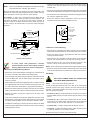
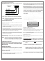
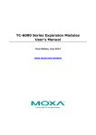
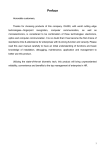
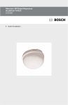
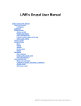
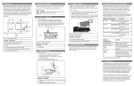
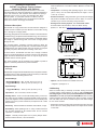
Installation Instructions
DS794Z Long Range Passive Infrared
Intrusion Detector with Self-test
• Trouble Output: A solid state open collector shorts to ground (-)
when the detector is in a trouble condition. Maximum current load
is 25 mA.
Trademark names are used throughout this document. In most cases,
these designations are claimed as trademarks or registered trademarks in
one or more countries by their respective owners. Rather than placing a
trademark symbol in every occurrence of a trademark name, Bosch
Security Systems, Inc. (hereinafter referred to as Bosch) uses the
names only in an editorial fashion and to the benefit of the trademark
owner with no intention of infringing the trademark.
• Temperature: The storage and operating range is -20° to +120°F
(-29° to +49°C). For UL Listed Requirements, the range is +32° to
+120°F (0° to +49°C).
1.0 General Description
The DS794Z is a high performance intrusion detector designed to
provide an alarm condition upon the detection of an intruder moving
into or through its coverage pattern.
Technology designed into the DS794Z is based on the transmission
of infrared energy; all objects transmit infrared energy. The warmer an
object is, the more infrared energy transmitted. The DS794Z detects
the change in infrared energy that occurs when a target passes
through its view.
• Sonalert Connector: Using a Sonalert type sounder (low voltage)
will provide an audible tone when the unit is in alarm. A sounder is
intended only as an aid for walk testing during installation.
• Reading Bosch Security Systems, Inc. Product Date Codes
For Product Date Code information, refer to the Bosch Security
Systems, Inc. Web site at: http://www.boschsecurity.com/datecodes/
CIRCUIT BOARD RETAINER TAB (2)
REPLACEABLE
OPTICAL MODULE
COVER TAMPER SWITCH
PERMANENT
RELFECTING MIRROR
TAMPER RELAY
TO REPLACE OPTICAL MODULE,
LIFT THIS EDGE UP
The coverage pattern, consisting of sensor fingers (to detect the
target) is arranged in a side-by-side array. The total number of fingers
is determined by the optical module used. The fingers are grouped
by polarity into pairs, with each pair consisting of one zone.
WALK TEST/ALARM
LED INDICATOR
4
5
6
7
8
To detect motion, the DS794Z must first see a change in infrared
energy in one finger followed by a change of energy in the remaining
finger. Therefore, disturbances that occur in only one finger do not
constitute motion and are ignored.
TERMINAL
STRIP
SETUP SWITCH BANK
(UNDER MIRROR ASSEMBLY)
BACKGROUND NOISE
VOLTAGE CONNECTOR
SONALERT™ CONNECTOR
(UNDER MIRROR ASSEMBLY)
Front view with cover off
SURFACE WIRE
ENTRANCE
The “catch sensitivity” may be changed by the installer to provide a
degree of sensitivity determined by each installation.
BRACKET WIRE ENTRANCE
SURFACE MOUNT
HOLES (4)
REAR WIRE
ENTRANCE
CORNER MOUNT
HOLES (4)
2.0 Specifications
REAR WIRE
ENTRANCE
• Coverage:
The DS794Z is shipped with the OA80 80 foot (24.4 m) Mirror installed.
If a 200 foot (61 m) range is desired, it will be necessary to install the
OA200 Mirror that is sent along with the unit.
TAMPER SCREW
HOLE
Base
Standard Range:
Broad (OA80 Mirror): 80 ft. by 50 ft. (24.4 m by 15.3 m)
Long (OA200 Mirror): 200 ft. by 10 ft. (61.0 m by 3.1 m)
COVER TABS (4)
TEST/SOUNDER
CORD SLOT
• Options: OA120-2* Mirror and TC6000 Test Cord.
* Shipped in packages of 2.
Optional Range:
Long (OA120 Mirror): 120 ft. by 25 ft. (36.6 m by 7.6 m)
• Input Power: 6.0 to 15.0 VDC; 18 mA at 12 VDC.
• Standby Power: There is no internal standby battery. Connect to
DC power sources capable of supplying standby power if primary
power fails. Eighteen mA-H required for each hour of standby time
needed. Four hours (72 mA-H minimum) are required for UL Listed
Requirements.
• Sensitivity: Field selectable for Standard, Intermediate, or High.
• Alarm Relay: Silent operating Form “C” relay. Contacts rated 125
mA, 28 VDC maximum for DC resistive loads. Do not use with
capacitive or inductive loads.
• Tamper: Normally Closed (with cover in place) tamper switch.
Contacts rated at 28 VDC, 125 mA maximum.
3.0 Mounting
Select a location likely to intercept an intruder moving across the
coverage pattern (review patterns on page 4). The recommended
mounting height is 7.5 ft. (2.3 m) for the DS794Z with the OA80 or
OA120 Mirror, or 10 ft. (3.1 m) for the OA200 Mirror. Each mounting
surface should be solid and vibration free. When mounting, avoid hot
and cold drafts, heat sources, animals and pets and direct sunlight.
Do not mount outdoors.
• Remove the cover by inserting a thin screwdriver into each of the four
slots on the cover. Twist gently until the cover snaps free of the tabs
on the base.
3.1 Bracket Mounting
NOTE:
The use of the B334 Mounting Bracket (included) is strongly
recommended when installing this detector.
Because variations exist in the surfaces of most mounting walls, most
units are not mounted at perfect angles to the floor or walls. This may
cause the pattern to point away from the “ideal” direction.
For example: A shift of only 1 degree will cause a pattern shift of
1.7 ft. (0.52 m) at 100 ft. (30.5 m). Under worst case conditions, this
will cause the pattern to be aimed over the head of intruders at
maximum range, or into walls of narrow corridors. What may seem to
be poor range or catch performance, may be the result of improper
alignment.
• Thread the bracket wiring through the stud and along the wiring
channel in the detector’s base to the area of the circuit board’s
terminal strip.
• Return the circuit board to its base. Slide the back of the circuit board
under the tabs at the back of the base, then snap the front into place.
• Aim the detector in the desired general direction and tighten the hex
nut using the supplied hex wrench.
• Should the detector require realignment, loosen the hex nut,
reposition the detector, and then retighten the nut.
WIRE ENTRANCE
STUD HOLE FOR
CEILING MOUNTED
BRACKET
B334 COVER
NOTCH
THREADED STUD
STUD HOLE (HIDDEN)
FOR WALL MOUNTED
BRACKET
B334 BODY
MOUNTING
HOLES (4)
DS794Z BASE
Lock Washer
B334 Bracket
3.2 Surface or Corner Mounting
WASHER EARS OUT
NOTCHED SIDE DOWN
CURVED WASHER
HEX NUT
• Remove the circuit board from its base. Press the two circuit board
retainer tabs outward and lift the circuit board away from the base.
• Select and break away the appropriate thin-wall wire entrance
covering the detector base.
• Using the base as a template, mark the location of the mounting
holes on the mounting surface. Pre-start the mounting screws.
Bracket to Base Assembly
To insure proper catch performance, a bracket
mounted detector permits the flexibility needed to
properly adjust the direction of the coverage pattern.
• Route the wiring to the rear of the base and through the wire
entrance. Firmly mount the base to the mounting surface.
NOTE: Be sure all wiring is unpowered (de-energized) before routing.
If Mounting to the B334 Mounting Bracket:
• Return the circuit board to its base. Slide the back of the circuit board
under the tabs at the back of the base, then snap the front into place.
• Remove the cover of the bracket by inserting a thin screwdriver into
the notch on the side of the bracket and twisting gently.
4.0 Wiring
• Insert the alarm and power wiring through the center hole from the
rear of the B334 base. (Do not insert wiring if the bracket is to be
surface mounted).
• Mount the B334 to a standard single-gang switch or outlet box using
the supplied Bevel Head screws. (If surface mounting the unit, use
the wall screw/anchor assemblies or appropriate alternatives).
• Remove the circuit board from its base. Press the two circuit board
retainer tabs outward and lift the circuit board away from the base.
• Remove the sticker covering the entrance from the back of the
detector base.
• Insert the threaded stud through the appropriate stud hole in the
B334 bracket. Use the bottom hole for wall mounting or the front hole
for ceiling mounting. Make sure the hex head is seated in place.
• Complete the assembly by securing the detector base to the B334
bracket using the supplied curved washer and hex nut (see drawing).
• Hand tighten the hex nut.
ONLY APPLY POWER AFTER ALL CONNECTIONS
HAVE BEEN MADE AND INSPECTED.
NOTE:
Do not coil excess wiring inside unit.
Locate the two-piece terminal strip on the side of the circuit board
assembly. Remove the wiring connector from the terminal strip by
inserting a screwdriver between the wiring connector and terminal
strip, and gently prying apart.
• Terminals 1 (-) & 2 (+): Power limits are 6 to 15 VDC. Use no smaller
than #22 AWG (0.8 mm) wire pair between the unit and the power
source.
• Terminals 3, 4, & 5: Alarm relay contacts rated 125 mA, 28 VDC
maximum for DC resistive loads. Use terminals 4 & 5 for Normally
Closed circuits. Do not use with capacitive or inductive loads.
• Terminals 6 & 7: Tamper contacts rated at 28 VDC, 125 mA.
• Terminal 8: Trouble. Solid State Trouble output. Shorts to ground
(-) when the detector is in a Trouble condition.
Re-install the wiring connector to the terminal strip.
Page 2
© 2011 Bosch Security Systems, Inc.
DS794Z Installation Instructions
5.0 Configuration Switch Settings
The supervision features function as follows:
The DS794Z has several features that are controlled using the
configuration switches.
• PIR: The operation of the PIR is electronically checked approximately
every 12 hours. If the PIR fails, the Alarm/Test LED will flash 4 times
and the Trouble Output will activate.
CONFIGURATION
SWITCHES
OFF
ON
2 ON and 3 ON = Standard Sensitivity
2 OFF and 3 ON = Intermediate Sensitivity
2 ON and 3 OFF = High Sensitivity
• Motion Monitor Supervision: This feature verifies that the detector
has a clear view of the detection area. When selected using switches
S4 and S5, a supervision timer is activated. A trouble condition will
be indicated if the detector has not alarmed at least once during the
selected time period (this feature can be disabled by placing both
switches in the Off position). The time period selected should be
long enough to allow adequate time for holiday weekends.
4 ON and 5 OFF = 4 Day Motion Monitor
4 OFF and 5 ON = 30 Day Motion Monitor
4 OFF and 5 OFF = Motion Monitor Off
Refer to Section 5.0 (Configuration Switch Settings) for proper
switch settings.
1
2
3
4
5
1 ON = LED ON
1 OFF = LED OFF
5.1 LED Operation (S1)
• ON:
Allows the Alarm/Test LED to operate when activated by
motion.
• OFF: The LED will not operate on alarm activation, but will indicate
a supervision trouble condition.
If the time period selected has elapsed from the last alarm, the LED
will flash 2 times and the Trouble Output will activate.
It is recommended that the 30 day timer be selected. This verifies
that the unit is operational and avoids nuisance trouble conditions
caused by holidays, vacations, etc.
5.2 Sensitivity Mode (S2 and S3)
Supervision Display Chart
Sensitivity modes depend on the type of coverage desired and the
installation environment.
LED
CAUSE
ON
Flashing 2
Flashing 4
Unit Alarm
Motion Monitor Timeout
PIR Self-test Failure
• Standard Sensitivity: The recommended setting for the DS794Z
with the 80 ft. (24.4 m) Mirror installed. Tolerates environment
extremes on this setting. Not recommended for the 120 ft. (36.6 m)
and 200 ft. (61 m) coverages.
7.0 Setup and Walk Testing
• Intermediate Sensitivity: The recommended setting for the 120 ft.
and 200 ft. (36.6 m and 61 m) coverages or for locations where an
intruder is expected to cover only a small portion of the protected
area. Tolerates normal environments on this setting.
If a different optical module is to be used:
• High Sensitivity: The setting for fast response to intruder signals.
For use in quiet environments where thermal and illumination
transients are not anticipated.
NOTE: Excessive handling of the front mirrored surfaces may lead
to performance degradation.
If both switches are in the Off position, the unit will default to the
Intermediate setting.
NOTE:
Although the sensitivity modes provide different degrees of
tolerance to environmentally caused alarms, the installer
should assure peak background noise voltage readings do
not exceed ±0.15 VDC. (See Section 8.0 Final Tests).
5.3 Motion Monitor (S4 and S5)
Set switches S4 and S5 for the desired Motion Monitor time (see
Supervision Features). The detector is shipped with the Motion
Monitor feature Off.
6.0 Supervision Features
The DS794Z performs several supervision features that, combined
with the advanced motion detection capabilities of the detector,
provide an extremely high level of security. A supervision trouble
condition is indicated at the detector by the Alarm/Test LED (see the
Supervision Display Chart).
• The LED indicates the cause of the supervision trouble once per
second using coded pulses. The supervision trouble signal activates
the Trouble Output available on terminal 8.
DS794Z Installation Instructions
• Slide the current module free from its housing. Install the new optical
module onto the housing. Make sure it snaps into place.
• Replace the front cover.
NOTE: All testing must be performed with the front cover in place.
• Apply power to the unit.
• Wait at least two minutes, after applying power, to start walk tests.
For best results, wait at least 1 minute between walk tests to allow
the processing to adjust to the background.
NOTE: Walk testing should be done across the coverage pattern as
shown.
• The edge of the coverage pattern is determined when the Alarm/Test
LED indicator (and optional Sonalert, if installed) first turns on.
NOTE: The use of a Sonalert type device (sounder) will provide an
audible tone during the time the unit is in alarm. Of the three
available connector pins, the center pin is positive (+) with
respect to either outside pin (outside pins are common (-)).
Walk test the unit from all directions to determine the boundaries.
• After completion of the walk tests, remove the Sonalert (if installed).
© 2011 Bosch Security Systems, Inc.
Page 3
8.0 Final Tests
10.0 Coverage Patterns
NOTE: Meter readings are very important in determining back ground
disturbance levels and catch margin sensitivity.
TOP VIEW
0 METERS
24
30
• Connect a 20,000 ohm/volt (or greater) DC VOM to the Noise Voltage
connector pins as shown. Set meter scale for about 3 VDC. Route
meter wiring through the slot in the base. (Use of the TC6000 is
recommended, but is not essential for meter use.)
Mirror to Pattern
Reference
A
20
K
F
B
10
I
F
A
0
• The base reference level for reading background noise or target
voltages is approximately 2.0 VDC. Installations in quiet
environments, therefore, will result in a steady meter reading
between 1.9 and 2.1 VDC.
G
K
C
I
J
H
G
J
10
H
D
B
C
D
E
20
E
30
Voltage changes greater than 0.75 VDC from the reference level are
desirable for good catch performance. If changes are less than
±0.75 VDC, the device may fail to respond at this distance if the
temperature difference between the intruder and the background is
very small.
0 FEET
80
SIDE VIEW
0 METERS
24
OA80
10
K
I, J
0
A-E
F-H
0 FEET
80
OA80 Mirror Coverage
• Turn on all heating and cooling sources that would normally be in
operation during times of protection. Stand away from the unit and
outside the coverage pattern, then monitor the background noise
for at least three minutes.
TOP VIEW
0 METERS
36
Mirror to Pattern
Reference
20
DS794Z readings should not deviate from the reference level more
than ±0.15 VDC. For readings outside these limits; eliminate the
cause, re-point the unit slightly, or mask off the affected zones.
10
A
D
I
0
G
I
E
H
B
F
D
A
C
10
G
E
H
F
20
0 FEET
9.0 Other Information
120
B
SIDE VIEW
0 METERS
9.1 LED Indicator Operation
C
36
10
7.5
I
0
• If viewing the operation of the Alarm/Test LED indicator is not
desired after setup and walk tests are completed, place configuration
switch S1 in the Off position.
G,H
A-C
D-F
OA120
120
0 FEET
OA120 Mirror Coverage
9.2 Sealing the Wire Entrance
TOP VIEW
• The foam plug that is provided with the unit is for sealing the wire
entrance from drafts and insects.
0 METERS
61
0 FEET
200
5
0
5
9.3 Maintenance
SIDE VIEW
0 METERS
• At least once a year, the range and coverage should be checked
according to Sections 7.0 and 8.0 (Walk Testing and Final Tests).
• To ensure continued daily operation, the end user should be
instructed to daily walk through the far end of the coverage pattern.
This assures an alarm output prior to arming the system.
61
10
0
0 FEET
200
OA200 Mirror Coverage
Mirror to Pattern
Reference
9.4 Mirror Module Information
D
• Should the mirror surfaces become soiled or dirty, clean using a soft
clean cloth and any commonly available mild window cleaner.
E
C
B
9.5 Masking
• Refer to the mirror module and pattern drawings for masking
information.
A
OA200
• Before attempting any masking, be sure the chosen mirror surface
is the correct one. When attempting to remove any masking, many
adhesives will either destroy the mirror’s surface or leave enough
residue behind to reduce coverage performance.
• Shaded areas of the mirror drawings do not affect the pattern and,
therefore, are not maskable.
© 2011 Bosch Security Systems, Inc.
130 Perinton Parkway, Fairport, New York 14450
www.boschsecurity.com
3/11
DS794Z Installation Instructions
P/N: F01U068930-06 Page 4