1
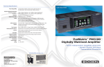
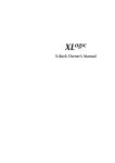
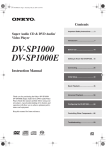
User’s guide
Models PM-3000 & PM-3180
User’s Guide
Part No. 54-5003-02
9707
© 1996 Bogen Communications, Inc.
50 Spring St., Ramsey, NJ 07446
Warning: Changes or modifications
to this unit not expressly approved
by the party responsible for compliance could void the user’s authority
to operate the equipment..
All rights are reserved. No part of this
document may be photocopied, reproduced, or translated to another language
without the prior written consent of
Bogen Communications Inc.
Note: This equipment has been
tested and found to comply with the
limits for a Class A digital device,
pursuant to Part 15 of the FCC
Rules. These limits are designed to
provide reasonable protection
against harmful interference when
the equipment is operated in a commercial environment. This equipment generates, uses, and can radiate radio frequency energy and, if
not installed and used in accordance
with the instruction manual, may
cause harmful interference to radio
communications. Operation of this
equipment in a residential area is
likely to cause harmful interference
in which case the user will be
required to correct the interference
at his own expense.
Notice: The information contained in
this document is subject to change without notice and should not be construed
as a commitment by Bogen Communication, Inc.
Bogen Communications Inc. assumes
no responsibility for any errors that
may appear in this document nor
does it make expressed or implied
warranty of any kind with regard to
this material, including, but not limited to, the implied warranties of merchantability and fitness for a particular purpose.
Bogen Communications Inc. shall not be
liable for incidental or consequential
damages in connection with, or arising
out of the furnishing, performance, or
use of this document and the equipment
which is describes
This Class A digital apparatus meets
all requirements of the Canadian
Interference-Causing Equipment
Regulations
Complete product warranty information
is provided on a separate product registration card.
Cet appareil numérique de la classe
A respecte toutes les exigences du
Règlement sur le matériel brouilleur
du Canada.
WARNING
The Warning label calls attention to a
procedure, practice, or the like, which, if
not correctly performed or adhered to,
could result in damage to the unit or
personal injury. Do not proceed
beyond a warning label until the indicated conditions are fully understood and
met.
Publication No. 54-5003-02
July 1997
Printed in Korea
ii
Models PM-3000 & PM-3180
User’s Guide
Owner’s Information
Model Number
Serial Number_________________________
Date of Purchase______________________
Place of Purchase_____________________
Address______________________________
____________________________________
iii
Contents
Unpacking . . . . . . . . . . . . . . . . . . . . . . . . . . . . . . . . . . . . . .1
Packing List . . . . . . . . . . . . . . . . . . . . . . . . . . . . . . . . . . . .1
Accessories . . . . . . . . . . . . . . . . . . . . . . . . . . . . . . . . . . . .1
Conventions . . . . . . . . . . . . . . . . . . . . . . . . . . . . . . . . . . . .1
Introduction . . . . . . . . . . . . . . . . . . . . . . . . . . . . . . . . . . . . .2
Description . . . . . . . . . . . . . . . . . . . . . . . . . . . . . . . . . . . . .2
Features . . . . . . . . . . . . . . . . . . . . . . . . . . . . . . . . . . . . . . .3
Quick Start . . . . . . . . . . . . . . . . . . . . . . . . . . . . . . . . . . . . . .4
Install Control Panel . . . . . . . . . . . . . . . . . . . . . . . . . . . . . .4
Basic Wiring . . . . . . . . . . . . . . . . . . . . . . . . . . . . . . . . . . . .5
Factory Programmed Configuration . . . . . . . . . . . . . . . . . . .6
Basic Operation . . . . . . . . . . . . . . . . . . . . . . . . . . . . . . . . .7
Aux Input Trim Adjustment . . . . . . . . . . . . . . . . . . . . . . . . .10
Important Operational Notes . . . . . . . . . . . . . . . . . . . . . . .10
Rear Panel Model PM-3000 . . . . . . . . . . . . . . . . . . . . . . . .11
Rear Panel Model PM-3180 . . . . . . . . . . . . . . . . . . . . . . . .12
Front Panel . . . . . . . . . . . . . . . . . . . . . . . . . . . . . . . . . . . .13
Infrared Remote Controller . . . . . . . . . . . . . . . . . . . . . . . .14
Wiring Information . . . . . . . . . . . . . . . . . . . . . . . . . . . . . . .15
Outputs for Model PM-3000 . . . . . . . . . . . . . . . . . . . . . . . .15
Outputs for Model PM-3180 . . . . . . . . . . . . . . . . . . . . . . . .16
Aux Inputs . . . . . . . . . . . . . . . . . . . . . . . . . . . . . . . . . . . . .17
Aux Input Trim Controls . . . . . . . . . . . . . . . . . . . . . . . . . . .17
Audio Process Link Wiring (PM-3180 Only) . . . . . . . . . . . .17
Mic Inputs . . . . . . . . . . . . . . . . . . . . . . . . . . . . . . . . . . . . .18
User Operation . . . . . . . . . . . . . . . . . . . . . . . . . . . . . . . . .19
The ProMatrix Control Panel . . . . . . . . . . . . . . . . . . . . . . .19
Programming . . . . . . . . . . . . . . . . . . . . . . . . . . . . . . . . . . .22
Enter Program Mode . . . . . . . . . . . . . . . . . . . . . . . . . . . . .22
Programming Menu . . . . . . . . . . . . . . . . . . . . . . . . . . . . . .23
Assignment . . . . . . . . . . . . . . . . . . . . . . . . . . . . . . . . . . . .24
Mic Set Up . . . . . . . . . . . . . . . . . . . . . . . . . . . . . . . . . . . .26
Presets . . . . . . . . . . . . . . . . . . . . . . . . . . . . . . . . . . . . . . .28
Volume Limit . . . . . . . . . . . . . . . . . . . . . . . . . . . . . . . . . . .30
Inhibit . . . . . . . . . . . . . . . . . . . . . . . . . . . . . . . . . . . . . . . .32
Aux Mute . . . . . . . . . . . . . . . . . . . . . . . . . . . . . . . . . . . . .33
Amplifier Link (PM-3180 Only) . . . . . . . . . . . . . . . . . . . . . .34
Password . . . . . . . . . . . . . . . . . . . . . . . . . . . . . . . . . . . . .35
Labels . . . . . . . . . . . . . . . . . . . . . . . . . . . . . . . . . . . . . . . .36
Factory Defaults . . . . . . . . . . . . . . . . . . . . . . . . . . . . . . . .37
Testing & Troubleshooting . . . . . . . . . . . . . . . . . . . . . . . .38
Testing . . . . . . . . . . . . . . . . . . . . . . . . . . . . . . . . . . . . . . .38
Troubleshooting . . . . . . . . . . . . . . . . . . . . . . . . . . . . . . . . .39
Getting Help . . . . . . . . . . . . . . . . . . . . . . . . . . . . . . . . . . . .41
Specifications . . . . . . . . . . . . . . . . . . . . . . . . . . . . . . . . . .42
iv
Unpacking
Packing List
The ProMatrix carton contains the following components:
1 - ProMatrix unit
1 - Removable Control Panel*
1 - Wireless Infrared Remote Controller
2 - AAA Batteries
1 - 25-foot Control Panel Cable
1 - AC Power Cord
2 - Wall Anchors
1 - User Manual
1 - Product Registration Card
*The control panel must be connected to the amplifier chassis prior to operation. See page 4 to install control panel.
Accessories
A front panel mount kit and rack mount kit are available for this product.
• The front panel mounting kit lets you customize installation by locating the
control panel remotely from the amplifier chassis (up to 250 feet when inwall wiring is used). Front Panel Mounting Kit Part No.: RMPWMK3
• The rack kit permits installation of the amplifier chassis in standard equipment racks. Rack Panel Kit Part No.: RPK79
Conventions
This users guide covers the ProMatrix amplifier, model PM-3180 and the
ProMatrix Preamplifier, model PM-3000. Each of these units incorporates
three channels — amplifier channels in PM-3180 and preamplifier channels
in PM-3000. This manual refers to the three channels as amp/channels to
indicate that the instruction refers to either the three amplifier channels or
three preamplifier channels.
1
Introduction
Description
The ProMatrix products are designed for sound reinforcement/distribution in
multi-room applications. The PM-3180 consists of three independent amplifiers, rated at 20, 60 and 100 watts. The PM-3000 is a three channel preamplifier unit designed to offer the flexibility for applications with power
requirements that exceed the limits of the PM-3180. Both units have a programmable interface that lets you selectively assign priority levels to inputs
and custom configure features. As inputs become active or inactive they
are automatically switched onto or off of the channel.
Four Aux inputs and two Mic inputs lets you connect to a wide variety of
program sources. One of the Mic inputs can be set to accept input from a
telephone paging interface. The PM-3180 has outputs for 4- and 8-ohm
loads as well as 25V and 70V distributed systems, and includes provisions
to connect external signal processing equipment. The PM-3000 provides
both balanced and unbalanced line level output for each channel.
Here is an application example for a typical restaurant/bar establishment using the PM-3180 amplifier: The 20-watt amp channel plays to the
entrance area/waiting room, the 60-watt amp channel to the dining area,
and the 100-watt amp channel to the bar/lounge. The area served by each
amp channel hears program material according to the priority level for the
inputs assigned to the amp channel. This example is illustrated below:
Amplifier Channel
Area Served
PM-3180
Input
Aux A
Aux B
Aux C
Aux D
Mic A
Mic B
Audio
Source
Juke Box
CD Player
Radio
TV Feed
Emerg. Mic
Page Mic
Amp 1 (100W)
Lounge
3
4
5
6
1
2
Amp 2 (60W)
Dining Area
Amp 3 (20W)
Waiting Room
Assigned Input Priorities
—
2
3
—
1
—
—
3
4
—
1
2
1 = Highest Priority, 6 = Lowest Priority, — = Input not assigned to amp.
The lounge audio sources and microphones are prioritized as shown, with
the Mics having the highest priorities and the music source with descending
priorities. The dining area has completely different audio needs where certain audio sources (like the paging mic and juke box) are inhibited from use
in that area while the CD and radio are permitted to play. Likewise for the
waiting area where the inputs are assigned and prioritized for that area.
2
Introduction
Features
The ProMatrix units have the following features:
• 2 Lo-Z balanced Mic inputs (Mic A is female XLR, Mic B is screw terminals). Mic B can be configured as a 600-Ohm transformer balanced
input for telephone paging applications.
• Automatic level control for Mic inputs.
• Choice of microphone precedence activation (VOX, Normally Open,
Normally Closed).
• Phantom power for use with condenser microphones.
• 4 Aux inputs (RCA unbalanced).
• Aux Input trim controls to adjust for differing audio source input levels.
• Automatic switching of inputs based on input activity.
• Flexible priority assignments for each input on each amplifier channel
• Fade-in of audio source after Mic page or when switching to a lower
priority input.
• Adjustable paging over music level.
• Wireless infrared remote control unit with the same functions as the
control panel.
• Front-mounted, removable control panel with soft-touch buttons to:
— select a channel
— provide manual override selection of input source
— control volume, treble and bass.
— program unit functions
• Preset power-up volume level of each input for each channel.
• Password protected programming mode.
• Preset bass and treble response of each input on each channel (the
same input can have different EQ settings on different channels).
• Preset maximum volume level the user can achieve.
• Lock out or inhibit volume bass and treble controls for each channel.
• Non-volatile memory to retain user control settings.
• Change the access code.
• Create custom display names for input sources.
• Front panel mounted LED output level meters for each amp channel.
• Reset to factory default values.
The PM-3000 includes:
• Balanced & unbalanced Line Level outputs for each channel
• Ground lift switch
The PM-3180 has these additional features
• Independent 20, 60 & 100 watt amplifiers in one package.
• 4, 8Ω, 25V & 70V outputs on each amp.
• Thermostatically-controlled cooling fan.
• Audio process links permit installation of signal processing equipment.
3
Quick Start
This Quick Start section is intended to assist you in getting the ProMatrix
unit up and running quickly so that you can become familiar with it.
Important: Do not place any objects directly on top of the unit.
Leave at least 2 inches of space above the unit to assure proper ventilation. When locating the PM-3180, be sure to leave at
least 2 inches of space on the right side of the unit to allow for
fan exhaust.
Install Control Panel
The unit is shipped with the control panel disassembled from the chassis.
You have the option of attaching the control panel to the front panel or
mounting it in a convenient location and connecting it to the unit using the
25-foot telephone cable included. For longer cable runs, use accessory
RMPWMK3 for secure and attractive mounting of the front panel up to 250
feet from the main unit.
Warning: Use only the telephone cable supplied. Use of any
other cable may damage the unit.
To attach the control panel to the chassis, position the panel as shown. Line up
the tabs on the control panel with the
slots on the chassis. Push in on the
grooved areas on each side of the plastic panel and push the control panel onto
the chassis to engage the locking tabs.
Tabs
To mount the control panel in a
remote location:
1. Install two wall anchors 4-inches apart and level in the desired
location. The screws should protrude 1/2”.
Slots
Fan Outlet
(PM-3180 only)
Do Not Block
2. BE SURE THAT POWER IS OFF WHEN YOU INSTALL OR REMOVE
THE CONTROL PANEL. Plug one end of the 25-foot remote cable into
the jack on the bottom right corner of the control panel. Plug the other
end into the jack labeled REMOTE on the rear panel of the ProMatrix
unit.
3. Place the control panel keyhole slots over the protruding screw heads
and pull down slightly to secure the panel.
Note: The panel must be oriented vertically to ensure proper
cooling of the internal electronic components.
4
Quick Start
Basic Wiring
1. Temporarily set the AUX INPUT TRIM
controls on the rear panel to their full
counterclockwise position. Trims will
be adjusted later.
2. Be sure that the voltage select switch
is set correctly. Connect the power
cord to the AC LINE INPUT
3. Connect outputs.
For the PM-3000, connect the correct
style output (balanced or unbalanced)
to the input of the external amp or
other signal processing equipment.
Refer to page 15 for wiring balanced
or unbalanced outputs.
For the PM-3180, connect loads
between COM and the desired
output tap (8Ω, 25V or 70V). If
connecting a 4-ohm load, refer to
the Wiring Information section on
page 16 for information on the
4Ω link.
4. Connect unbalanced music input
sources. The lines from the sources
to the amplifier should be terminated
with RCA-type plugs.
5. Connect balanced, low-impedance
microphones. For the 3-pin Mic A
connector, pin 1 is ground (shield).
+
6. Plug the ProMatrix into a properly
grounded wall outlet.
5
Quick Start
Factory Programmed Configuration
When the ProMatrix unit is first powered up, the factory default settings are
loaded.
The factory default priority table is listed below. If you want to change any
of these priority levels, you will have to use the ASSIGNMENT function in
the programming mode. See the Programming section of these instructions
(Page 22) to set priority levels.
Input
MIC A
MIC B
AUX A
AUX B
AUX C
AUX D
Priority Level
1
2
3
4
5
6
(1 = highest, 6 = lowest)
The microphone input settings are listed below:
Microphone
MIC 1
MIC 2
Feature
Precedence
ALC
Phantom
Precedence
ALC
MIC/TEL
Phantom
Default
VOX
ON
ON
VOX
ON
MIC
ON
Options
N.O., N.C., VOX
ON, OFF
OFF, ON
N.O., N.C., VOX
ON, OFF
MIC, TEL
OFF, ON
See the Programming section of these instructions (starts on page 22) if
you want to configure the microphones for other than the default values.
6
Quick Start
Basic Operation
This section will show you how to:
•
•
•
•
•
•
•
Apply power to the unit
Understand the Control Panel (See page 12 for full description)
Select which channel the control panel affects
Change volume
Change Bass and Treble response
Manually select an input or allow priority-based switching
Adjust Aux Input Trim Controls
To Apply Power to the Unit
Important Note: For PM-3000, make sure any power amplifiers connected to the unit are off when the unit is first plugged in.
Connect the AC supply cord to the unit and plug it into an outlet (the unit
will turn on and display the software part number for 2 seconds and then
the unit will shut down). To apply power, press the button labeled POWER
on the control panel or on the wireless infrared remote controller.
Understanding the Control Panel
The ProMatrix unit consists of 3
channels but only one control
panel. Therefore, you must select
the channel that the panel will
effect. Once the unit is powered,
a number of indicators will light
and the alphanumeric panel will
display status information.
AUXA
The illuminated AMP 1 indicator
means that it is the “current”
amp/channel — the one that the front panel controls will now effect. AUX A
is the current active input and VOL is the current active control function.
AUTO indicates that the inputs will auto switch. The pointer LED segment
(between the large arrow keys) shows the approximate volume level.
To Select an Amp or Preamplifier Channel
To make another amp/channel current (under effect by the control panel),
press the desired button (AMP 2, AMP 3); its indicator will illuminate.
Once selected, the user can adjust the VOL, BASS or TREB control for the
selected amp/channel.
7
Quick Start
To Control Volume
Note: Changing any of the volume, bass or treble levels will
effect all inputs associated with that amp/channel channel.
Turning up the volume for the current amp/channel will cause
other inputs assigned to that amp/channel to play louder when
they become active. Likewise for bass and treble.
Be sure VOL is the current control (this is the
normal default function). If BASS or TREB are
lit, press the VOL button. Its indicator will light
brightly and the volume level is displayed on the
LED pointer.
Press the arrow buttons on either side of the
pointer (left to decrease, right to increase).
The display shows A1 (the active amp/channel), VOL, and a 2-digit volume level number
(00-25). The number (and pointer) changes
in response to the arrow buttons.
A1/VOL-10
After 5 seconds of no adjustment, the control
panel display will again show the current
input (VOL remains the current control and can
be adjusted at any time simply by pressing an
arrow key).
To Control Bass or Treble.
Select the desired function by pressing the
BASS or TREB button – its indicator lights.
The display shows BASS (or TREB), the current
active amp/channel (A1) and a 1-digit level
number (-7 to+7). The pointer shows the
approximate level.
Press the arrow buttons on either side of the
pointer. The number on the display changes
in response to the arrow buttons.
After 5 seconds of no adjustment, the amplifier
display will again show the current input and
VOL will again become the current function.
8
A1/bass 0
Quick Start
To Select a Specific Input
The ProMatrix unit is normally set to monitor input activity and, based on the
default or installer-created priority table, automatically switches the proper
input for each amp/channel. You can override the priority switching feature
of any amp/channel to select a specific input to be on continuously.
1. Press the AUTO button. Its indicator
LED will flash. and the alphanumeric
display will show SEL INPUT.
2. Press the desired input selector button (MIC A/B, AUX A/B/C/D). The
selected input will appear on the display and its indicator will flash (50%
on/50% off) in sync with the AUTO
indicator.
Note: If a different amp/channel is selected, the AUTO LED will
flicker (90% on/10% off) to indicate that one or more of the
other amp/channels is under manual control.
To identify which amplifier is under manual control
Press each AMP button until the AUTO indicator and input indicator (AUX
A, B, etc.) flash together.
To Return to Auto Switching
Find the amp/channel that is under manual control.
Press the AUTO button once. The current input (based on priority) will
appear on the display. Its indicator will light steady as will the AUTO indicator (unless another channel is in manual mode, in which case the indicator
will flicker). This sets only the current amp/channel into the auto-switch
mode. Any other amp/channels that have manually selected inputs will
need to be returned to auto-switch mode using the same procedure
described above.
Note: The amp/channel must be in AUTO mode before another
manual input can be selected.
9
Quick Start
Aux Input Trim Adjustment
By adjusting the Trim controls as follows, inputs with different signal levels
are set approximately equal within the ProMatrix unit.
Important: You must properly set the Aux Input Trim Controls.
Improperly adjusted trims can result in high distortion levels,
poor volume balance between different inputs or false triggering
of inputs.
To adjust trims, follow the procedure below:
1. Make sure the various input sources are attached and operating at their
normal output levels.
2. Select Amp 3 as the current amp/channel.
3. Press the AUTO button and manually select one of the Aux inputs (Start
with Aux A).
4. Raise the volume of Amp 3/Aux A to 25 (this can be done without a
load, if desired).
5. Rotate the Aux A Input Trim control while watching the Amp 3 output
level meter. Adjust the trim control so that the red LED is briefly flashing only on loud music peaks.
6. Repeat steps 3, 4, and 5 for the other Aux inputs. Since the inputs are
common to all three amplifier channels, the trims only need be set for
one of the amp channels.
7. For PM-3000, you must also set each of the external amplifiers volume
controls for the maximum sound level desired while the PM-3000 volume is set to 25.
Important Operational Notes
• Phantom power is turned on from the factory. To turn it off, see the
Programming Section, starting on page 22.
• When a microphone becomes active (through Vox or contact closure),
the current Aux input will be muted to a preset level. No Aux input
switching is allowed when the Aux mute is active.
10
Rear Panel Model PM-3000
6
7
1
2
3
4
5
8
9
10
11
1. MIC A — Female XLR-type connector for balanced,
LO-Z microphone input. Pin 1 is Gnd.
2. MIC B/TEL B — Screw terminal Input for Lo-Z balanced microphone.
Software configurable as a 600Ω transformer coupled paging interface.
3. MIC PREC — Microphone precedence terminals for contact closure
activation.
4. AUX INPUT — Unbalanced input jacks (RCA type) for program
sources.
5. AUX INPUT TRIM — Variable attenuators for adjusting input source
levels.
6. BALANCED OUTPUTS — Balanced Preamp output screw terminals for
each channel.
7. UNBALANCED OUTPUTS — Unbalanced preamp output RCA jacks.
8. GROUND LIFT — Disconnects output grounds from chassis ground.
9. REMOTE — Jack for use when mounting amplifier front control panel in
a remote location.
10. VOLTAGE SELECT — Voltage Selector switch.
11. AC LINE INPUT — Power cord socket.
12. Fuse — 120VAC/0.5A, 240VAC/.25A
11
12
Rear Panel Model PM-3180
8
1
2
3
4
5
6
7
9
10
1. MIC A — XLR-type connector for balanced, LO-Z microphone input.
Pin 1 is Gnd.
2. MIC B/TEL B — Input for Lo-Z balanced microphone. Software configurable as a 600Ω transformer coupled paging interface.
3. MIC PREC — Microphone precedence terminals for contact closure
activation.
4. AUX INPUT — Unbalanced input jacks (RCA type) for program
sources.
5. AUX INPUT TRIM — Variable attenuators for adjusting input source levels.
6. AUDIO PROCESS LINKS — Permits the connection of external signal
processing equipment.
7. REMOTE — Jack for use when mounting amplifier front control panel in
a remote location.
8. Amplifier output screw terminals.
9. VOLTAGE SELECT — Voltage selector switch.
10. AC LINE INPUT — Power cord socket.
11. Fuse — 120VAC/4A, 240VAC/2A.
12
11
Front Panel
1
7
6
AUXA
9
2
10
3
8
4
5
1. Alphanumeric display area.
2. AUX A/B/C/D — Input selector buttons & indicators.
3. AUTO — Controls manual or automatic input selection.
4. POWER — Applies power to the ProMatrix unit.
5. AMP 1/2/3 — Amp/Preamp Channel Selector Buttons.
6. Level control Arrow buttons.
7. LED pointer area.
8. PROG, NEXT, BACK, ENT & EXIT — Programming buttons.
9. MIC A/MIC B — Microphone input selector buttons.
10. VOL/BASS/TREB — Function control selector buttons.
13
Infrared Remote Controller
The infrared remote controller provides all of the functions of the front panel.
Before using the controller, install two AAA-size batteries in the battery compartment of the controller. Be sure to observe correct polarity.
To use the controller, point the controller at the infrared receiver window on
the left side of the front panel of the ProMatrix chassis and press the
desired button.
1. POWER — Controls power to the
ProMatrix unit.
2. MIC A & MIC B — Manual microphone selector buttons.
1
3. AUTO — Toggles between auto
input selection and manual input
selection.
2
4. AUX A/B/C/D — Manual input
selector buttons.
5
A
B
3
4
6
5. AMP 1/2/3 — Amp/channel selector buttons
6. TREB/BASS/VOL — Function
selector buttons
7. Up/down Arrows — Used to adjust
level of TREB/BASS or VOL.
8. Programming buttons.
14
8
7
Wiring Information
Outputs For PM-3000 Preamplifier
Each preamplifier channel has its own balanced output terminals and unbalanced RCA output jacks on the rear panel to handle different amplifier and
signal processing inputs.
1
2
1. This figure shows wiring
from the PM-3000
Balanced Output to a
standard XLR-type of
balanced amplifier input.
3
Note 1
Note 1. In some instances, connecting the cable shield
to both the PM-3000 ground and the amplifier’s input
ground may cause ground loops. In that case, remove
the shield connections to the PM-3000.
2. This figure shows wiring
from PM-3000 Balanced
Output to an unbalanced
input. Note: this wiring
style into an unbalanced
input will result in 6dB
less maximum input signal. The unbalanced
connection shown in 3. is
preferred.
3. Wiring for PM-3000 into
unbalanced inputs.
Provides maximum signal level drive into unbalanced inputs.
15
Wiring Information
Outputs For PM-3180 Amplifier
Each amplifier channel has its own output terminal strip on the rear panel.
Each terminal strip can handle a different type of speaker load. All amps
can handle 70V & 25V distributed or 8-Ω or 4-Ω loads. The
70V, 25V and 8-Ω outputs are
transformer-coupled. The 4-Ω
output is directly connected to
the amplifier output. The 4-Ω
output provides a wider fre8-Ω Load
quency response with better
bass reproduction and lower
distortion.
To connect an 8-Ω, 25V or 70
load, attach one lead to the
COM terminal and the other to
the terminal corresponding to
the output desired. Ensure
that the shorting clip connects
COM and GND and that the
shorting clip for the LINK is
installed.
25V or 70V
Load
The transformer-coupled outputs (70V, 25V, 8-Ω) can be
made to float by disconnecting
the shorting clip between GND
and COM. This may be desirable in certain situations where
a balanced output is needed.
In general, it is best to keep the
shorting clip installed between
GND and COM.
To connect a 4-Ω load, first
remove the shorting clip
between the two screw terminals marked LINK. Connect
one lead of the 4-Ω load to the
4-Ω terminal and the other lead
to the GND terminal.
4-Ω Load
16
Wiring Information
AUX Inputs
Unbalanced input sources other than microphones are connected to the
AUX INPUT jacks. The output lead from the source must be terminated in
an RCA-type plug. The input signal range is 100mVrms to 3Vrms and is
adjusted using the AUX TRIM controls.
Unbalanced
audio source
(CD/Tape/Tuner/Etc.
Aux Input Trim Controls
See page 10 for adjustment procedure
Audio Process Link Wiring (PM-3180 Only)
Typical Audio Process Link wiring is illustrated below. See page 32 in the
Programming section to deactivate the internal connection between the preamp out and power amp in so that the external equipment can be inserted.
EQ In
EQ Out
17
Wiring Information
MIC Inputs
Mic A
2
1
Pin 1 is GND
Pin 2 (+)
Pin 3 (-)
3
If Mic A has a push-to-talk switch, use these terminals for the switch connection (see Mic Precedence
Setup in the Programming Section).
Mic B
Shield
Push-to-talk switch pair.
Normally open or normally
closed (see Mic Precedence
Setup in Programming
Section).
MBS-1000
Mic B/Tel
T
PBX Page Port
or Paging Adapter
R
*
X
*Switch closure available on some page ports.
Program the unit for correct switch precedence or use VOX precedence if
no switch closure is available.
18
User Operation
The ProMatrix Control Panel
The control panel is the interface between the user and the unit functions.
Since there are three channels (amp or preamp) and only one control panel,
the ProMatrix uses selector buttons, indicators and an alphanumeric display
to provide control of the overall functions. The information below will familiarize you with the operation of the control panel.
The control panel typically shows the following information:
• The currently active amp/channel — the one that is currently under control panel control — by means of an indicator lamp.
• The currently active input — shown on the alphanumeric display and
indicator lamp.
• Input selection status — either automatic or manual selection
• The currently active control — VOL, BASS or TREB — which can be
adjusted by pressing the arrow buttons.
If the arrow keys are not touched for 5 seconds, the unit defaults to the
VOL control; you have to first select BASS or TREB to use these controls.
When the ProMatrix is in User Mode, the user can perform the following
functions
•
•
•
•
Apply power
Select a channel
Adjust volume and tone for all inputs on the selected amp/channel
Manually select an input
To Apply Power to the ProMatrix Unit
To apply power, press the button labeled POWER on the control panel. or
on the wireless infrared remote controller.
To Select an Amp/Channel
In order to change the volume or tone for an amplifier channel, the
amp/channel must first be selected. To select, press the desired AMP button (AMP 1, AMP 2 or AMP 3). Its indicator will illuminate brightly. The current input for that amp will appear on the alphanumeric display panel.
Once an AMP is selected, the user can adjust the VOL, BASS or TREB
control to the selected AMP.
19
User Operation
To Control Volume, Bass or Treble
Note: Changing any of the volume, bass or treble levels will effect all
inputs associated with that amplifier channel. Turning up the volume
for the current amplifier will cause other inputs to play louder when
they become active. Likewise for bass and treble.
1. To control volume, bass, or treble you must first select the desired control (VOL, BASS, TREB so that its indicator LED lights. The LED pointer will light to indicate the approximate level setting.
2. Press the arrow buttons on either side of the pointer. The display will
show (assuming Amp 1 is the selected amplifier):
For Volume: A1/VOL-XX, where XX is a 2-digit number from 00 to 25, corresponding to the volume level.
For Treble: A1/TREB X, where X is a digit from -7 to +7, corresponding to
the amount of cut or boost.
For Bass: A1/BASS X, where X is a digit from -7 to +7, corresponding to
the amount of cut or boost.
3
After 5 seconds of no adjustment, the alphanumeric display will return
to the previous display and show only the current input.
Note: The volume and tone controls for a particular amplifier can be
programmed so that they do not respond to the control panel (or
infrared remote) buttons. If this programming has been performed, the
word INHIBITED will appear on the alphanumeric display when the controls
are pressed.
Note: The volume of the ProMatrix is affected by three constraints: 1)
the preset level, 2) volume changes made by the user and 3) the volume limits if set. The case may occur where the user raises the volume level to the limit set for the current input. If the input then
changes, the volume level and limit for the new input may allow further
increase of the volume. If the original input once again becomes
active, it will still be held at the limit for the second input. Now, if the
user lowers the volume of this input, the levels of all the other inputs
will change to reestablish the differences set by programming. In so
doing, all other non-active inputs may change by more than the
amount
20
User Operation
the current input was lowered by. This is because the levels set by the user are
temporary and the ProMatrix always strives to maintain volume differences set by
the preset programming. Typically, this will only occur when the inputs or limits are
set vastly different for the inputs assigned to an amp channel. The same applies to
the tone controls where the amp tries to maintain the EQ differences.
To Select a Specific Input
The amplifier monitors active inputs and, based on the default or installercreated priority table, automatically switches the proper input for each channel. You can override the priority switching feature to select a specific input.
1. Press the AUTO button. Its indicator LED will flash and SEL INPUT
appears on the display panel.
2. Press the desired input selector button (MIC A/B, AUX A/B/C/D). The
AUTO LED and selected input LED will flash to indicate that autoswitching is off for this channel.
Note: You must return to auto-switching before manually selecting
another input.
Note: If one amp is manually selected but the current amp is in Autoswitch mode, the AUTO indicator will flicker to indicate that another
channel is under manual control. When the manually selected amp is
again made current, both the AUTO and selected input LEDs will flash.
To Return to Auto Switching
Make the amplifier under manual control the current amp by pressing the
appropriate AMP button.
Press the AUTO button. The current input (based on priority) will appear on
the display and its indicator LED will light. The AUTO LED will light steady.
Important Operational Notes
When a microphone becomes active (through Vox or contact closure), the current
Aux input will be muted to a preset (Aux Mute function) level. No input switching is
allowed when the Aux mute is active.
When a higher priority input becomes active, ProMatrix changes to that input. If that
input goes silent for more that approx. 16 seconds, the unit will fade in the next
lower priority active input. (Mics in VOX mode take aprox. 4 seconds to switch back.
In contact closure mode, the switchback is immediate.) One exception is the AUX D
input which allows aprox 30 seconds of silence before switching back. This extra
delay is provided for equipment, such Juke boxes that may have a considerable
delay between music selections. If the extra delay is needed, simply give AUX D
the desired priority level for the source connected to it. If the extra delay is not
needed, leave AUX D as the lowest priority level or remove it from the priority list if it
is not needed.
21
Programming
Enter Programming Mode
The programming mode lets the installer custom configure the ProMatrix
unit. The installer uses the programming buttons on the front panel or the
infrared remote controller.
Programming Buttons
1. Press PROG. The LED next to the button lights and the display shows
3 dashes. The unit requires a 3-digit password. The factory default is
0 0 0.
2. Press the NEXT or BACK buttons to increment or decrement the first
flashing digit position until “0” appears and then press ENT.
Note: Pressing any button other than NEXT, BACK or ENT will
exit the password entry function.
3. Repeat Step 2 for the second and third digits.
Note: There is no way to correct an error when entering the
password. If an error is made, simply press PROG or EXIT and
then start over.
4. Once the complete password is entered, the display shows the first
menu selection – ASSIGNMENT.
5. To program the function shown, press ENT. To select a different function, press the NEXT or BACK buttons to scroll through the list of available functions (The menu tree of available function is shown on the next
page).
5. After you have finished programming a function, press EXIT once to
return to the function menu. You can use the NEXT or BACK buttons to
select functions or you can press EXIT again to return to the user mode.
22
Programming
Programming Menu
The ProMatrix programming menu is illustrated below:
Press PROG
000
(or user-selected password)
Assignment
Set priority level for each amplifier-input combination
Microphone
Set precedence activation, ALC, phantom power
Set Mic B for telephone input
Presets
Preset volume, bass and treble levels
Vol limit
Limit maximum volume for each amp-input combination
Inhibit
Inhibit users ability to make volume or tone
adjustments
Aux Mute
Set mute level of Aux inputs during microphone page
Amp Link
PM-3180 Only. Sets the audio processing links
Password
Change program mode password
Labels
Change input source names that appear on the display
in user mode
Defaults
Reset all features to the factory defaults
23
Programming
Assignment
The ASSIGNMENT function lets you assign a priority levels to each amplifier-input combination. This function lets you create a variety of configuration schemes and obtain maximum versatility to meet application needs.
The factory default priority levels are listed below:
Input
MIC A
MIC B
AUX A
AUX B
AUX C
AUX D
Factory Priority Level
1
2
3
4
5
6
1 = highest priority
6 = lowest priority
Note: Mic A and Mic B can only be assigned priority 1 or 2; Aux inputs
can only be assigned priority 3, 4, 5, or 6. Therefore, mics will always
have higher priority than Aux inputs. AUXD takes approx. 30 sec to
switch to lower priority input (all other Aux inputs take approx. 16 seconds, Mics take approx. 5 seconds).
1. Enter programming mode and press ENT when the function title ASSIGNMENT appears on the display.
2. When the function is entered, the A1 /
AUX A (Amp 1 and Aux A) amp-input
combination is always shown, along
with that combination’s current priority assignment number (3). To select
another combination, use the AMP
buttons and Input buttons. The new
combination appears on the display
with its associated priority level.
A1/AUXA 3
3. A priority level can only be assigned when it is not in use by
another input. To eliminate an input priority so that it is available for
use by another, select the amp-input combination that has the desired
priority number. Press NEXT or BACK until a dash (—) appears and
then press ENT. This disconnects that input from the amp so that its
priority level is available for use with the other input.
4. Now you can select the desired amp-input combination and then press
the NEXT or BACK buttons to increment through available priority levels
(for Mics, 1 & 2; for Aux inputs, 3, 4, 5 or 6).
24
Programming
5. Select a level and press ENT to save the selection (PROG LED will
blink when selection has been entered).
Important: You must press ENT after every change you make
in order to save the new setting. This is true for all programming procedures.
6. Repeat Step 3, 4 and 5 to assign any other inputs to the amplifier channel. Note that priority level numbers become unavailable from the selection list as they are assigned to a particular input.
Note: Priority levels do not need to be assigned consecutively.
For example, an installer could assign only 2 inputs to an amplifier channel and give one the highest priority (1) and the other
the lowest (6). If the priority 1 input went inactive, the amplifier
would switch to the input with the next lowest priority (6). At
least one input source must be assigned to each amp channel
for proper operation.
7. Once you have finished assigning priorities for one amplifier, you can
press a different AMP button and proceed to program inputs for this
amplifier channel.
8. To exit the function, press EXIT. The display will again show ASSIGNMENT.
9. Press the NEXT or BACK buttons to scroll through the function menu or
press EXIT to return to users mode.
25
Programming
Mic Set Up
This function lets you set the Microphone features:
• Precedence Activation:
N.O. = Normally Open - requires short between precedence terminals
to activate mic
N.C. = Normally Closed - requires short between precedence terminals
to deactivate mic
VOX = Voice Activated switch activation)
• Automatic Level Control (ALC)
• Phantom Power (PPS)
• For MIC B, it also permits setting the input as a transformer-balanced
600-Ohm input for telephone paging applications.
Note: Changes made during MIC Setup will not be activated
until you exit the programming mode.
The factory defaults are listed below:
Feature
MIC A
Precedence Activation
VOX
Automatic Level Control
On
Phantom Power
On
MIC B
VOX
On
On
1. Enter the programming mode and press the NEXT or BACK buttons
until MICROPHONE appears on the display.
2. Press ENT to enter the function.
To Set MIC Parameters
1. Select the Mic to be configured
by pressing either the MIC A or
MIC B buttons. If, for example,
you press MIC A, the display
shows the precedence setting for
MIC A: A PREC VOX, which indicates
that the MIC A-precedence activation is set to VOX.
A PREC VOX
2. Press the NEXT or BACK buttons to scroll available options:
and N.C.
VOX, N.O.
3. Press ENT to store the selection and proceed to the next feature. The
PROG LED will blink to indicate that data was stored.
26
Programming
4. The display shows A ALC ON indicating that MIC A ALC status is
ON.
A ALC ON
5. Press the NEXT or BACK buttons to select ON or OFF.
6. Press ENT to store the selection.
7. The display shows A PPS OFF indicating that the MIC A phantom
power is OFF. If Mic B is set as
a TEL input (see below), PPS will
not be shown since it does not
apply to tel inputs.
A PPS OFF
8. Press the NEXT or BACK buttons to select ON or OFF.
9. Press ENT to store the selection. At this point, the display again shows the precedence display.
Press EXIT to return to the function menu or press the MIC B button to
configure MIC B.
Note: During mic configuration, you can switch between MIC A or MIC
B. For example, when the display shows PPS (phantom power) for MIC
A, you can press MIC B and set the phantom power feature for MIC B.
The same holds true for the PREC and ALC features.
To Set MIC B for TEL Operation
Located between the ALC and PHAN features is the MIC B TEL setup feature:
1. The display shows B IN-MIC which indicates that MIC B is set for use with
microphones.
2. Press the NEXT or BACK buttons
to select MIC or TEL.
B IN-MIC
3. Press ENT to store the selection. If set for MIC, the next display shows PPS. If set to TEL, the
next display shows PREC.
4. Press EXIT to get to the main menu or continue with other functions.
27
Programming
Presets
This feature lets the installer adjust the power-up volume, bass and treble of
each amp/channel-input combination. It also sets the relative volume levels
between different inputs on a particular amplifier channel. The same inputs
can have different volume and EQ settings on different amps.
Note: The system should be completely wired before making
any of these adjustments, since the installer will normally want
to listen to the output in order to make the adjustment.
Additionally, the input trim levels should be set correctly; see
page 10 for information on adjusting trim levels.
1. Enter programming mode and press the NEXT or BACK buttons until
PRESETS appears on the display.
2. Select the desired control (VOL, BASS or TREB) by pressing the corresponding button.
3. Select the amplifier and input you wish to adjust by pressing the appropriate selector buttons.
4. Press ENT to enter the function.
The display shows the current
amp-input combination and preset level for the selected control.
In the illustration at right, VOL is
the selected control. The display
A1/AUXA10. indicates that the preset
volume level for the Amp 1-Aux
A combination is 10 (on a scale
of 00 - 25; 10 is the factory default level).
A1/AUXA 10
4. Press the arrow buttons to increase/decrease the
volume. The preset number will increase or
decrease, and the pointer will move left or right in
response to the changes made.
28
Programming
Note: Press and hold arrow buttons to effect rapid changes in
volume. Quick presses of the buttons will effect single-step
changes in volume.
5. Once you have set the desired volume for an input, press ENT. The
PROG light will blink to indicate that the data was stored.
6. At this point, you can select another amp/channel-input combination
and repeat Steps 4 and 5 to set other volume levels. You can also
select the BASS or TREB control and set the levels for these controls.
When you press the BASS or
TREB button. the display shows
the current amp/channel-input
combination and preset level (-7
to +7, corresponding to the
amount of cut or boost; 0 is the
default).
A1/AUX A-0
Press the arrow buttons to
increase/decrease the tone control. The level number will increase or decrease, and the pointer will
move left or right in response to the changes made.
Remember to press ENT after setting each level.
7. Once all levels are set, press EXIT to return to the function menu. At
this point you can exit the programming mode or press NEXT or BACK
to select another function.
Note: You should preset the level and tone for all inputs, even
those that are not assigned to an amp channel. This is
because a user can select an unassigned input using the manual input selection feature.
29
Programming
Volume Limit
This function sets the maximum volume level that a user can select for an
amp/channel-input combination.
Warning: The Volume Limit function will cause the ampinput combination in the PM-3180 to play at the maximum
limit (default value is 25, full volume). This will normally be
quite loud. Be careful that people are not next to speakers
and that the power rating of the speakers is high enough to
handle full amplifier power. Since the PM-3000 can only
control the maximum input signal to an amplifier, the VOL
limits are only valid if the external power amplifier volume
is not changed.
Note: The system should be completely wired before making
any of these adjustments, since the installer will normally want
to listen to the output in order to make the adjustment.
1. Enter programming mode and press the NEXT or BACK buttons until
VOL LIMIT appears on the display.
2. Press ENT to enter the function.
3. Select the amplifier and input
you wish to limit by pressing its
selector buttons. The display
shows the current amp-input and
its current volume limit setting.
The 2-digit volume level can
range between 00 and 25. The
factory default is 25, allowing full
volume. Subsequently, the display will show the current setting.
A1/AUXA 25
5. Press the arrow buttons to increase or decrease the
volume. The level number will increase or
decrease, and the pointer will move left or right in
response to the changes made.
Note: Press and hold arrow buttons to effect rapid changes in
volume. Quick presses of the buttons will effect single-step
changes in volume.
30
Programming
6. Once you have set the desired limit for an input, press ENT. The
PROG light will blink to indicate that data was stored.
7. Select another amp/channel-input combination and repeat Steps 4 and
5 to set other levels. Remember to press ENT after setting each
level.
8. Once all levels are set, press EXIT to return to the function menu. At
this point you can exit the programming mode or press the NEXT/BACK
buttons to select another function.
Note 1: If the Volume Limit is set below the Preset volume
level, the Volume Limit will control the power on output level.
Note 2: Unassigned inputs for an amp can still have their
Volume Limit set. This is allowed since an input can be manually selected even if it is not assigned a priority level.
31
Programming
Inhibit
This function lets the installer inhibit the user’s ability to change the preset
volume and tone settings for a particular amplifier (Bass and Treble are
always inhibited together as Tones. Pressing BASS or TREB does the same
thing). Once set, the unit will not respond to commands from the front
panel or remote controller for this amplifier channel in the user mode.
1. Enter programming mode and press the NEXT or BACK buttons until
INHIBIT appears on the display.
2. Press ENT to enter the function.
3. Select an amp/channel by pressing one of the AMP buttons.
4. Press one of the control buttons
(VOL, BASS or TREB). The display shows the current amplifier
and the inhibit status for the
selected control. You should
hear program over the speakers.
A1/VOL OFF
5. In the illustration at right, VOL is
the selected control. Press the
NEXT or BACK buttons to toggle
between VOL ON and VOL OFF. (ON means that the volume function inhibit is
on and no user volume control is available on AMP 1. Likewise for the
other functions.)
6. Press ENT to store the selection. The PROG LED will blink to indicate
that data was stored.
Note: Volume and tone inhibit status for each amplifier can be
performed at one time. Simply press one of the other buttons
(VOL, BASS or TREB) after completing Step 6 and continue as
before :
7. Once the Inhibit function has been set, press EXIT to return to the function menu. At this point you can exit the programming mode or press
NEXT or BACK to select another function.
32
Programming
Aux Mute
The Aux Mute allows paging over music. This function sets the volume
level of each AUX input when a page is made. Upon completion of the
page, the music level fades up to the previous level. The levels can be set
differently for each Aux input on each amplifier.
Note: The system should be completely wired before making
any of these adjustments, since the installer will normally want
to listen to the output in order to make the adjustment.
1. Enter programming mode and press the NEXT or BACK buttons until
AUX MUTE appears on the display.
2. Press ENT to enter the function.
The display shows the current
amp/channel-input combination
and a two-digit number representing the volume level of the muted
input. The default is 00 (total muting) and can be adjusted to 25 (no
muting).
A1/AUXA 00
3. Select the desired amp/channelinput combination and also a paging mic.
4. Make a page with the microphone (or telephone input) and use the
arrow buttons to adjust the Aux source to the desired level. If the Aux
Mute level is set to 00 the program will be completely muted.
Note: The mic level for adjusting this feature is set at its preset
level for the mic and amp combination.
5. Press ENT to store the level. The PROG LED will blink to indicate that
data was stored
6. Repeat steps 3, 4, and 5 for additional inputs/amp/channels and mics.
7. Once the Aux Mute function has been set for all inputs on all amp/channels, press EXIT to return to the function menu. You can exit the programming mode or press NEXT or BACK to select another function.
Note: The Aux Mute level will only decrease the Aux output
level when a page is made. If set higher than the current user
volume level or the Vol Limit level, no change in level will occur.
33
Programming
Amplifier Link (PM-3180 Only)
This function disconnects the power amplifier input from the preamp processing circuit and permits the addition of outboard signal processing equipment (such as an equalizer or ambient noise response unit) to the Audio
Process RCA connectors on the rear of the amplifier chassis. The link is
illustrated graphically below:
1. Enter programming mode and press the NEXT or BACK buttons until
AMP LINK appears on the display.
2. Press ENT to enter the function.
The display shows the the current amplifier and link status (the
default is Amp 1, Link In).
A1 LNK IN
3. Select the desired amp by pressing the appropriate AMP button.
4. Press the NEXT/BACK buttons
to toggle the status between IN
and OUT.
5. Press ENT to store the selection. The PROG light will blink to indicate
that data was stored.
6. Repeat steps 3, 4, and 5 for additional links.
7. Once the Amp Link function has been set, press EXIT to return to the
function menu. At this point you can exit the programming mode or
press NEXT or BACK to select another function.
Note: “IN” means that the internal connection between the
power amp and the preamp is connected. Set status to OUT
when inserting external equipment.
Note: The change in status only becomes effective after exiting
the program mode.
34
Programming
Password
This function lets the installer change the program mode password.
1. Enter programming mode and press the NEXT or BACK buttons until
PASSWORD appears on the display.
2. Press ENT to enter the function.
The display shows the the current 3-digit password (The
default is 0 0 0.) The first
numeral will be flashing.
PSWRD 000
3. Press the NEXT or BACK buttons to increment the first numeral from 0 to 9.
4. Press ENT to store the selection.
5. The second numeral flashes. Repeat steps 3 and 4.
6. The third numeral flashes. Repeat steps 3 and 4 for the third numeral.
After entering the third numeral, the first numeral will begin to flash again.
You can go through the digits as many times as you wish or you can exit
this function and save the currently displayed password.
Note: Make sure to press ENT for each changed digit
before exiting otherwise the original digit will remain,
resulting in a password different from the one planned.
Note: If you forget the password, enter the number 4 5 7 for the
password. This will send you directly to the password setting
function. You can then change the password or simply read it
to refresh your memory. When you exit this function, you automatically return to the user mode. Do not use 4 5 7 as a password since you will not be given access to the rest of the
menu features when using this number.
35
Programming
Labels
This function lets you modify the names displayed for the current input
source during user operation. For example, you can change the name of
AUX A to TAPE.
1. Enter programming mode and press the NEXT or BACK buttons until
LABELS appears on the display.
2. Press ENT to enter the function.
The display shows AUXA or a previously entered label. The first
character will be flashing.
AUXA
3. If desired, select another input by
pressing the appropriate button.
4. Press the NEXT or BACK buttons to scroll through the available characters (A-Z, 0-9, —, [space]) and stop at the desired character.
5. Press ENT to store the letter selection. The PROG light will blink to
indicate that data was stored.
6. The second character position flashes. Repeat Steps 4 and 5.
7. The third character position will flash and so on. Repeat steps 4 and 5
for each letter in turn, to a maximum of 10 characters.
Note: To edit a label press the ENT key to skip over character
positions until the one you want to change is flashing. Press
the NEXT or BACK buttons to change the character and then
press ENT to save it.
8. When you have finished entering all the desired characters, press EXIT
or select a different input.
9. Press EXIT to return to the function menu. At this point you can exit the
programming mode or press NEXT or BACK to select another function.
36
Programming
Factory Defaults
This function lets you quickly erase all current configuration programming
and return the amplifier to its out-of-box configuration.
1. Enter programming mode and press the NEXT or BACK buttons until
DEFAULTS appears on the display.
2
Press ENT to enter the function.
The display shows: CLR ALL NO,
referring to Clear All (stored programming)? = No.
CLR ALL NO
3. Press the NEXT/BACK buttons
to toggle between NO or YS (for
YES).
4. Press ENT to confirm the
selection.
5. If
U-SURE NO
YS
is selected, the display asks
for a second confirmation.
U-SURE NO.
6. Again, press the NEXT/BACK
buttons to select YS and press
ENT.
If YES, the defaults will be reset
and you return to the function menu.
If No is selected, programmed defaults are left intact and you return to
the function menu.
7. Press EXIT to leave program mode or NEXT or BACK to select another
function.
Note: The defaults will be installed immediately without exiting
the program mode. They can then be viewed and adjusted by
selecting the different functions from the function menu.
Remember however, that changes in microphone input configuration and amp link status will not become effective until you
exit the program mode.
37
Testing & Troubleshooting
Testing
Assignment
Test: Remove all audio sources from Aux inputs. Connect an active audio
source to the lowest priority input for the current amp/channel. Move the
active source through the inputs in the order of priority that was previously
set.
Result: The input source should immediately change as the audio source
is moved between inputs. If the unit delays in switching between aux
inputs then the priority schedule is set differently than expected. Reorder
the priorities using ASSIGNMENT.
Input Activity
Test: Set all audio sources so that they are active. Manually select each
input (see page 9) and check that the source plays through the amp.
Result: This checks that all used inputs are active. If certain inputs do not
play during normal operation, they may not have been assigned to an amp
channel. Reassign the input using ASSIGNMENT.
Amp Links - Internal (PM-3180 Only)
Test: Disconnect external audio processing equipment connections.
Result: No output from amps until external equipment is reconnected.
Preset Parameters
Test: Turn unit off and on. Manually select each input assigned for each
amp and check VOL, BASS and TREB settings by pushing the function buttons.
Result: VOL, BASS and TREBLE setting shown in display for the current
amp/channel-input combination should be what was expected. If not, enter
PRESET (see page 28) and correct settings.
Aux Mute
Test: Make one of the Aux inputs active by turning on only its source.
Select an amp and manually select a mic input. Repeat this for all
Aux/Mic/Amp combinations of interest.
Result: The active Aux input will play through the amp at the volume set by
the AUX MUTE function (see page 33). The level balance between the mic
and the muted Aux input can also be checked this way.
38
Testing & Troubleshooting
Vol Limit
Test: Manually select an Aux or Mic input. Press and hold the right arrow
button until the display stops incrementing.
Result: The display stops incrementing at the volume limit for the particular
input and amp combination (see page 30). Turn the Promatrix power off
and then on to return volume levels to their initial preset levels.
Troubleshooting
Display shows COM ERROR or a series of 0, +, X
• Unplug the unit, wait 5 seconds then restore power.
• Display communication problem. Look for bent, broken or dirty pins on
display panel rear connector.
• Display cable broken or bent or dirty contacts in jacks.
False triggering of non-active higher priority inputs
• Aux signal is overloading the input (see above).
• Overloaded amplifier outputs. Check that the correct output tap is
used. Recheck speaker power settings and connections.
No output from an amp (PM-3180 Only)
• Assuming that power is on, volume is turned up and input is active —
check that the shorting clip across LINK on the amplifier output terminal strip is in place (except 4-ohm operation).
• Check that the shorting clip is in place between COM and GND and
that the speaker load returns to one of these. If the shorting clip is
removed, make sure the speaker load returns to the correct terminal
(see page 14).
• Check that the internal audio processing links are set to IN (see page
34).
Pop when microphone is turned on
• If the microphone is not a condenser type, be sure that phantom power
is turned off for that input.
• Some pop noise can be caused by the mechanical switching of the
mic’s on/off switch.
Mic always active
• Microphone input precedence set to N.C. (see page 26).
• Hum and noise on mic line. Check mic wiring.
• Mic manually selected (see page 9).
39
Testing & Troubleshooting
Mic never active
• Check that the type of precedence setting is correct for the application
(See page 26).
• If mic is a condenser type, check that phantom power is applied to mic
input (see page 27)
• Check that mic is assigned to the amp in question (see page 24).
• If Mic B is the problem, check that it is not set for Tel operation (see
page 27).
Mic distorted
• Reduce volume until output is not distorted.
• Check if ALC for that mic is turned on (see page 27).
Tel input distorted
• Make sure no DC voltage is connected to the Tel input.
• Check that Mic B is set for Tel operation (see page 27).
Aux always active
• Check if Aux is manually selected.
• Check for high levels of hum and noise from source.
Aux never active
• Check if Aux is assigned to amp in question (see page 24).
• No or very low audio signal present at aux input in question.
Music cuts in late
• Trim pad set incorrectly (see page 10).
• Energy content of music very low.
No control over volume or tone
• Check that the correct amp is selected (see page 7).
• If INHIBIT appears on the display when arrow buttons are pushed, the
function has been programmed not to respond. (see page 32).
Forgot password
• Reset password (see page 35).
40
Getting Help
Bogen has support available in case you have a problem with your
ProMatrix. In order to make the most effective use of this service, please
be sure to fill out and return the product registration card included with this
unit.
Best results are obtained when you:
• Read the User’s Guide before operating
• Remember that certain functions can be “locked out” when the amplifier is in operation.
• Ensure all input and output wiring is correctly installed. If using the
PM-3180 4-ohm output, be sure to remove the output link (see instructions).
• Make sure that input sources are active. Microphones may require
software setup (see instructions).
For warranty service, refer to the product registration card. Our customer
service support center can be reached at (201) 934-8500, extension 1310,
weekdays from 9AM to 8PM, Eastern time. Or you can e-mail
[email protected].
41
Specifications
PM-3180
Power Output:
Amp 1:
100 wrms
Amp 2:
60 wrms
Amp 3:
20 wrms
Output Taps:
8-ohms, 25V and 70V transformer-coupled (balanced or unbalanced)
4-ohms direct coupled (unbalanced)
Output Regulation: <2dB from no load to full load (all amps)
Input Sensitivities:
Mic Inputs: 750µVrms (no ALC)
Aux Input: 100mVrms to 2.5Vrms (trimmer adjustable)
Tel Input: 170mVrms
Input Impedance:
Mic Inputs: 200-ohms balanced
Tel Input:
600-ohms transformer balanced
Aux Input: 50Kilohms unbalanced
Frequency Response & Distortion (20Hz to 20KHz):
Amp 1: Aux Inputs:
20Hz to 20KHz ±2dB, <0.5% THD+N, direct output
Aux Inputs:
70Hz to 20KHz ±2dB, <0.5% THD+N, transformer output
Mic Inputs:
100Hz to 10KHz ±2dB, <0.5% THD+N, all outputs
Amp 2: Aux Inputs:
20Hz to 20KHz ±2dB, <0.5% THD+N, direct output
Aux Inputs:
70Hz to 20KHz ±2dB, <0.5% THD+N, transformer output
Mic Inputs:
100Hz to 10KHz ±2dB, <0.5% THD+N, all outputs
Amp 3: Aux Inputs:
20Hz to 15KHz ±2dB, <1% THD+N, direct output
Aux Inputs:
100Hz to 15KHz ±2dB, <1% THD+N, transformer output
Mic Inputs:
100Hz to 10KHz ±2dB, <1% THD+N, all outputs
Signal To Noise (20Hz to 20KHz):
Mic Inputs: -55dBr
Tel Input:
-55dBr
Aux Inputs: -70dBr
Volume Control: 25 step digital
Tone Controls:
Bass: ±10dB @ 50Hz in 15 steps
Treble: ±10dB @ 15KHz in 15 steps
Audio Process Jacks
Pre-Out: 300-ohms, 750mV @ full volume (all amp channels)
Amp-In: 5Kilohms, 750mV sensitivity (all amp channels)
Phantom Power Supply: 13VDC switchable, all mic inputs
Overload Protection: Automatic reset, electronic
Thermal Protection: Thermistor heat sink sensing, 105°C
Power Consumption: 430W, 120VAC @ 3.6A, 240VAC @ 1.8A
42
Specifications
PM-3000
Outputs:
0dBV balanced outputs via screw terminal strips (all channels)
0dBV unbalanced outputs via RCA jacks (all channels)
Maximum Output: 15dBV into 600Ω balanced
Maximum Gain: 17.7dB (Vol. control @ 25)
Input Sensitivities:
Mic Inputs: 750µVrms (no ALC);
Tel Input: 170mVrms;
Aux Input:100mVrms to 2.5Vrms
Input Impedance:
Mic Inputs: 200-ohms balanced;
Tel Input: 600-ohms transformer balanced
Aux Input: 50Kilohms unbalanced
Frequency Response & Distortion (20Hz to 20KHz):
Aux Inputs: 20Hz to 20KHz ±2dB, <0.1% THD+N
Mic Inputs: 100Hz to 10KHz ±2dB, <0.1% THD+N
Signal To Noise (20Hz to 20KHz):
Mic Inputs: -55dBr;
Tel Input: -55dBr;
Aux Inputs: -70dBr
Volume Control: 25 step digital
Tone Controls:
Bass: ±10dB @ 50Hz in 15 steps;
Treble: ±10dB @ 15KHz in 15 steps
Phantom Power Supply: 13VDC switchable, all mic inputs
Power Consumption: 120VAC @ .25A, 240VAC @ .15A
43
50 Spring Street • Ramsey, NJ 07446
www.bogen.com