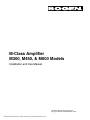
1
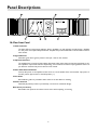
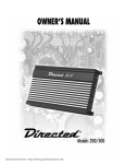
M-Class Amplifier
M300, M450, & M600 Models
Installation and Use Manual
© 2001 Bogen Communications, Inc.
All rights reserved. 54-2037-01R2 0109
Downloaded from: http://www.guardianalarms.net
Notice
IMPORTANT
Every effort was made to ensure that the information in this
guide was complete and accurate at the time of printing.
However, information is subject to change.
Important Safety Information
WARNING: To Reduce The Risk of Fire Or Electric Shock,
Do Not Expose This Apparatus To Rain Or Moisture.
Always follow these basic safety precautions when installing and
using the unit:
1.
2.
3.
4.
5.
6.
7.
8.
9.
10.
11.
12.
13.
Read these instructions.
Keep these instructions.
Heed all warnings.
Follow all instructions.
Do not use this apparatus near water.
Clean only with dry cloth.
DO NOT block any ventilation openings. Install in accordance with the manufacturer’s instructions.
Do not install near any heat sources such as radiators, heat
registers, stoves, or other apparatus (including amplifiers)
that produce heat.
Do not defeat the safety purpose of the polarized or
grounding-type plug. A polarized plug has two blades with
one wider than the other. A grounding-type plug has two
blades and a third grounding prong. The wide blade, or the
third prong, are provided for your safety. If the provided plug
does not fit into your outlet, consult an electrician for
replacement of the obsolete outlet.
Protect the power cord from being walked on or pinched,
particularly at plugs, convenience receptacles, and the point
where they exit from the apparatus.
Only use attachments/accessories specified by the manufacturer.
Unplug this apparatus during lightning storms or when
unused for long periods of time.
Refer all servicing to qualified service personnel. Servicing is
required when the apparatus has been damaged in any way,
such as power-supply cord or plug is damaged, liquid has
been spilled or objects have fallen into the apparatus, the
apparatus has been exposed to rain or moisture, does not
operate normally, or has been dropped.
Domestic and International Listings
UL and C-UL Listed.
CAUTION: TO PREVENT THE RISK OF ELECTRIC SHOCK, DO NOT REMOVE COVER (OR
BACK). NO USER-SERVICEABLE PARTS
INSIDE. REFER SERVICING TO QUALIFIED
PERSONNEL.
The lightning flash with arrowhead symbol, within an equilateral triangle, is intended to alert
the user to the presence of
uninsulated “dangerous voltage”
within the product’s enclosure
that may be of sufficient magnitude to constitute a risk of electric shock to persons.
The exclamation point within an
equilateral triangle is intended
to alert the user to the presence
of important operating and
maintenance (servicing) instructions in the literature accompanying the appliance.
Contents
Page
INTRODUCTION ..................................................................................................1
Package Contents................................................................................................................1
PANEL DESCRIPTIONS ....................................................................................2-3
M-Class Front Panel............................................................................................................2
M-Class Rear Panel ............................................................................................................3
INSTALLATION ..................................................................................................4-6
Installation Components....................................................................................................4
Ventilation ............................................................................................................................5
Rack Mounting ....................................................................................................................5
Table Mounting ....................................................................................................................5
Module Installation..............................................................................................................6
CONNECTIONS ....................................................................................................7
Speakers ................................................................................................................................7
Low-Impedance Speaker Connections ................................................................7
Earth Ground Terminal..........................................................................................7
70V “Transformer-Coupled” Speakers ................................................................7
BAL1S Module Input ..........................................................................................................7
Balanced Input Connections ................................................................................7
Unbalanced Input Connections ............................................................................7
OPERATION ......................................................................................................8-11
Controls & Connectors ................................................................................................8-9
Level Controls ........................................................................................................8
Sleep Mode Defeat ..............................................................................................8
Channel Balance....................................................................................................8
Lo-Cut Switch ........................................................................................................8
Effects Loop............................................................................................................9
Output Feeds..........................................................................................................9
Modes of Operation ....................................................................................................9-10
Stereo Mode ..........................................................................................................9
70V Mono Mode ................................................................................................10
Dual Mono Mode ..............................................................................................10
Audio Buses ........................................................................................................10
Modules ..............................................................................................................................11
Standard Input Module ......................................................................................11
Other Modules ....................................................................................................11
Module Priority ....................................................................................................11
Module Controls ..................................................................................................11
APPLICATIONS ..............................................................................................12-13
TROUBLESHOOTING ........................................................................................14
SPECIFICATIONS ................................................................................................15
Introduction
Bogen's M-Class amplifiers deliver on what professional sound installers need most: Flexibility, Power, and
Reliability.
Flexibility
The M-Class allows for the installation of up to 2 input modules, accepting inputs from microphones, telephone
systems, stereo sources, mono sources, or daisy-chaining of amplifiers. Each M-Class model comes standard with
a single, professional-quality, stereo, high-impedance balanced input module (BAL1S).
The M-Class has three operating modes to meet different installation needs - Stereo, Dual Mono, or 70V Mono.
Front panel controls allow independent operation of each power amplifier channel in stereo mode. In either
70V Mono or Dual Mono modes, the inputs form a 2:1 mixer with the front panel controls setting the signal
levels from each input. Prioritized input modules and 2:1 mixer operation allow the M-Class to supply the frontend signal processing required in paging systems and the power to cover any size installation.
Power
With three different models (M600, M450, and M300), the M-Class provides 2-channel operation at 600W,
450W, and 300W per channel into 4-ohm loads. Single channel, 70V Mono operation capacities are 1200W,
900W, and 600W. Along with being powerful, these amplifiers are also compact - using up only 2 rack spaces
(3-1/2") in a standard 19" rack.
Reliability
Driven by a conservatively-rated toroidal power transformer, these amplifiers are built for solid performance
with low distortion and a high slew rate. Output module circuitry is located away from input module circuitry,
minimizing noise and ground loops.The amplifiers require little maintenance and cleaning as internal electronic components are located outside of the forced air-stream flow. Front-mounted fan filters provide easy removal
and cleaning.
M-Class amplifers have a variety of electronic protection circuits including overcurrent, DC voltage, and thermal circuits. A special Clip/Limiting circuit continuously monitors the amount of distortion in the output signal
and reduces input levels as the amplifier approaches clipping. Back-Slope™, Bogen’s unique voltage stabilization
circuitry, regulates the AC energy supplied to the power toroid. This improves both system performance and
reliability despite varying AC supply conditions.
An energy-conserving sleep mode (defeatable) with instant-on return signal operation reduces wasted heat
production in paging systems with intermittent use. In addition, large output heatsinks and dual independentlycontrolled, high-output, variable speed fans provide superior cooling and quiet operation while reducing dust
accumulation.
Bogen's M-Class amplifiers are enclosed in a heavy-gauge steel chassis, which prevents mechanical damage to
the unit's internal components even if the unit is subjected to rough handling and excessive portable installations.The control knobs are located in a recessed section of the cast aluminum front panel to reduce the likelihood of mishandling and damage.The angled design of the amplifier's front panel allows easy finger access to
the front knob cover when the amplifiers are stacked tightly in a rack.
Package Contents
* M-Class Amplifier
* 2 Rack Ears
* 2 Filters and Grilles
* Instruction Manual
* Control Knob Cover
* BAL1S Input Module (pre-installed)
* 4 Rubber Feet & Screws
1
Panel Descriptions
M-Class Front Panel
1. Status Indicators
The Status LED is a multi-purpose indicator: Green - Amplifier is on and operating normally. Amber - Amplifier
is in low-power consumption Sleep Mode. Red - Amplifier has protected itself due to a fault condition. One for
each channel.
2. Signal Indicators
Illuminates green when signal is present at the input. One for each channel.
3. Clip/Limit Indicators
The amplifier limits currents and this indicator illuminates amber when there are excessive signal levels or very
low impedance output loads. A built-in Clip/Limiting circuit activates and reduces input signal levels when output distortion exceeds a few percent. One for each channel.
4. Power Switch/Circuit Breaker
Controls AC power to the amplifier and also works as a circuit breaker. If the circuit breaker trips, push it to
the OFF position (O) and then to the ON position ( l ).
5. Fan Grilles
Removable fan grilles are provided to allow access to the dust filters for cleaning.
6.Volume Controls
Detented (40 position) knobs are protected by a recess from mechanical damage.
Knob Cover (not shown)
Removable cover protects the volume controls from casual tampering or brushing.
2
Panel Descriptions
M-Class Rear Panel
1. Low-Impedance Outputs
Accepts up to #10 spade lugs for low-impedance speaker connections.
2. Channel Balance
Only active in Dual Mono mode. Allows one channel’s volume to be adjusted relative to the other channel.
3/4. Effects Loop In/Out
The effects loop connectors provide an insertion point for outboard signal processing equipment when the MClass is operating in either 70V Mono or Dual Mono mode, where inputs provide a 2:1 mixer function.
5/6. Output Feeds (Pre/Post-EQ)
Two different output feeds are provided that can supply signal to other audio equipment. Both outputs are
designed to feed high-impedance, unbalanced inputs of external equipment.The Pre-EQ Output Feed provides
a signal before any external signal processing.The Post-EQ Output Feed provides a signal that has been affected by the external signal processing equipment and the lo-cut filter.
7. Operational Mode Selector
The M-Class amplifer has 3 distinct modes of operation (Stereo; 70V Mono; Dual Mono) that are designed to
provide a wide range of application coverage. For a description of the different modes, see the Operation section of this manual.
8. Fan Exhausts
Two independent, variable speed cooling fans respond as needed to keep the amplifier cool and reduce dust
build-up.
9. 70V Mono Speaker Output
For 70V constant voltage speaker systems. Provides a single channel of amplification.
10. Chassis Ground
Provides convenient access to earth ground.
11. Lo-Cut Switch
Select a low-frequency roll-off of 65Hz or 125Hz for transformer-coupled and horn speakers. Flat position
allows full low-frequency performance.
12. BAL1S Input Module
Provides a balanced high-impedance input for each channel.The BAL1S Input Module is included standard with
the amplifier.
13. Module Bay
Accepts one or two Bogen input modules (BAL1S included with amplifier).
3
Installation
Installation Components
1. Rack Ears
Prior to installing the amplifier, you will need to attach the installation rack ears if you intend to install the amplifier in a rack and complete the setup process.
Remove the 6 front most cover screws on each side panel of the amplifier and attach rack ears as shown.
2. Dust Filter
Insert the dust filter into the fan grille before attaching the fan grille to the amplifier.
Filter Maintenance
Dust filters are provided with the M-Class amplifier to reduce the build up of dust on the heatsinks. Periodic
cleaning should be done when there is a noticeable build up of dust on the filters. To clean the filters, remove
them from the grilles and wash, vacuum, or tap them out. Promptly replace them.
Caution:
The fan blades are accessible when the grille cover and filter are removed.
Be careful not to place your finger or other objects into the fan.
3. Fan Grille
To insert or replace the grilles, first insert the tabs on the wider end of the grille in to the notches in the front,
center casting. Snap the other end of the grille in to the snap slots. Check that the grille is securely in place. To
remove, pry the end of the cover closest to the rack ears up until the snap tabs disengage.
4. Knob Cover
To protect the amplifier controls from casual tampering, the volume level controls are concealed behind a
removable cover. The cover snaps into place with tabs at the top and bottom. To remove the cover, squeeze
both ends of the cover, then gently dislodge the top and then the bottom. Be careful not to tip the top of the
cover too far forward while removing or the snap-in tabs could be damaged.To replace, simply snap it back into
place.
4
Installation
Ventilation
The M-Class was designed to be placed on a table or rack-mounted. When rack mounting, the amplifiers can
be stacked one on top of the other for maximum use of the rack.
An open air space of at least 4" must be provided at the front air intakes of the amplifier and the rear exhaust
must have at least 4" between itself and obstructions to ensure adequate cooling. This applies to both rackand table-mounted amplifiers.
Care should also be taken to ensure that the front intake air is not considerably warmer than the ambient air
temperature. Mount the amplifiers low in the rack so that heat dissipation from other equipment does not
warm the amplifier's intake air.
Rack Mounting
Rack ears are included with the amplifier to allow mounting in 19" racks. Attach the rack ears as shown in
Installation Components section. If any feet have been attached to the bottom of the amplifier, remove them. Load
the amplifier into the rack and secure it to the rack with appropriate hardware (not included).
Table Mounting
Feet are provided with the amplifier to allow it to be placed on a tabletop. Attach the included feet to the bottom of the amplifier as shown. Attachment of the rack ears to the unit is optional and purely aesthetic.
5
Installation
Module Installation
Installation
Two input module bays are available to accept various Bogen input modules thereby allowing users to customize
the amplifier to suit the needs of the installation. First read the instructions included with the module and make
the desired jumper setting changes before installing the module.The input modules are installed by simply sliding them along the card guides inside the module bays until the faceplate firmly sits against the M-Class chassis, then use the two screws supplied with the module to secure it to the chassis.
BAL1S Module Priority Jumper
The BAL1S module that comes standard (and pre-installed) with the M-Class differs in priority capability from
other Bogen input modules.This module is always the lowest priority since it is incapable of muting other modules. It can also be set so that it does not respond to muting from other modules and is, therefore, always on
for use in mixing applications.The module jumpers should be set prior to installing the module.The sleep switch
should be set to the desired position prior to installation of the right module (see Operation, Sleep Mode Defeat).
6
Connections
Speakers
Low-Impedance Speaker Connections
When the amplifier is set to either the stereo mode or the Dual
Mono mode (see Operation section), low-impedance speakers can be
connected to either the "A" or "B" speaker output terminals. The
amplifier is designed to work into speaker load impedances as low as
3.2 ohms.
The speaker terminals can accept up to a #10 spade lug and have integral clamping plates which make wiring easier.The polarity of each set of speaker outputs (A & B) is indicated
with a "+" and "-" sign. Use these indicators to ensure that the phasing of the speakers are correct. Do not
ground the "+" output of either set of outputs. Doing so will cause the amplifier to go into protect mode, shutting down operation of the affected channel.
Note:
The "+" and "-" indicators are mirrored on "A" and "B" outputs. Be sure to make the correct connections.
Earth Ground Terminal
The earth ground terminal is provided as a convenient means to connect to the amplifier’s chassis/AC ground, if necessary. DO NOT connect the earth ground terminal to the "+" terminals of either output.
No damage will occur if this is done, but the amplifier will go into protect mode and shut down the effected channel.
70V "Transformer-Coupled" Speakers
The 70V speaker output terminals are only usable when the amplifier
is in the 70V Mono mode (see Operation section). In this mode, both
channels are bridged into a single mono channel. Use only speakers
that are designed to work with 70V audio systems when connecting
to these terminals.The speaker terminals can accept up to a #10 ring
lug and have integral clamping plates which make wiring easier. The
70V output terminals are indicated by a yellow field above them.The
polarity of the output terminals is indicated for speaker phasing purposes. These output terminals must float and cannot be referenced to earth ground, so if they become grounded, the amplifier will go into protect mode, shutting down operation of the amplifier even though no damage
to the amplifier will occur.
BAL1S Module Input
Balanced Input Connections
Balanced input connections are used when the source device provides a balanced output (signal "+", signal "-", and ground "G").This
type of connection is desirable when operating in electrically noisy
environments, where long input cable runs are needed, or to
ensure the lowest noise operation. If compatible with the source
device, this type of connection is recommended.
Unbalanced Input Connections
When the source device provides only an unbalanced output
(signal and ground), the BAL1S input should be wired with "-"
input shorted to ground (G). The unbalanced signal's shield
wire is connected to BAL1S ground and the signal hot wire is
connected to the "+" terminal. Since unbalanced connections
do not provide the same amount of noise immunity that a balanced connection does, the connection distances should be made as short as possible.
7
Operation
Controls & Connectors
Level Controls
The front-mounted level controls act differently depending on the mode of operation.
In the stereo mode, each level control determines the volume of the corresponding
amplifier channel as in a typical amplifier. In the 70V Mono and Dual Mono modes, the
controls have a different function and determine the mix of the signal levels from the
different input modules (input modules can be assigned to either the "A" or "B" channel by the jumpers on the module).The front level controls determine the mix of the
two input module signals. They do not control the volume level of each amplifier in
these modes. Essentially, the volume level of both amp channels is fixed at maximum and the overall level of
the mixed input module signals determine the output volume level.To increase the overall volume of the amplifier output, turn up both front panel controls by the same amount.This increases the signal level of each module's input into the amplifier while keeping the mix the same. Similarly, turn down both controls to the same
knob position to reduce the overall output volume from the amplifier.
Sleep Mode Defeat
The M-Class amplifier includes a sleep mode feature that
greatly reduces the power consumption of the amplifier
after it has been idle for more than 3 minutes. Any audio
activity present at the input will wake the amplifier up
instantaneously so that there is no loss of audio. A sleep
mode switch located in the upper right hand corner of the
module bay can be set to activate or deactivate this feature
using a thin, flat-bladed screwdriver. (If a module is inserted
in the right bay, turn off the power and remove the module
before proceeding.) If the sleep feature is desired, make sure
the switch is in the down position. If the sleep feature is not
desired, make sure the switch is in the up position.
Channel Balance
Channel Balance only works in the Dual Mono mode of operation. In Dual Mono
mode, both amplifier channels get the same audio program at the same level.
To provide some direct control over the amplifier volume levels, a Channel Balance
control is provided.This control allows the adjustment of one amplifier channel output volume over the other.To reduce the volume level of channel "B" while leaving
channel "A’s" volume unchanged, the Channel Balance control is rotated counterclockwise. The diminishing
arrow with the "B" next to it indicates that rotating the control in that direction diminishes the "B" channel volume. Likewise for reducing channel "A" volume. Putting the control at the center of rotation allows equal, and
maximum, volume from both channels.
Lo-Cut Switch
The M-Class amplifier is a direct-coupled amplifier, which means that there are no output transformers used to deliver the 70V audio to the speakers. Because of this, the
M-Class amplifier has a Flat frequency response below 20Hz. This extended low frequency operation can be troublesome for some transformer-coupled speakers typically used in 70V audio systems. The relatively inexpensive transformers used in these
speakers cannot handle frequencies much below 60Hz.When frequencies lower than this are applied to these
speaker's transformers, they can saturate causing distortion and high instantaneous power consumption.
The Lo-Cut filter allows a low frequency roll-off to be introduced into the output signal preventing the speakers from receiving too much low frequency content.The 65Hz position should be used for all transformer coupled cone type speakers.The higher frequency roll-off of 125Hz provides an extra level of safety for horn speakers. Some horn speakers can be adversely affected by frequencies below 120Hz since they are designed to
reproduce higher frequency signals.
8
Operation
Effects Loop
The effects loop connectors act as an insertion point for outboard signal processing
equipment when the M-Class is operating in either the 70V Mono or Dual Mono
modes. In these modes, the inputs and front panel controls form a 2:1 mixer. Connect
the Effects Loop Out to the input of the external signal processing equipment. Connect
the Effects Loop In to the output of the external signal processing equipment. Inserting
an RCA jack into the Effects Loop In connector will automatically disconnect the input module signals from the
power amp stage so it can be routed through the external equipment. Removing the jack from the Effects Loop
In connector will reestablish the direct connection of the input modules to the power amp stage. The Effects
Loop signals are quasi-balanced, which means that they are intended for use with unbalanced equipment but
will improve the noise immunity. However, it is still a good practice to keep these connections as short as possible.
Output Feeds
Two different output feeds are provided that can supply signal to other amplifiers and
audio equipment. Both outputs are designed to feed high-impedance, unbalanced inputs
of external equipment.The outputs are also quasi-balanced for better noise immunity,
but connection lengths for these outputs should still be kept as short as possible.The
Pre-EQ Output Feed provides the signal before any external signal processing effects it.
The Post-EQ Output Feed provides a signal that has been affected by the external signal processing equipment
and lo-cut filter. Depending on the application, it may be more desirable to use the externally-processed signal
rather than the raw version of the signal.
Modes of Operation
Stereo Mode
Placing the 3-position switch to its left most position puts the
amplifier in the stereo mode of operation.The amplifier supplies
two independent channels of low-impedance amplification in
this mode (see Stereo Mode Block Diagram).These channels can
be used to supply left and right audio for stereo installations of
2 separate zones of amplification with different audio programs.
When using the supplied BAL1S input module in this mode, the
input applied to the "A" input will be controlled by the "A" level control and the output will be available on the
"A" channel speaker terminals. Likewise for the "B" channel.When using other modules, there are jumper settings that allow those modules to apply signal to the "A" or "B" channels, or both. See the application examples
for more information on how to use the two audio buses.
Stereo Mode Block Diagram
9
Operation
70V Mono Mode
Placing the 3-position switch to its right most position puts
the amplifier in the 70V Mono mode of operation. The
amplifier supplies a single channel of amplification in this
mode (see 70V Mono Mode Block Diagram). This mode also
mixes the signals from each input module into a mono program. Input signals of modules that are assigned to the "A"
bus are controlled by the "A" level control on the front of
the unit and likewise for modules whose outputs are
assigned to the "B" bus. By assigning each module to a different bus, a 2:1 mixer is formed with the front-mounted level controls adjusting the mix. Additionally, one module can be set to mute the other when it is active,
thereby providing an effective paging system (see the section on Module Priority). It is important in this mode to
set the assignment jumpers on the two input modules so that their outputs are on different audio buses (see
the section on Audio Buses). Speakers must be correct for 70V operation. (See section on 70V “TransformerCoupled” Speakers).
70V Mono Mode Block Diagram
Dual Mono Mode Block Diagram
Dual Mono Mode
Placing the 3-position switch to its center position puts the
amplifier in the Dual Mono mode of operation.This mode is
similar to the 70V Mono mode except that the amplifier
supplies two channels of low-impedance amplification in this
mode (see Dual Mono Mode Block Diagram). This mode still
mixes the input signal from the different modules but a
Channel Balance control is provided to adjust the output
levels of one channel against the other (see the section on
Channel Balance). It is important in this mode to set the assignment jumpers on the two input modules so that
their outputs are on different audio buses (see the section on Audio Buses). Speakers must be low-impedance
type, not 70V type.
Audio Buses
The M-Class amplifier contains two separate audio buses.The "A" bus level is adjusted by the "A" level control
on the front of the unit and the "B" bus is adjusted by the "B" Level control. Most Bogen modules provide a
means to assign their output to either or both of the audio buses.The instructions that accompany the modules will describe the jumper settings for these assignments.When using the M-Class amplifier in either the 70V
Mono or Dual Mono modes, the module signals will be mixed (see 70V Mono Mode under the Operation section of the manual). For maximum control when mixing signals, it is important that each of the two input modules be set so that the outputs feed different audio buses. Otherwise, proper mixing of the signals will be difficult. Check that each module is set to a different audio bus before installing it.
10
Operation
Modules
Standard Input Module
The BAL1S has a priority jumper that can set the module to be muted by any other modules installed or to
never mute.When signaled to mute by another module,
the BAL1S will reduce the level of both channel’s input
signals by the amount set by the ducking control
(DUCK). When the mute is released, the module will
fade the input signal levels back to the previous level.
BAL1S
G
BAL IN A
DUCK
G
BAL IN B
The M-Class is shipped with one input module, the
BAL1S, pre-installed.The BAL1S provides 2 high-impedance, balanced, low-noise inputs.This module provides a
standard 2-channel amplifier input, but can be replaced
by other modules if desired. The input’s connectors,
labeled A & B, correspond to the similarly marked rear
speaker connections and front panel controls. The
BAL1S inputs are permanently assigned to their respectively-labeled audio buses.
Other Modules
Various modules can be installed in the M-Class amplifier. Refer to the instructions that come with each module for specific connection and setup information.
Module Priority
Bogen input modules allow for up to 4 levels of priority. Each module (except the BAL1S, which comes standard with the amplifier) can both be muted by higher priority modules and mute lower priority modules. The
priority level of the module is set by the position of 2 jumpers on each module.
Note:
Even though 4 priority levels are available on the Bogen input modules, only two levels can be used with
the M-Class since it only accepts 2 modules.
It does not matter which priority level is set on the module, only that the intended higher priority module be
set to some priority level that is higher than the intended lower priority module. However, Bogen recommends
using Priority Level 1 (the highest available) for the higher priority module and Priority Level 2 for the lower
priority module.
Module Controls
Each input module type has a number of controls such as Gain, Bass, and Treble.These controls affect the operation of the amplifier as much as the ones mounted on the amp. Be sure to read the instructions with each
module and be aware of its control setting when adjusting the overall operation of the amplifier.
11
Applications
Application Examples
Application 1:
Simple 1-Zone, 70V Mono telephone paging system with background music
Background music plays through the system when no page is being made. During a telephone page, the background
music mutes to a predetermined level and the telephone page is heard.When the page is complete, the background
music fades back to its previous level.
Mode of Operation: 70V Mono
Amplifier Adjustments: Volume of the telephone page is adjusted by the "A" Level Control, background music level is
adjusted by the "B" Level Control. Set the Lo-Cut switch to 65Hz.
Module Adjustments:Adjust Gain to make each source’s input level similar.Adjust Bass & Treble (where applicable) to
your preference. Adjust ducking control on MAX1R for desired level. Adjust Gate controls of TEL1S for optimum
paging control.
Application 2:
Stereo low-impedance music system with microphone override
Stereo program material plays into low-impedance speakers. When the microphone becomes active, the stereo
music is muted to a predetermined level and the microphone is easily heard.When the microphone signal stops, the
music fades back to its previous level.
Mode of Operation: Stereo
Amplifier Adjustments: Stereo music program wired to BAL1S inputs. Each stereo channel volume is controlled by the
associated front level control. Microphone level is also affected by changes in these level controls, but is to be mainly set by the Gain control on the MIC1X module. Not applicable in stereo mode.
Module Adjustments:Adjust Gain of MIC1X to desired paging level. Adjust Bass & Treble of MIC1X module to appropriate level. Adjust Gate controls of MIC1X for optimum paging control. Adjust ducking control on BAL1S for
desired mute level.
12
Applications
Application 3:
Global music/message buffered and distributed to multiple amps with local override input for each amplifier.
Similar to the paging situation found at airport departure gates, global music/messages play when no local page is
present. During local page (from departure gate microphone), music/message mutes to predetermined level and
page is heard only in local area. When local page is complete, global music/message fades back to previous level.
During local zone page, global music/message mutes only in local area, then fades back. Buffered global music/message signal is unaffected by local paging condition.
Mode of Operation: 70V Mono or Dual Mono
Amplifier Adjustments:Volume of local (departure gate) MIC is adjusted by the "A" Level Control. Global music/message source is adjusted by the "B" Level Control. Set Lo-Cut or Channel Balance, depending on mode of operation.
Module Adjustments:Adjust Gain to make each sources input similar. Adjust Bass & Treble (where applicable) to your
preference.Adjust Ducking on BRG1R for desired level. Adjust Gate control on MIC1X for optimum paging operation.
Application 4:
2 mono zones, low-impedance speakers, telephone paging and background music. Zones have significantly
different volume levels
Background music plays through the system when no page is being made. One zone is low volume while the other
is high volume. During a telephone page, the background music mutes to a predetermined level and the telephone
page is heard at correct volume level for each zone.When the page is complete, the background music fades back
to its previous level.
Mode of Operation: Dual Mono
Amplifier Adjustments: Volume of the telephone page is adjusted by the "A" Level Control. Background music level is
adjusted by the "B" Level Control. Set the Lo-Cut switch to Flat or 65Hz. Channel Balance control on rear of amplifier adjusts the volume level of one speaker zone over the other zone. Rotate the Channel Balance control towards
the "B" marking (counterclockwise) to reduce the volume level of the speakers connected to the "A" output terminals while leaving the volume level of "B" speaker output unchanged.
Module Adjustments: Adjust Gain to make each source’s input level similar. Adjust Bass & Treble (where applicable)
as appropriate. Adjust ducking control on MAX1R for desired level. Adjust Gate controls of TEL1S for optimum
paging control.
13
Troubleshooting
PROBLEM
CONDITION
CAUSE
Status LED is off.
• Amplifier not plugged in.
• AC outlet dead.
• Power switch off.
• Breaker (power switch) tripped.
- Turn off, then turn back on.
Status LED is green.
Signal LED is off.
• Level controls turned down.
• No signal from source.
• Input module jumpers in wrong bus configuration (if available).
Status LED is green.
Signal LED is green.
Clip/Limit LED is off.
• 70V mono connections on amplifier incorrect.
• Poor/broken speaker wiring.
• Defective speakers.
DISTORTED
SOUND
Status LED is green.
Signal LED is green.
Clip/Limit LED is off.
• Input signal level too high.
• Poor speaker connections.
• Lo-cut switch set to Flat (70V mono system only).
POOR
LOW-FREQ.
RESPONSE
(NO BASS)
Status LED is green.
Signal LED is green.
Clip/Limit LED is off.
• Lo-cut switch setting.
• Speaker wiring phasing.
• Module bass control setting (if available).
Status LED is red/green cycling.
• DC level at signal input.
• Load impedance too low.
• Amplifier speaker output is short-circuited.
• Amplifier too hot (check for proper ventilation clearances).
Status LED is green.
Signal LED is green.
• Poor electrical connections at input.
• Input cable routed near AC cables, power transformer, or
other EMI radiating devices.
• Electrically noisy devices operating on the same AC circuit.
• Poor equipment grounding.
- Ensure that all AC safety grounds are connected.
- Make sure that all components in audio chain are tied to the
same ground.
NO SOUND
INTERMITTENT
OPERATION
NOISE/HUM
14
Specifications
M600
M450
M300
Power Output
70V mono
4-ohm
8-ohm
1200W @ 4 ohms
600W per channel*
400W per channel*
900W @ 5.5 ohms
450W per channel*
300W per channel*
600W @ 8 ohms
300W per channel*
200W per channel*
Input Sensitivity
1.225V
1.06V
0.866V
S/N Ratio (20K BW)
109dB ref. 8 ohms, F.P.
106dB ref. 8 ohms, F.P
103dB ref. 8 ohms, F.P
Class of Operation
H
H
AB
Product Weight
46 lbs.
44 lbs.
41 lbs.
Connectors: AC Power
20A line cord
15A line cord
Output
5-pin "touch-proof" Barrier Strip, RCA Pre- & Post-EQ Output
Power Bandwidth
20-40kHz .5% THD
THD @ 1kHz rated power
less than .02%
Load Impedance
4-8 ohms, 70V
Minimum Load Impedance (Stereo)
3.2 ohms
Frequency Response @ 1 watt
Output Regulation,
20-20KHz +/- 0.25dB
1kHz direct
0.5dB @ 8 ohms
1kHz bridged
Inputs
1.5dB @ 70V
BAL1S Standard, other modular input types available
AC Input Voltage Range
95-130V AC, 60 Hz
Indicators
Status (On/Protect/Sleep), Clip/Limit, Signal
Temperature Range
15 to 105 degrees F
Cooling
Forced Air Variable Speed Fan
Physical Dimensions (W x H x D)
Protection
Special Features
15A line cord
17" x 3.5" x 16"
RF, DC, Low-frequency,Thermal, Low-impedance, Circuit Breaker, Short Circuit
Sleep Mode, Back-Slope regulation, Stereo, Dual Mono,
70V Mono Operation,Toroidal Power Transformer
* Both channels driven at nominal line voltage 120V AC 60Hz.
15
50 Spring Street, Ramsey, NJ 07446, U.S.A.
Tel. 201-934-8500, Fax: 201-934-9832
Web Site: www.bogen.com / E-mail: [email protected]