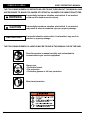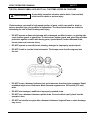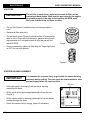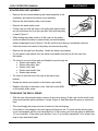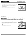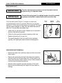
1
633GC
OPERATOR’S MANUAL
© 2007 ICS, Blount Inc.
P/N 70944 Jan 07
633GC OPERATOR’S MANUAL
TABLE OF CONTENTS
SYMBOLS & LABELS
4
SAFETY
5
TECHNICAL SPECIFICATIONS
8
SET-UP
9
OPERATION
12
MAINTENANCE
17
TROUBLESHOOTING
25
REFERENCE
26
P/N 70944 Jan 07
© 2007 ICS, Blount Inc.
SYMBOLS & LABELS
633GC OPERATOR’S MANUAL
THE FOLLOWING SYMBOLS & DEFINITIONS ARE FOUND THROUGHOUT THIS MANUAL AND
ARE DESIGNED TO MAKE YOU AWARE OF POTENTIAL HAZARDS OR UNSAFE PRACTICES.
WARNING
A potentially hazardous situation exists which, if not avoided,
could result in death or serious injury.
CAUTION
A potentially hazardous situation exists which, if not avoided,
may result in minor or moderate injury or property damage.
IMPORTANT
A potential situation exists which, if not avoided, may result in
product or property damage.
THE FOLLOWING SYMBOLS & LABELS MAY BE FOUND IN THIS MANUAL OR ON THE SAW
Read the operator’s manual carefully and understand the
contents before you use this equipment.
Always use:
• Protective helmet
• Ear protection
• Protective glasses or full face protection
Wear hand protection
© 2007 ICS, Blount Inc.
P/N 70944 Jan 07
633GC OPERATOR’S MANUAL
SAFETY
THE FOLLOWING SYMBOL APPLIES TO ALL THE ITEMS LISTED ON THIS PAGE
WARNING
A potentially hazardous situation exists which, if not avoided,
could result in death or serious injury.
Chain breakage can result in high-speed ejection of parts, which can result in death or
serious personal injury to operators or bystanders. The items listed below are critical to
minimizing the risk of chain breakage and injury.
• DO NOT operate a diamond chainsaw with a damaged, modified, broken, or missing side
cover, bottom guard, or guard flap. The side cover, bottom guard, and guard flap provides
protection against contact with moving parts, ejected debris, broken diamond chain,
thrown water and concrete slurry.
• DO NOT operate a saw with loose, missing, damaged or improperly repaired parts.
• DO NOT install or run the chain backwards. The bumper must lead the segment into
the cut.
• DO NOT insert a diamond chainsaw into a slot narrower than the chain segments. Rapid
pushback might occur. Reference: Most diamond segments are .225 inches (5.72 mm)
wide.
• DO NOT use damaged, modified or improperly repaired chain.
• DO NOT run a diamond chainsaw upside-down. Concrete debris can fly back into the
operator’s face.
• DO NOT cut ductile iron pipe with a diamond chainsaw. Segment loss or chain breakage
may occur.
P/N 70944 Jan 07
© 2007 ICS, Blount Inc.
SAFETY
633GC OPERATOR’S MANUAL
THE FOLLOWING SYMBOL APPLIES TO ALL ITEMS LISTED ON THIS PAGE
CAUTION
A potentially hazardous situation exists which, if not avoided,
may result in minor or moderate injury or property damage.
• Always turn a diamond chainsaw OFF when performing maintenance on the saw
including chain tensioning.
• Never use equipment that is not functioning properly. Have the saw repaired by qualified
service personnel.
• Turn engine OFF before refueling. Keep away from open flame. Always provide adequate
ventilation when handling fuel. Move diamond chainsaw at least 10 feet (3 m) away from
refueling area before starting.
• SealPro® diamond chains require a minimum water pressure of 20 psi (1.4 bar).
Insufficient water supply may result in excessive wear to the chain, which can lead to
loss of strength and chain breakage.
• Never start a diamond chainsaw unless the bar, chain and
side cover are properly installed.
GENERAL SAFETY PRECAUTIONS
• Always wear protective clothing, including hard hat, eye protection, hearing protection, and
gloves.
• Avoid loose fitting clothing.
• Perform safety checks before starting each day.
• Always operate tool with solid footing and with both hands on saw.
• Remove or control slurry to prevent slippery conditions while cutting.
• Be sure there are no obstructions (plumbing, electrical conduit, air ducts) and no unnecessary
people present.
• Set up a well-marked safety zone with a roped boundary and clear signs.
• Provide adequate ventilation when working in an enclosed area. Breathing exhaust gases is
dangerous.
• To avoid electrocution, check for live electrical wiring near cutting area.
© 2007 ICS, Blount Inc.
P/N 70944 Jan 07
633GC OPERATOR’S MANUAL
SAFETY
THE FOLLOWING SYMBOL APPLIES TO ALL ITEMS LISTED ON THIS PAGE
IMPORTANT
A potential situation exists which, if not avoided, may result in
product or property damage.
Note: The diamond chainsaw is equipped with a two-stroke engine and must always be
run using a mixture of gasoline and ICS® two-stroke engine oil. It is important to accurately
measure the amount of oil to be mixed to ensure that correct mixture is obtained. When
mixing small amounts of fuel, even small inaccuracies can drastically affect the ratio of the
mixture.
• This engine is designed to be operated on premium unleaded gasoline.
• Use high quality, unleaded gasoline with a minimum octane rating of 90. If lower octane
gasoline is used, engine temperature will increase which will result in a piston seizure
and damage to the engine.
• Fuel mixture: 25:1 gasoline/oil mixture. Incorrect fuel mixture is the number one cause of
piston seizure.
• Use ICS® brand two-stroke engine oil, or other high quality 2-stroke oil that has been
formulated for air cooled power equipment.
• Never use two-stroke oil formulated for water-cooled two-cycle engines, such as
outboard motor oil.
• Never use motor oil intended for four-stroke engines.
ENGINE BREAK-IN
• It is very important to break-in a new engine to “seat” all moving parts, especially the
piston rings.
• To break-in the engine, run one full tank of 25:1 fuel at idle, cycling the throttle every
5 to 10 minutes to prevent loading.
• Failure to break-in an engine may result in piston seizure.
P/N 70944 Jan 07
© 2007 ICS, Blount Inc.
TECHNICAL SPECIFICATIONS
633GC OPERATOR’S MANUAL
Engine Type
2-stroke, Air Cooled
Displacement
101cc (6.2 cu in)
Horsepower
6.5 HP (4.8 kw) @ 8700 RPM
Engine Speed
11,500+/-500 RPM, Mechanically
governed
Diamond Chain Speed
4,950 fpm (25m/s), free running
Idling Speed
2800-3200 RPM
Weight
27.5 lbs (12.5kg) with guide bar and
diamond chain
Cut Depth
14 in (36cm) & 16.2 in (41cm)
Bar Lengths
14 in (36cm) & 16.2 in (41cm)
Carburetor
Walbro WGAK3, Throttle shaft sealed,
Ignition
Selettra electronic – Water resistant
Clutch
Centrifugal, three shoe, single spring
Fuel ratio
25:1 gasoline-to-oil
Fuel Capacity
34 oz (1 Liter)
15-18 minutes run time per tank
Water Supply
Minimum 20psi (1.5 bar)
Water Flow
Minimum: 2 gpm (8 lpm)
Noise Level
102dB at 3 ft (1m)
Vibration Level
8 meters/sec2 (front handle)
Engine Break-in Period
One tank, without cutting, cycling
throttle
Spark Plug
Champion CJ7Y or Bosch BWS7F
© 2007 ICS, Blount Inc.
P/N 70944 Jan 07
633GC OPERATOR’S MANUAL
SET-UP
GUIDE BAR AND DIAMOND CHAIN INSTALLATION
STEP 1
Loosen side cover nuts and remove side
cover.
STEP 3
Mount the diamond chain on the guide bar
starting at the drive sprocket and continue
over the guide bar nose.
Install the diamond chain correctly.
If using a single bumper chain, the
bumper must always lead the segment
into the cut as shown here.
STEP 2
Place bar onto studs and chain adjustment
pin.
STEP 4
Install the side cover.
P/N 70944 Jan 07
© 2007 ICS, Blount Inc.
SET-UP
633GC OPERATOR’S MANUAL
GUIDE BAR AND DIAMOND CHAIN INSTALLATION
3/4" (18 mm)**
** As measured without pulling
downward (eg. hanging by gravity)
STEP 5
Make sure all the drive links are inside
the guide bar groove then lift the bar nose
and tension the chain by turning the screw
clockwise.
STEP 6
If the chain is too loose, it could come off
the bar, or it will allow the drive sprocket to
spin without turning the chain, which can
chew up the chain drive links. If the chain
is too tight, a lot of the saw’s power goes
into turning the chain rather than into the
cut. In extreme over-tightened cases, the
saw may not be able to turn the chain at
all. In addition, damage can occur to the
bar nose and premature stretch may occur.
See Note 1.
10
© 2007 ICS, Blount Inc.
STEP 7
All chains have a tendency to stretch
when used. Diamond chains stretch more
than wood cutting chains because of the
abrasive materials they are cutting. When
a chain stretches to a point where the drive
links are hanging approximately 1/2”
(12 mm) to 3/4” (18 mm)** below the bar,
it’s time to tension the chain. See Note 2.
STEP 8
Before cutting, check for proper tension by
pulling the chain around the bar by hand. If
you cannot easily pull by hand, the chain is
too tight and needs to be loosened a little.
See Note 3.
P/N 70944 Jan 07
633GC OPERATOR’S MANUAL
SET-UP
GUIDE BAR AND DIAMOND CHAIN INSTALLATION
STEP 9
Continue to lift up on the nose of the guide
bar and firmly tighten the side cover nuts.
NOTE: To prevent chain tensioner
breakage, be sure the side cover nuts
are tightened to approximately 20 ft-lbs
(27 Nm).
STEP 10
Attach to water source with pressure of not
less than 20 psi (1.4 bar).
Note 1: Be aware that the guide bar rails may develop sharp edges over time so always pull the
diamond chain by the diamond segments.
Note 2: Do not “over tension” the diamond chain. Loss of power will result. It is normal for the
drivelinks to hang underneath the guide bar. The diamond chain should be tight but be able to be
pulled around the guide bar by hand.
Note 3: To prevent chain tensioner breakage, be sure the side cover nuts are tightened to
approximately 20 ft-lbs (27Nm).
P/N 70944 Jan 07
© 2007 ICS, Blount Inc.
11
OPERATION
633GC OPERATOR’S MANUAL
FUEL HANDLING
CAUTION
FUEL MIXTURE: 25:1 gasoline/oil mixture.
GASOLINE
OIL
GASOLINE
OIL
US
Gallon
1
2 1/2
5
US
Fl oz
5.2
12.8
25.6
Liters
1
5
10
20
ml
40
200
400
800
• Use premium unleaded gasoline with a minimum octane rating of 90. If lower octane gasoline is
used, engine temperature will increase which can result in a piston seizure and damage to the
engine.
• Always provide adequate ventilation when handling fuel.
• Use caution when handling gasoline. Avoid direct contact with skin or inhaling fuel vapor.
FUEL MIXING
• Always mix gasoline and oil in a clean container intended for use with fuel.
• Keep fuel container closed tightly to prevent moisture from getting into the fuel.
• Always begin mixing fuel by adding half the amount of gasoline to be used. Then add the correct
amount of two-stroke oil for 25:1 mixture and finish filling the container with gasoline.
• Do not mix more than one month’s supply of fuel. This helps prevent the separation of the
two-stroke oil from the gasoline (varnishing).
• If the saw is not used for an extended period of time (3 months) the fuel tank should be emptied
and cleaned.
FUELING
• Always shut off the saw before fueling.
• Before fueling, clean the area around fuel cap to prevent dirt from contaminating the fuel.
Contamination of the fuel tank can lead to saw malfunction.
• Thoroughly mix the fuel in it’s container before fueling.
• Slowly open the fuel cap to release any pressure that may have built-up in the tank.
• After adding fuel, tighten the fuel cap carefully and secure with a wrench.
12
© 2007 ICS, Blount Inc.
P/N 70944 Jan 07
633GC OPERATOR’S MANUAL
OPERATION
STARTING AND STOPPING A DIAMOND CHAINSAW
WARNING
Never start a diamond saw without the bar, chain and side cover
properly assembled. Otherwise, the clutch can come loose and
cause personal injuries.
CAUTION
Always move a diamond chainsaw at least 10 feet (3 m) away from
the fueling area before starting.
IMPORTANT
Place the diamond saw on clear ground. Ensure that secure
footing is established and chain is not contacting any objects.
COLD ENGINE STARTING PROCEDURE
1. Toggle the ignition switch to the "START" position and pull the
choke lever out.
C
2. Lock the throttle in the start position by depressing the trigger (A)
and trigger interlock (B) at the same time.
3. Depress and hold throttle lock button (C) while releasing the trigger
and trigger interlock in succession.
B
A
4. Open the water valve 1/4 turn.
5. Place the diamond chainsaw on the ground making sure the chain
is free of any obstructions.
6. Place right foot on the base of the rear handle.
Figure 1: a-Trigger, b-trigger
interlock, c-throttle lock
7. Place left hand on front handle.
8. With right hand, slowly pull starter handle until the starter pawls engage.
9. Pull the starter cord (hard, fast, short pulls) until engine fires or "pops" - should be 1 to 7 pulls.
10.Push the choke lever in.
11. Pull the starter cord until engine starts - should be 1 to 2 pulls.
12.When the engine starts, allow the engine to idle. Pull on the throttle trigger several times to help
warm up the engine.
13.Open the water valve completely.
WARM ENGINE STARTING PROCEDURE
1. Use the same procedure as starting cold engine, but DO NOT pull choke lever out. If choke is used, the
carburetor will flood with gas.
2. If the engine does not start in 3 hard, fast pulls with the throttle locked, unlock the throttle and pull the
starter cord 3 more times.
Note: To hold the trigger fully open it may be necessary to insert right foot into rear handle opening
and twist.
STOPPING THE SAW
•
To turn the engine off, toggle ignition switch to the "STOP" position. Close water valve.
P/N 70944 Jan 07
© 2007 ICS, Blount Inc.
13
OPERATION
633GC OPERATOR’S MANUAL
PRE-CUT CHECKLIST
• Proper Chain Installation: The bumper should lead the segment into the cut, double bumper
chains may be mounted in either direction.
• Proper Chain Tension: The chain should be tight but easily pulled around the guide bar by hand.
• Ensure all safety devices are properly mounted and functional and that all controls are in proper
working order.
• Be sure there are no obstructions (plumbing, electrical conduit, air ducts) and no unnecessary
people present.
• Always wear protective clothing, including hard hat, eye protection, hearing protection, non-slip
safety boots, and gloves. Avoid wearing loose fitting clothing.
• Adequate Water Supply and Pressure:
Minimum Flow: 2 gpm (8 lpm)
Minimum Water Pressure: 20 psi (1.4 bar)
• Diamond chains with SealPro® require a minimum
water pressure of 20 psi (1.4 bar).
IMPORTANT
The single most important factor an operator can control to
increase chain life is to use adequate water pressure. Insufficient
water supply will result in excessive wear to the chain, which can
lead to loss of strength and chain breakage.
PLANNING THE CUT
• Select the proper chain type for the material being cut.
• Outline the cut with a permanent marker for a visual cutting guide.
• Avoid pinching the guide bar and chain. Always cut the bottom of an opening first, then top, and
then the sides. Save the easiest cut for last.
• For the straightest cuts use the “Step Cut” method. First score the entire cut line approximately a
half-inch deep using the nose of the bar. Next, deepen the cut by about two inches. Then plunge
all the way through and complete the cut using the Wallwalker ®.
• Be sure cut concrete cannot fall and injure operator or bystanders. Concrete is very heavy,
one cubic foot = 12”x12”x12” = 150 lbs. (30cm x 30cm x 30cm = 68kg).
• Check for live electrical wiring near the cutting area or in the concrete to avoid electrocution.
14
© 2007 ICS, Blount Inc.
P/N 70944 Jan 07
633GC OPERATOR’S MANUAL
OPERATION
CUTTING WITH THE 633GC
To start a cut, hold trigger on full throttle and slowly plunge the nose of the bar straight into the wall.
Lengthen the cut and engage the point of the fixed Wallwalker ®. Use the fixed Wallwalker ® as a pivot
point and pull up on the rear handle to rotate the bar into the cut.
CUTTING TIPS
• Always operate the diamond chainsaw at full throttle. Apply enough feed force so that the free
running RPM drops 20 to 30%. If too much force is applied, the saw will lug or stall. The chain will
not have enough speed to cut effectively. If too little feed force is applied, the diamonds will skid
and glaze over.
• For straighter cuts use the “step cut” method. First score the entire cut line with the nose of the
guide bar approximately 1/2 inch (12mm) to 1 inch (25mm) deep. Next, deepen the cut by about
2 inches (50 mm). This groove will help guide the guide bar for a straight cut. Then plunge all the
way through and complete the cut using the fixed Wallwalker ®.
• Plunge cut instead of starting at the top of the wall. This will reduce chatter, extend diamond life,
create a straighter cut and more quickly enable the use of the Wallwalker ®.
• Use the fixed Wallwalker ® to help cut more efficiently
and reduce operator fatigue. The fixed Wallwalker ® is
a fulcrum that can be used to apply additional force
when cutting. To use correctly, plunge into the wall
and simply engage the point of the fixed Wallwalker ®
into the cut and pry upward with the rear handle.
WallWalker ® point
• As the saw begins to rotate up, feed force is developed
down the line of the intended cut. Once the saw is fully
rotated upwards, pull the saw out of the cut a few inches
and re-engage the pick into the cut and repeat.
• When cutting heavy rebar, slowly ”rock” the saw so that you’re always cutting concrete as well
as steel. This will help keep the diamonds exposed. Also, expect less chain life when cutting
heavy rebar.
• Expect more chain stretch when making nose buried cuts for extended periods of time, as the
chain does not have a chance to “throw” the slurry away from the nose of the bar.
• If the saw begins to cut consistently crooked, turn the bar over and use the other side. Dress
worn rails with belt sander. Note: The normal life of a guide bar is 2 to 3 diamond chains. Heavy
rebar can shorten guide bar life.
• When using a new chain, you can increase the cutting speed by “opening up the diamonds”.
Make a few cuts in an abrasive material such as a cinder block.
P/N 70944 Jan 07
© 2007 ICS, Blount Inc.
15
OPERATION
633GC OPERATOR’S MANUAL
SYSTEM CLEAN-UP
• After cutting, run the saw for at least 15 seconds with the water on to flush slurry and debris from
chain, bar and drive sprocket.
• Wash concrete slurry from saw assembly.
• Avoid getting any water in the carburetor or exhaust system. If water enters exhaust port, point
the bar tip down and pull the starter handle several times to expel water from muffler.
• Remove bar and chain. Flush out the chain tensioner with high water pressure and lubricate with
grease.
• After cleaning the saw, spray the entire saw body, chain, bar, and drive sprocket with lightweight
oil. Using lightweight oil on the saw will minimize rust and help reduce slurry build up.
16
© 2007 ICS, Blount Inc.
P/N 70944 Jan 07
633GC OPERATOR’S MANUAL
MAINTENANCE
Follow these simple maintenance guidelines
and the 633GC Concrete Cutting Saw will keep running at its very best.
AFTER EACH USE
1. Rinse the saw, guide bar and diamond chain with water.
2. Follow instructions on the Daily Maintenance Label, located on the air filter cover.
3. Inspect and tighten all fasteners as necessary.
4. Inspect drive sprocket for tooth wear and replace if tooth tips are pointed.
5. Inspect the starter cord. Replace if frayed.
6. Clean air filter. Inspect the air filter for holes. Replace as necessary.
7. Spray saw, guide bar, and chain with lightweight oil.
8. Grease the chain tensioner.
AFTER 10 HOURS OF USE
1. Remove the starter cover and lubricate the starter recoil spring. Clean the flywheel fins and the
starter pawls with a wire brush, then grease the starter pawls.
2. Remove the spark plug and clean with a wire brush. Check the electrode gap.
The correct gap is 0.020 inches (0.5mm).
AFTER 40 HOURS OF USE
1. Change the spark plug. Adjust the electrode to 0.020 inches (0.5mm).
2. Check the fuel filter located inside the fuel tank. Clean or replace if clogged
P/N 70944 Jan 07
© 2007 ICS, Blount Inc.
17
MAINTENANCE
633GC OPERATOR’S MANUAL
AIR FILTER
IMPORTANT
The air filter is made from a nylon micro mesh air filter and an
internal spit-back screen. Both must be kept clean for the engine
to operate properly. If the saw is not reaching full RPM, most
likely one or both of the air filters are dirty.
• The air filter (Figure 1) should be free of holes and white in
color.
• Replace air filter when dirty.
• The spit-back screen (Figure 2) should be free of holes and be
white in color. Clean with mild solvent or gasoline and dry with
high pressure air. If spit-back screen is dirty the saw will not
reach full RPM.
Figure 1
• During re-assembly, tighten air filter wing-nut "finger tight" plus
an 1/8" of a turn with wrench.
Figure 2
STARTER HOUSING ASSEMBLY
IMPORTANT
It is common for concrete slurry to get inside the starter housing
assembly during cutting. This can cause the starter pawls to stick
and not engage when the rope is pulled.
Oil port
• After each usage, thoroughly flush the starter housing
assembly with water.
• Oil the recoil spring by spraying lightweight oil into the port
(Figure 3).
• Oil the starter pawls by spraying lightweight oil into the starter
housing through the vents.
• Check the starter cord for fraying, replace if necessary.
Figure 3
18
© 2007 ICS, Blount Inc.
P/N 70944 Jan 07
633GC OPERATOR’S MANUAL
MAINTENANCE
STARTER ROPE REPLACEMENT
• Remove the four screws attaching the starter assembly to the
crankcase, and remove the starter cover assembly.
• Remove the three starter pulley cover screws.
• Remove the starter pulley cover.
• Pull the rope out until the notch in the pulley has made at least
two full revolutions and is at the rope inlet, then hold the pulley
in place (Figure 1).
Figure 1
• While holding the pulley in place, lift the rope into the pulley
notch and allow the pulley to unwind slowly (counterclockwise)
without wrapping the rope (Figure 2). Do this until the recoil spring is completely unwound.
• Undo the screw in the center of the pulley, and remove the pulley.
• Remove the old rope from the pulley. Retain the starter rope washer.
• Pry the starter rope retainer from the starter rope handle, and remove the old rope from
the handle.
• Tie a knot in one end of the rope and thread the rope through the:
o Starter rope washer, then
o Starter rope pulley, then
o Starter cover, then
o Starter rope handle, then
o Starter rope retainer
• Tie a knot to lock the end of the rope in the starter rope
retainer.
• Reseat the starter rope retainer in the starter rope handle.
• Replace the pulley in the starter cover. Use blue Loctite #242
on the starter pulley screw.
Figure 2
TENSIONING THE RECOIL SPRING
• With the rope fully extended and no tension on the recoil spring, lift the rope into the notch in the
pulley and rotate the pulley clockwise 7 wraps (Figure 2), and then allow the spring to retract the
rope.
• This should apply the proper amount of tension to the recoil spring.
• If the pulley is over-wrapped, the recoil spring will break on use. To check that the starter pulley
is not over-wrapped, pull the cord completely out of the housing, and turn the pulley an additional
1/2 turn clockwise. If the pulley turns another ½ turn, it is correctly assembled. If not, release one
wrap of rope and check again.
P/N 70944 Jan 07
© 2007 ICS, Blount Inc.
19
MAINTENANCE
633GC OPERATOR’S MANUAL
STARTER HOUSING ASSEMBLY
• To reattach the starter housing, first pull the starter cord out,
then hold the starter housing against the crankcase (Figure 1).
Slowly release the starter cord to enable the pulley to fit
between the pawls.
• Insert and tighten the screws. Use blue Loctite® #242.
Figure 1
CHAIN TENSIONER
IMPORTANT
The chain tensioner (Figure 2) can become clogged with concrete
slurry during cutting. After each use thoroughly flush the chain
tensioner with water and apply a liberal amount of grease.
Most Common Causes of Tensioner Damage:
Chain
Tensioner
• Side cover nuts are not tight enough. Side cover nuts should
be torqued to 20 ft-lbs (27Nm).
• Chain tensioning is attempted without loosening the side cover
nuts.
• Concrete debris in tensioner pocket.
Figure 2
20
© 2007 ICS, Blount Inc.
P/N 70944 Jan 07
633GC OPERATOR’S MANUAL
MAINTENANCE
DRIVE SPROCKET
IMPORTANT
The drive sprocket (rim sprocket) is a wear item and should be
replaced every 2-3 diamond chains.
IMPORTANT
The needle bearing inside the splined adapter should be greased
regularly and should be replaced with each new clutch cup.
A rim sprocket system (Figure 1) consists of a clutch cup
w/ splined adapter and a rim sprocket. When the rim sprocket
wears out, it is the only part that needs to be replaced. The clutch
cup with splined adapter is a wear item that needs replacement
after 3 to 5 rim sprockets have been used.
Clutch
Cup
Splined
Adapter
Rim
Sprocket
• Inspect the rim sprocket for wear. Replace the rim sprocket if
the drive teeth become pointed.
• Check the drive sprocket bearing by spinning clutch cup.
Replace the bearing if it is worn out.
• The needle bearing on the drive shaft must be greased
regularly, use high quality water-resistant bearing grease.
Figure 1
DRIVE SPROCKET REMOVAL
• Remove the side cover, guide bar, diamond chain, and clutch
slurry shield.
• Remove the spark plug and insert the piston stop (supplied
with each saw) into the spark plug hole. Pull the starter cord
slowly until the piston stops. (Figure 2) Use a 19mm wrench to
turn the clutch clockwise and remove.
• Slide the clutch cup/drive sprocket assembly off the shaft.
Remove the needle bearing and inspect for heavy wear or
damage.
P/N 70944 Jan 07
© 2007 ICS, Blount Inc.
Figure 2
21
MAINTENANCE
633GC OPERATOR’S MANUAL
DRIVE SPROCKET INSTALLATION
• Slide the rim sprocket onto the splined adapter, either side out.
• Apply a liberal amount of grease to the needle bearing.
• Place the thin metal washer onto drive shaft. Slide the needle
bearing and clutch cup w/rim sprocket onto shaft (Figure 1).
• Install the clutch by turning it counter clockwise on the drive
shaft and firmly tighten. Replace the clutch slurry shield.
Installation of drive sprocket assembly is now complete.
Figure 1
• The needle bearing on the drive shaft has to be greased
regularly (daily). Use high quality water-resistant bearing
grease.
Grease hole
• Bearing Tip: It is not necessary to remove the clutch cup to
grease the bearing. There is a channel that goes directly from
the drive shaft to the bearing (Figure 2). Simply inject grease
directly into the end of the drive shaft.
Figure 2
SPARK PLUG
• A worn or fouled spark plug can cause a loss of power,
difficulty starting or rough idle (Figure 3).
• If the spark plug is dirty, clean it with a wire brush and check
the electrode gap. Readjust if necessary.
The correct gap is .020” (0.50mm).
• The spark plug should be replaced after 40 hours of operation
or earlier if the electrode is badly corroded.
Figure 3
• Always use the recommended spark plug type. Using the
wrong spark plug can severely damage the piston and cylinder
(Champion RCJ7Y).
22
© 2007 ICS, Blount Inc.
P/N 70944 Jan 07
633GC OPERATOR’S MANUAL
MAINTENANCE
CARBURETOR
• The function of the carburetor is to mix fuel with air.
Adjustments other than idle speed should be made by a
servicing dealer.
• Before adjusting the engine idle speed, make sure the air
filter is clean and the engine is warmed up.
T – Idle Screw is adjusted so that the engine idles smoothly
but the clutch does not engage.
• If saw has been running satisfactorily and there is a
gradual decrease in power and drop in RPM at full throttle,
the filter may have become dirty or saturated with water.
Carburetor idle screw
GUIDE BARS
• The bar is designed to be used on both sides. If the cut is consistently leading to one side, turn
the bar over to expose a new set of rails.
• A table mounted belt or disc sander can be used to square the rails of a worn bar. A badly worn
bar can quickly damage an expensive chain. If the chain is touching the bottom of the bar groove,
replace the bar.
• Check the guide bar for straightness. Minor adjustments can be made by bending the bar slightly.
• Proper chain tension will extend bar life. See page 9.
• Under some circumstances, especially low water pressure, the sprocket nose can wear out
before the guide bar body. Sprocket nose replacement kits may be purchased from an Authorized
Dealer (part #70249).
• Spray the chain and bar with lightweight oil for storage.
• Store bar with the sprocket nose up.
• Periodically clean the water ports inside the groove of the bar using a small diameter piece of
wire. Water port cleaners are available from an Authorized Dealer.
• The bar is solely a guide track for the chain. Never use the bar to lift, twist or pry concrete
material.
P/N 70944 Jan 07
© 2007 ICS, Blount Inc.
23
MAINTENANCE
633GC OPERATOR’S MANUAL
After Every Use ….
After 10 hours ….
1. Rinse saw, bar & chain
with water.
3. Inspect, flush and grease
the chain tensioner.
1. Remove the starter cover
and lubricate the starter
recoil spring. Clean the
fins and the starter pawls
on the flywheel with a wire
brush, then grease starter
pawls.
4. Inspect drive sprocket for
wear. Replace sprocket
if groove cuts through the
top of the tooth.
2. Remove & clean the spark
plug. Check the electrode
gap. The correct gap is
.020 inch (0.5mm).
5. Check drive sprocket
bearing for wear by
spinning clutch cup.
Replace if worn out.
3. Inspect air filter, replace if
nessesary.
2. Check for loose fasteners.
Tighten as necessary.
4. Clean the spit-back screen
(inside the air filter) with
gas or solvent.
6. Grease drive sprocket
bearing. Inject grease into
the end of the drive shaft.
Spin clutch cup while
greasing.
After 40 hours ….
7. Check the starter cord for
wear or damage. Replace
as necessary.
1. Change spark plug. Adjust
electrode gap to .020 inch
(0.5mm).
8. Lube starter recoil spring.
Spray lightweight oil into
lube hole. Also, spray
lightweight oil into the air
intake slots on the starter
housing to keep starter
pawls from sticking.
2. Check fuel filter located
inside the fuel tank. Clean
or replace if clogged.
9. Inspect air filter and spitback screen. Replace filter
if dirty.
10.Spit-back screen should be
white with no oil build-up.
Rinse in gas or solvent to
clean.
11.Spray saw, bar and chain
with lightweight oil.
24
© 2007 ICS, Blount Inc.
P/N 70944 Jan 07
TROUBLESHOOTING
633GC
OPERATOR’S MANUAL
TROUBLESHOOTING
• SAW WON’T REACH FULL RPM – Air filter or pre filter may be dirty.
• SLOW CHAIN SPEED – Chain tension too tight. Chain should always be able to be pulled
around the bar by hand. It is normal for the chain drive links to hang below the bar.
• POOR CUTTING SPEED – Diamonds may be “glazed over”. Make a few cuts in an abrasive
material such as a cinder block to expose the diamonds.
• PREMATURE CHAIN STRETCH – Not enough water pressure. The minimum water pressure
required is 20 psi (1.4 bar). Insufficient water supply may result in excessive wear to the
diamond chain, which can lead to loss of strength and diamond chain breakage.
• CHAIN TENSIONER BREAKAGE – Side cover nuts are not tight enough.
Torque to 20 ft-lbs (27Nm).
• WATER NOT FLOWING – Water hose is kinked or supply is not turned on.
• WON’T START – Turn ignition switch on or possible defective spark plug.
• WON’T START – Low compression, less than 120 psi (8 bar). Possible incorrect fuel mixture. Reference:new = 150 to 180 psi (10 to 12 bar)
used = 140 to 160 psi (9 to 11 bar)
• DIFFICULT TO START – Possible flooded engine. Turn ignition switch on, push choke in, hold
throttle on full with foot and pull starter cord until engine starts.
• DIFFICULT TO START – Possible fouled spark plug. Remove spark plug, clean with wire brush
and re-gap.
• CHAIN BREAKAGE – Chain installed backwards. Bumpers should lead segments into the cut.
• CHAIN BREAKAGE – Not enough feed pressure while cutting. Avoid letting the saw bounce
and chatter.
Further questions?
Call 1-800-321-1240 or
visit our website at www.icsbestway.com
P/N 70944 Jan 07
© 2007 ICS, Blount Inc.
25
633GC OPERATOR’S
REFERENCEMANUAL
APPROXIMATE CUTTING RATES
Material
Cutting Rate
Hard aggregate & Steel
15-25 sq-in/min (90-160 sq-cm/min)
Medium aggregates
20-30 sq-in/min (160-190 sq-cm/min)
Masonry, Soft aggregates
30-50 sq-in/min (190-320 sq-cm/min)
INCH-FOOT DEFINITION
An in-ft is a measure of how much material is to be cut.
An in-ft is defined as: depth in inches times length in feet.
Note: 129 in-ft = 1m2
Example: How many in-ft are in this doorway?
1. Determine the depth of the cut in inches.
For this example, 8 inches.
2. Determine the length of the cut in feet.
3+7+3+7=20 feet
3. Multiply the two numbers
8 in x 20 ft = 160 in-ft
26
© 2007 ICS, Blount Inc.
P/N 70944 Jan 07
633GC OPERATOR’S MANUAL
ICS, Blount Inc.
4909 SE International Way
Portland, OR 97222
Tel 800-321-1240 Fax 503-653-4393
www.icsbestway.com
© 2007 ICS, Blount Inc.
P/N 70944 Jan 07