1
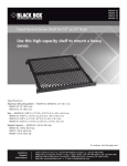
C6AFP70S-24
February
2010
MT1000A-85-R4
C6AFP70S-48
Feed-Through CAT6A Patch Panels
No punchdowns needed with this feed-through panel.
BLACK BOX
®
• Unique staggered panel design features RJ-45 ports on both sides
of the patch panel.
• Feed-through connectors provide easy Category 6A connectivity.
• Perfect for voice and data transmission up to 10 Gbps.
Specifications
Overview
Standards — Category 6A
The Feed-Through CAT6A Patch Panels meet Category 6A
channel performance requirements and provide patching
without punching down the wires to the ports. These sturdy
panels install in relay racks or communications cabinets.
Connectors — C6AFP70S-24: (24) shielded RJ-45 on front, (24) shielded RJ-45 on back;
C6AFP70S-48: (48) shielded RJ-45 on front,
(48) shielded RJ-45 on back
Size — C6AFP70S-24: 1.75"H (1U) x 19"W x 4.5"D
(4.4 x 48.3 x 11.4 cm);
C6AFP70S-48: 3.5"H (2U) x 19"W x 4.5"D
(8.9 x 48.3 x 11.4 cm)
Weight — C6AFP70S-24: 2.02 lb. (0.918 kg); C6AFP70S-48: 3.89 lb. (1.76 kg)
After ordering a CAT6A Patch Panel, you should have received
the following items:
• (1) CAT6A Patch Panel with ground wire installed
• (1) cable management bar for C6AFP70S-24,
or (2) cable management bars for C6AFP70S-48
• (4) 10-32 cuphead screws
• (4) 12-24 cuphead screws
• This users’ manual
If anything is missing or damaged, please contact Black Box at
724-746-5500.
For installation instructions, turn this page over…
Customer
Support
Information
Order toll-free in the U.S.: Call 877-877-BBOX (outside U.S. call 724-746-5500)
FREE technical support 24 hours a day, 7 days a week: Call 724-746-5500 or fax 724-746-0746
Mailing address: Black Box Corporation, 1000 Park Drive, Lawrence, PA 15055-1018
Web site: www.blackbox.com • E-mail: [email protected]
Installation
Use the Feed-Through CAT6A Patch Panels with or without the cable management bar. The bar neatly organizes and supports the
cables that are installed in the rear of the patch panel.
Find an empty rack space on a relay rack or communications cabinet.
Without using the cable management bar:
1. Install the panel with the supplied 10-32 or 12-24 cuphead screws.
2. Install the RJ-45 patch cables on the front and rear connectors to make the connections.
3. Secure the ground wire to a relay rack or cabinet.
Using the cable management bar:
1. Remove the two cuphead screws from the rear of the patch panel.
2. Position the cable management bar on the patch panel and reinstall the two cuphead screws.
3. Install a patch cable in one of the panel’s rear ports. Unscrew the corresponding silver clip behind the installed port and
position the patch cable under the silver bracket. Tighten the screw.
4. For a 48-port patch panel (C6AFP70S-48), repeat Steps 1 through 3 to install the second cable management bar.
5. Secure the ground wire to a relay rack or cabinet.
Installation is complete.
© Copyright 2013. Black Box Corporation. All rights reserved. Printed in U.S.A. Black Box® and the Double Diamond logo are registered trademarks of BB Technologies, Inc. Any third-party
trademarks appearing in this manual are acknowledged to be the property of their respective owners.
C6AFP70S-24, version 1
FREE, live, 24/7 Tech Support is just 30 seconds away.
724-746-5500 | blackbox.com