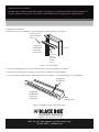
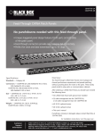
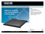
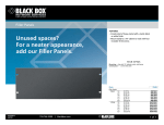
1
July 2010
February
MT1000A-85-R4
JPMT700A
Category 6A Shielded Blank Patch Panel—24-Port
Supports up to 24 Category 6A shielded jacks.
BLACK BOX
®
Mounts in any standard 19" relay rack or cabinet.
Specifications
Number of Ports: 24
Size: 1.75"H (1U) x 19"W x 4.3"D (4.5 x 48.3 x 10.9 cm)
Weight: 2.5 lb. (1.1 kg)
Overview
The Category 6A Shielded Blank Patch Panel (JPMT700A) is used to support up to 24 Category 6A shielded jacks. This panel
mounts in any standard 19" relay rack or cabinet, providing patching connectivity for the Category 6A channel solution. The panel
has a rear plate to provide horizontal cable support and a 9" grounding wire.
NOTE: This product is designed specifically for the Category 6A solution. Other GigaBase®2, GigaTrue®2, or GigaStation2 fittings
may also work in this panel. Contact Black Box Technical Support at 724-746-5500 or [email protected].
What’s Included
Your package should include the following items. If anything is missing or damaged, contact Black Box at 724-746-5500.
• (1) 24-port panel with grounding wire attached
• (4) #12-24 panhead Phillips screws
• (4) #10-32 panhead Phillips screws
• This user’s manual
For assembly instructions, turn this page over…
Customer
Support
Information
Order toll-free in the U.S.: Call 877-877-BBOX (outside U.S. call 724-746-5500)
FREE technical support 24 hours a day, 7 days a week: Call 724-746-5500 or fax 724-746-0746
Mailing address: Black Box Corporation, 1000 Park Drive, Lawrence, PA 15055-1018
Web site: www.blackbox.com • E-mail: [email protected]
Trademarks Used in this Manual
Black Box and the Double Diamond logo, GigaBase2, and GigaTrue2 are registered trademarks of BB Technologies, Inc.
Any other trademarks mentioned in this manual are acknowledged to be the property of the trademark owners.
Assembly Instructions
1. Mount the panels in a standard 19" relay rack using the supplied hardware. See Figure 1.
#12-24 or #10-32
panhead Phillips
screws
Category 6A
Shielded Blank
Patch Panel
(JPMT700A)
19" rack
#12-24 or
#10-32
panhead
Phillips
screws
Figure 1. Panel installation.
2. Connect the grounding wire from the patch panel to the relay rack or cabinet. See Figure 2.
3. Terminate the individual jacks using the instruction sheets supplied with those products.
4. Insert the terminated jacks into the unloaded patch panel. See Figure 2. The locking tab goes in the up position.
Category 6A
Shielded Jack
Category 6A
Shielded Blank
Patch Panel
(JPMT700A)
Grounding wire
Figure 2. Installing the jacks into the patch panel.
©
Copyright 2010. All rights reserved.
FREE, live, 24/7 Tech Support is just 20 seconds away.
724-746-5500 | blackbox.com