1
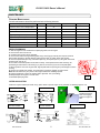
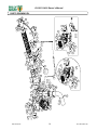
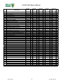
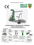
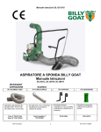
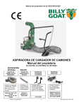
DL12/13/14/18 Owner’s Manual
BILLY GOAT DL TRUCK LOADER VACUUM
Owner's Manual
DL1201L, DL1301H, DL1401SE, DL1801V, DL1801VE
Accessories
INTAKE
HOSE REPLACEMENT KIT
Standard on DL units.
[8"(203mm) x 10' (3.0m)]
[10”(254mm) X 10’(3.0m)]
8” Hose P/N 811244
10” Hose P/N 791033
Part No 812379
EXHAUST
EXHAUST HOSE KIT
[7"(203mm) x 5' (1.5m)] flexible
hose increases exhaust
distance.
7” Flexible Hose P/N 812300
HANGING EXTENSION KIT
EXHAUST EXTENSION KIT
Allows the Debris loader to
hang from a vertical side
panel. (Not for use in
transport)
Allows the height of the
exhaust chute to be raised.
P/N 812260
1
P/N 812273
Form No F060711B
DL12/13/14/18 Owner’s Manual
CONTENTS
SPECIFICATIONS AND SOUND/VIBRATION
3
INSTRUCTION LABELS
4
PACKING CHECKLIST ____________
5
ASSEMBLY AND MOUNTING
6
OPERATION
7
MAINTENANCE________________________________
8
TROUBLE SHOOTING__________________________________________________9
ILLUSTRATED PARTS & PARTS LISTS
10-12
Go to http://www.billygoat.com for French-Canadian translations of the product manuals.
Visitez http://www.billygoat.com pour la version canadienne-française des manuels de produits
Part No 812379
2
Form No F060711B
DL12/13/14/18 Owner’s Manual
Specifications
DL1201L
Engine: HP
DL1301H
DL1401SE
DL1801V
DL1801VE
12 (8.95 kW)
13 (9.69 kW)
14 (9.69 kW)
Engine: Model
HK291150124P-BPQE2
GX390U1QA2
EX400DE5030
3564420186EI
3564470288B1
Engine: Type
LCT OHV
HONDA
SUBARU
BRIGGS AND STRATTON
BRIGGS AND STRATTON
6 qt. (5.68 L)
6.9 qt. (6.5 L)
7.4 qt. (7.0 L)
9qt. (8.52 L)
9qt. (8.52 L)
Engine: Fuel Capacity
18 (13.4 kW)
18 (13.4 kW)
Engine: Oil Capacity
0.875 qt. (0.8 L)
1.16 qt. (1.1 L)
1.3 qt. (1.2 L)
1.75 qt. (1.66 L)
1.75 qt. (1.66 L)
Total Unit Weight:
204 lbs (92.5 kg)
207 lbs (93.9 kg)
267 lbs (93.9 kg)
267 lbs (121.1 kg)
267 lbs (121.1 kg)
250
250
250
250
250
74 7/8” (1.90m)
74 7/8” (1.90m)
74 7/8” (1.90m)
74 7/8” (1.90m)
74 7/8” (1.90m)
91”(2.31m)
91”(2.31m)
91”(2.31m)
91”(2.31m)
91”(2.31m)
Overall Width
32 ¼” (0.82m)
32 ¼” (0.82m)
32 ¼” (0.82m)
32 ¼” (0.82m)
32 ¼” (0.82m)
Overall Length
60” (1.52m)
60” (1.52m)
60” (1.52m)
60” (1.52m)
60” (1.52m)
In compliance with
2000/14/EEC standards
121 dB(a)
121 dB(a)
121 dB(a)
121 dB(a)
121 dB(a)
Sound at operators
position
105 dB(a)
105 dB(a)
105 dB(a)
105 dB(a)
105 dB(a)
Vibration at operator
position
0.02g
0.02g
0.02g
0.02g
0.02g
Max operating slope
Overall Height
Overall Height with
optional trailer
Battery (Electric Models Only)
Model
CCA @ 0° F
DL14
ETX12
180
DL18
U1 Group
275
Battery not
included with
machine
AH Rating
10
19
Length
5.9” (150mm)
6 7/8” (175mm)
Width
3.4” (86mm)
4” (100mm)
Height
5.2” (132mm)
6 1/8” (155mm)
SOUND
SOUND LEVEL 105 dB(a) at Operator Position
Sound tests were conducted in accordance with 2000/14/EEC, and were performed on 6/18/07 under the conditions listed below.
Sound power level listed is the highest value for any model covered in this manual. Please refer to serial plate on the unit for the sound
power level for your model.
General Conditions:
Temperature:
Wind Speed:
Wind Direction:
Humidity:
Barometric Pressure:
Cloudy
o
o
74 F (23.2 C)
3.7 mph (21.6 kmh)
South
83.5%
29.8 Hg (756 mm Hg)
VIBRATION DATA
VIBRATION LEVEL 0.02g
Vibration levels at the operator’s handles were measured in the vertical, lateral and longitudinal directions using calibrated vibration test
equipment. Tests were performed on 7-10-07 under the conditions listed below.
General Conditions:
Temperature:
Wind Speed:
Wind Direction:
Humidity:
Barometric Pressure:
Part No 812379
Sunny
o
o
86 F (17 C)
13 mph (20 kph)
North
49%
29.8”Hg (756mm Hg)
3
Form No F060711B
DL12/13/14/18 Owner’s Manual
INSTRUCTION LABELS
®
The labels shown below were installed on your BILLY GOAT DL Vacuum. If any labels are damaged or missing, replace them before operating
this equipment. Item numbers from the Illustrated Parts List and part numbers are provided for convenience in ordering replacement labels. The
correct position for each label may be determined by referring to the Figure and Item numbers shown.
DANGER KEEP HANDS
AND FEET AWAY
ITEM #18 P/N 400424
EAR EYE BREATHING
ITEM# 31 P/N 890254
READ OWNERS MANUAL
ITEM #30 P/N 830301
WARNING SECURE
ITEM#62 P/N 790232
EXPLOSIVE FUEL
ITEM #32 P/N 400268
WARNING ENGINE OVERHEAT
ITEM #14 P/N 811215
DANGER FLYING DEBRIS
ITEM #61 P/N 810736
LABEL SPARK ARRESTOR
ITEM #15 P/N 100252
SECURE NOZZLE
ITEM #59 P/N 790232
DL INSTRUCT/WARN
ITEM #28 P/N 790142
ENGINE LABELS
HONDA
B&S VANGUARD
OIL ALERT
WHEN OIL LEVELLOW,
ENGINE STOPS IMMEDIATELY.
READ OWNER’S MANUAL BEFORE OPERATION.
LIRE LE MANUEL D UTILISATEUR AVANT USAGE.
VOR INBETRIEBNAHME UNBEDINGHT BEDIENUNGSANLEITUNG DURCHLESEN.
NO UTILIZAR SINANTES NO HABER LEIDO EL MANUAL
HONDA MOTOR CO. , LTD. MADE IN JAPAN
Part No 812379
4
Form No F060711B
DL12/13/14/18 Owner’s Manual
PACKING CHECKLIST
Your Billy Goat is shipped from the factory in one carton and is completely assembled except for the exhaust elbow,
nozzle, handle loop for nozzle, hose booms, hose bands, hose coupler, hose clamps and related hardware.
READ all safety instructions before assembling unit.
TAKE CAUTION when removing the unit from the box.
PUT OIL IN ENGINE BEFORE STARTING
PARTS BAG &
LITERATURE ASSY
Warranty card P/N- 400972, Owner’s Manual P/N-812379, General Safety and Warnings Manual P/N100294, Declaration of Conformity P/N-791090.
Boxing Parts Checklist
Exhaust Elbow PN# 812248-S qty 1
Hose Boom Assembly PN# 812245 qty 1
Boom Chain PN# 791117
Hose quick clamp 8” PN# 812254 qty 1
or Hose quick clamp 10” PN# 791064 qty 1
Band hose boom 8" PN# 810880 qty 1
or Band hose boom 10” PN# 810868 qty 1
Hose 8"x 10' DL PN# 811244 qty 1
or Hose 10”x 10’ DL PN# 791033 qty 1
Handle Nozzle PN# 791116 qty 1
Hose clamps 8" PN# 810566 Qty. 1
or Hose clamps 10” PN# 810706-01 qty 1
Nozzle DL 8” PN# 811007 qty 1
or Nozzle DL 10” PN#811005 qty 1
Engine
LCT 12 HP
Honda 13 HP
Vanguard 18 HP
Vanguard Electric 18 HP
Parts Bag & Literature Assy P/N 812252
56
Washer 5/16 Fender
8172020 qty. 4
Washer 5/16 SAE
8172008 qty. 2
57
53
Nut Lock 1/4-20
8160001 qty. 1
Parts Bag
Hardware
Nut Lock 5/16-18
8160002 qty. 2
52
43
Screwcap 1/4-20 X 2 3/4"
ZP 8041013 qty. 1
54
60
Washer 1/4 SAE
8172007 qty. 2
Part No 812379
Screwcap 5/16-18 X 2"
ZP 8041032 qty. 2
5
Form No F060711B
DL12/13/14/18 Owner’s Manual
ASSEMBLY
1. SECURELY ATTACH unit to the bed of a truck, trailer, or use the hanging brackets, so that the exhaust discharges into an
enclosed container.
NOTE: This unit must be securely mounted to the bed of a truck or to a trailer before operating.
See page 14 for parts diagram to assemble
2. ATTACH hose to housing intake, using hose quick clamp (item 8) making sure to place the safety switch under the clamp (see
interlock page 12. Then slide the hose onto the housing intake and place the shut off switch under the clamp. Make sure the shut off
switch is pressed in or the vacuum will not start, and clamp the hose to the intake.
3. ASSEMBLE nozzle handle (item 11), to nozzle (item 10), using screws (item 60), fender washers (item 56), washers (item 57)
and lock nuts (item 43).
4. ATTACH assembled nozzle to hose using hose clamp (item 9). Before tightening hose clamp, position nozzle handle upward
when hose is stretched to prevent twisting load on hose assembly during operation.
5. ATTACH the hose boom (item 5) by sliding the boom through the ring on the top of housing and resting it in the cup on the top of
the housing.
6. ASSEMBLE hose band (item 13) around hose and secure chain between flanges of the hose band using capscrew (item 52),
washers (item 54), and lock nut (item 53). To adjust the hose boom height see page 11)
7. SECURELY ATTACH exhaust elbow (item 4) to the housing (see MOUNTING on page 10) with the hardware located on the
exhaust chute.
8. INSTALL BATTERY (Electric Models Only)
Due to the location of the battery it is recommended that only the specified
battery be used on the DL1401SE and DL1801VE. This is due to the heat generated by the muffler and the location of the battery.
Using the wrong size battery could result in premature failure, damage to unit or personal injury. The battery needs to be within the
specification list on page 3. The U1 group or equivalent is recommended for the DL18VE (SEE PAGE 3 FOR BATTERY
SPECIFICATIONS)
9. (Electric Models Only) Attach the battery cables to the battery and secure it to the unit with the hold down strap.
MOUNTING
Typical on
both sides
MOUNTING: Main unit
GENERAL: Unit must be securely mounted to a trailer, truck bed,
hanging brackets, or other similar surface before use. Do not use this unit
in a freestanding position. Unit is not stable until it has been secured in
place.
Secure unit by bolting through the base of the unit and through the
mounting surface using 3/8" dia. bolts, with washers and locking nuts
(see fig. 1)
MOUNTING: Exhaust elbow
Note: this process is easier with two people, one to support the exhaust
elbow and one to attach plates and hardware.
1) Remove the bolts (item 50), washers (item 51), and nuts (item 41) from
the parts bag.
2) Place the elbow on top of the housing chute and line up with the holes
in the elbow with the housing in the desired position you want the exhaust
to go.
3) Secure the elbow to the housing with the hardware provided. Make
sure the hardware is properly tightened.
Part No 812379
6
Fig. 1
Mount with
these holes
on both sides
Step 1&2
Form No F060711B
DL12/13/14/18 Owner’s Manual
VACUUMING OPERATION
EXHAUST DIRECTION & DISTANCE: Exhaust direction and distance are controlled by
the rotation of the exhaust elbow. Typically debris is aimed to discharge to the rear of the
container. The direction of discharge is adjusted by rotating the exhaust elbow on the
housing and securing with the hardware provided.
NOTE: Elbow is heavy. Use caution when adjusting. Never stand directly under the elbow
while adjusting direction of exhaust.
Never direct exhaust into an area where bystanders may cross the path of the
debris.
INTAKE OPERATION: With machine running and fully assembled, move the nozzle in
sweeping motions over debris. Always allow air to flow into the nozzle along with the
debris. Do not completely block the nozzle when vacuuming, it will reduce performance,
and increase clogging (See figure 3).
For removal of heavier debris, or debris that is stuck to the ground, rock nozzle forward to
concentrate suction power around the debris (See figure 4).
Fig. 3
ADJUSTING HOSE BOOM
Properly adjusting the boom will prevent most hose clogs from occurring and will
maximize vacuum performance by keeping the hose straight and perpendicular
to the housing (see fig. 5). Height adjustments are made by raising or lowering
one of the attachment links to a different area on the chain.
UNCLOGGING A CLOGGED HOSE
With engine running and unit secured to a trailer, truck bed, or other similar surface,
fully stretch hose in a straight line to dislodge the clog. If the clog will not clear, turn unit
off, and allow engine to come to a complete stop. Remove hose and manually clear
hose clog. NOTE: The clogged debris may be sharp. Always wear durable gloves when
removing clog.
UNCLOGGING A CLOGGED HOUSING OR EXHAUST ELBOW
Turn engine off and wait for impeller to come to a complete stop. Disconnect spark plug
wires and battery cables. Remove the hose from the housing and determine where the
clog is located. If possible clear the clog through the intake opening. It may require
removal of the intake adaptor (item 16) to allow access to clear the housing. If clog is in
the elbow, carefully remove the elbow. Remove elbow by removing the bolts and nuts
on the elbow clamp so that the plates can be removed.
NOTE: Elbow is very heavy. Do not stand directly under elbow during removal.
Danger, the clog may contain sharp materials. Wearing durable gloves, clear the clog.
Reconnect spark plug wire.
Fig. 4
Fig. 5
HOSE CARE AND TIPS
To increase hose life, periodically rotate hose and reposition nozzle and coupler on
front plate of unit. This increases hose life by keeping hose from wearing only on one
side.
Keep hose as straight as possible and avoid sharp bends during operation for best pickup and to avoid clogs.
Never drag hose. Always remove and store hose before transporting unit.
Store hose straight and flat to maintain flexibility for next use.
THE HOSE IS A REPLACEABLE WEAR ITEM.
Hose
Hose Band.
Stretch hose out
before clamping
.
HOSE STORAGE: Storing hose in a covered area, out of sunlight and heat will prolong hose life. Do not store hose where it could
be stepped on or where other objects could crush or damage hose.
Part No 812379
7
Form No F060711B
DL12/13/14/18 Owner’s Manual
MAINTENANCE
PERIODIC MAINTENANCE
Periodic maintenance should be performed at the following intervals:
Maintenance Operation
Every use
Every 5 hours (daily)
Every 10 Hours
Every 25 Hours
z
Inspect for loose, worn or damaged parts.
Check engine oil and air filter
z
Clean hose
z
Engine (See Engine Manual)
z
Inspect battery for damage or leak
z
Keep engine free of debris
z
Check battery terminal for corrosion
z
Check for excessive vibration
IMPELLER REMOVAL
1. Wait for engine to cool and disconnect spark plug wires from the engine.
2. Remove the hose from the unit.
3. Unattach the hose from boom assembly.
4. Remove the intake housing assembly (item 16) by removing (6) locknuts (item 44). Be careful to
place intake assembly to the side without putting excess strain on safety switch wire harness
5. Remove impeller bolt (item 34), lock washer (item 35), and spacer (item 37) using 5/8" socket and
impact wrench (see fig. 6).
6. Once bolt is removed impeller should slide out freely. If the impeller doesn’t slide off freely use
penetrating oil and work the hub off using a pry bar. Do not use the pry bar on the impeller plate.
7. When impeller is free of the engine shaft, align impeller with the opening and pull it straight out of the
housing.
8. Using a new impeller bolt, washer, and lock washer, install new impeller in reverse order.
Note: Be sure that the key is in place on the engine shaft before installing impeller.
9. Tighten impeller bolt. Torque the impeller bolt to [33-38 Ft. Lbs. (45-52 N.m)]
10. Repeat steps 2 through 5 in reverse order.
11. Reinstall spark plug wires.
Fig. 6
INTERLOCK SYSTEM
With hose coupler installed (as shown in Fig. 8) the switch is open & engine is not grounded out, allowing engine to run.
DL1801V SYSTEM
I G N IT IO N
U N IT
IG N IT IO N
U N IT
S p a r k p lu g
IN T E R L O C K
S W IT C H
E N G IN E
S W IT C H
S p a r k p lu g
DL1301H SYSTEM
Spark plug
IGNITION
UNIT
INTERLOCK
SWITCH
ENGINE
SWITCH
IGNITION
UNIT
Hose must be
installed and switch
lever must engage
switch for engine to
start.
Spark plug
DL1401SE SYSTEM
DL1201L SYSTEM
IGNITION
UNIT
Throttle
stop
Spark plug
INTERLOCK
SWITCH
Part No 812379
Fig. 8
DL1801VE SYSTEM
8
ENGINE
SWITCH
Form No F060711B
DL12/13/14/18 Owner’s Manual
Troubleshooting
Problem
Abnormal vibration.
Engine will not start.
Possible Cause
Loose or out of balance impeller or
loose engine
· Nozzle buried in debris. Clogged
hose or exhaust. Excessive quantity of
debris.
· Throttle & / or stop switch in off
position. Out of gasoline. Bad or old
gasoline. Spark plug wire
disconnected. Harness wire is bad or
disconnected from interlock switch.
Hose not installed, allowing interlock
wire to ground. Dirty air cleaner.
Solution
Check impeller and replace if necessary.
Check engine.
· Withdraw nozzle from debris pile.
Unclog hose or exhaust (see pg. 11)
Allow air to feed debris.
· Check stop switches, throttle, and
gasoline. Connect spark plug wire. Clean
or replace air cleaner. Install hose
coupler securely to the unit and check
whether interlock switch is engaged by
lever. Check harness wire connection
and replace if necessary.
Engine is locked, will not pull
over.
· Debris locked against impeller.
Engine problem.
· See pg.11, Clearing a clogged impeller
housing. Contact an engine servicing
dealer for engine problems.
Will not vacuum or has poor
vacuum performance
Part No 812379
9
Form No F060711B
DL12/13/14/18 Owner’s Manual
PARTS DRAWING DL
56
57
60
43
63
27
9
10
46
59 14
65
36
DL18VE
MODEL
47
12
11
48
53
1
71
46
31
52
18
77
69
43
30
26
6
54
13
68
42
67
70
17
20
21
7
19
8
76
63
21
23
44
27
55
DL18V
MODEL
47
36
33
TO
ENGINE
66
34 35
43
22
46
16
48
1
39
71
46
69
77
68
31
29
45
41 40
24
67
70
50
51
35
ON 28 103
DL18V
MODEL
43
30
26
5
64
49
3
61
28
41
40
25
41 38
46
4
47
2
32
15
1
43
46
62
14
53
80
79
ON
DL14SE
40
AND
DL18VE
MODEL
Form No F060711B
10
Part No 812379
DL12/13/14/18 Owner’s Manual
PARTS LIST
ITEM
NO.
1
2
3
4
5
6
7
8
9
10
11
12
13
14
15
16
17
18
19
20
21
22
23
24
25
26
27
28
29
30
31
32
33
34
35
DESCRIPTION
ENGINE LCT
ENGINE HONDA
ENGINE VANGUARD
ENGINE VANGUARD ELECTRIC
ENGINE SUBARU ELECTRIC
BASE ENGINE WA
HOUSING WA DL12/13 W/LABELS
HOUSING WA DL18 W/LABELS
ELBOW ASSY 7" DL
BOOM WA DL
CHAIN HOSE HANG DL
HOSE 8"X10"
HOSE 10" X 10"
CLAMP QUICK RELEASE 8"
CLAMP QUICK RELEASE 10"
CLAMP HOSE 8"
CLAMP HOSE 10"
NOZZLE 8" STEEL FORMED W/LABELS
NOZZLE 10" STEEL FORMED W/LABELS
HANDLE NOZZLE WA DEBRIS LOADER
GRIP 1 1/4 I.D. X 9.5 LONG
BAND HOSE BOOM 8" FORMED
BAND HOSE BOOM 10" FORMED
LABEL WARNING ENGINE OVERHEAT
LABEL SPARK ARRESTOR
PLATE FRONT WA DL 8"
PLATE FRONT WA DL 10"
FLAPPER WA 8" W/LABELS
FLAPPER WA 10" W/LABELS
LABEL WARNING OPEI
STRAIN RELIEF HEYCO 1244
LEVER HOSE SWITCH
SWITCH AND HARNESS DL ASSY
CONNECTOR TAP IN SQUEEZE
SPACER 3/8" X 2 1/2"
LINER DL12/13
LINER DL18
PLATE ENGINE MOUNT DL12/13
PLATE ENGINE MOUNT DL18
GUARD MUFFLER DL18
GUARD MANIFOLD DL18
LABEL DL INSTRUCTION/WARNING
LABEL LOGO DL12/13/18
SPACER CONTROL LIFT
SCREW SN #10 X 1" TYPE A SLOT HWH
LABEL WARNING FUEL EN/SP
IMPELLER ASSY
IMPELLER ASSY
SCREWCAP 3/8"-24 X 2 3/4" GR 8. W/PATCH
SCREWCAP 3/8"-24 X 2 1/4" GR 8.
SCREWCAP 3/8"-24 X 2" GR 8. W/PATCH
TORQUE 33-38 FT LBS. (45-52 N.m)
WASHER LOCK 3/8"
Part No 812379
DL1201L
DL1301H
DL1401SE
DL1801V
DL1801VE
QTY
QTY
QTY
QTY
QTY
PART
PART
PART
PART
PART
NO.
NO.
NO.
NO.
NO.
811250
1
430366
1
812240
1
812241
1
812369
1
812100-S
1
812100-S
1
812100-S
1
812100-S
1
812100-S
1
812216-S
1
812216-S
1
812101-S
1
812101-S
1
812101-S
1
812248-S
1
812248-S
1
812248-S
1
812248-S
1
812248-S
1
812245
1
812245
1
812245
1
812245
1
812245
1
791117
1
791117
1
791117
1
791117
1
791117
1
811244
1
811244
1
791033
1
791033
1
791033
1
812254
1
812254
1
791064
1
791064
1
791064
1
810566
1
810566
1
- 810706-01 1 810706-01 1
810706-01
1
811007-S
1
811007-S
1
811005-S
1
811005-S
1
811005-S
1
791116
1
791116
1
791116
1
791116
1
791116
1
440146
2
440146
2
440146
2
440146
2
440146
2
810880
1
810880
1
810868
1
810868
1
810868
1
811215
2
811215
2
811215
2
811215
2
811215
2
100252
1
100252
1
100252
1
100252
1
100252
1
812104-S
1
812104-S
1
812103-S
1
812103-S
1
812103-S
1
812230-S
1
812230-S
1
791102-S
1
791102-S
1
791102-S
1
400424
1
400424
1
400424
1
400424
1
400424
1
500282
1
500282
1
500282
1
500282
1
500282
1
791068
1
791068
1
791068
1
791068
1
791068
1
791130
1
791130
1
791130
1
791130
1
791130
1
810673
1
810673
1
810673
1
900503
1
900503
1
900503
1
900503
1
900503
1
812221
1
812221
1
812214
1
812214
1
812214
1
812235
1
812235
1
812238
1
812238
1
812238
1
812242
1
812242
1
812243
1
812243
1
790142
1
790142
1
790142
1
790142
1
790142
1
812213
1
812213
1
812213
1
812213
1
812213
1
850198
4
850198
4
8122066
4
8122066
4
100261
1
100261
1
100261
1
812257-S
1
812257-S
1
810930
1
810930
1
810930
1
790167
1
790167
1
810932
1
810932
1
440237
1
8177012
5
11
8177012
5
8177012
5
8177012
5
8177012
Form No F060711B
5
DL12/13/14/18 Owner’s Manual
SCREWCAP 5/16-18 X 2" HCS ZP
DL1201L
PART
NO.
-
KEY 1/4 SQ X 2 3/4"
BOLT CARRIAGE 3/8 -16 X 1" ZP
WASHER 3/8 FLAT CUT
NUT LOCK 3/8-16 HEX ZP
BOLT CARRIAGE 5/16" - 18 X 3 1/2" ZP
NUT LOCK 5/16-18 HEX ZP
NUT FLANGE 5/16-18 HEX ZP
SCREWCAP 3/8-16 X 3" HCS ZP
SCREWCAP 3/8-16 X 1 3/4" HCS ZP
WASHER 5/16 FLAT ZP
SCREWCAP 5/16-18 X 1 3/4" HCS ZP
SCREW SM 1/4 X 3/4" TYPE AB HX WF
HEX WASHER FACE BOLT 3/8-16 X 3/4
SCREWCAP 3/8-16 X 1" HCS ZP
WASHER 3/8 SAE
SCREWCAP 1/4"-20 X 2 3/4" HCS ZP
NUT LOCK 1/4-20 HEX ZP
NUT LOCK 3/8"-16 HEX (DL14 BATTERY BRACKET)
WASHER 1/4-20 HEX ZP
CLAMP HOSE FUEL LINE
WASHER FENDER 5/16
WASHER 5/16 SAE
LABEL SECURE NOZZLE
SCREWCAP 5/16" - 18 X 2"
LABEL FLYING DEBRIS
WARNING SECURE
SCREW SM 1/4 X 1" DRILL PT.
SPACER 1" ID X 2" OD X 0.265 THK
SPACER 1" ID X 2" OD X 0.890 THK
PLUG TUBE INSERT 1.25 OD
DEBRIS REDUCER DL12/13/18
THROTTLE CONTROL BLOWER
BRACKET MOUNT THROTTLE CONTROL
CABLE THROTTLE DL18
SCREW MACH FLAT HD PHIL #10-24
NUT LOCK #10-24 HEX
CABLE BATTERY RED 36"
CABLE BATTERY BLACK 20"
ITEM
NO.
36
37
38
39
40
41
42
43
44
45
46
47
48
49
50
51
52
53
54
55
56
57
58
59
60
61
62
63
64
65
66
67
68
69
70
71
72
73
74
75
76
77
78
79
80
103
DESCRIPTION
BATTERY 12 V (NOT SUPPLIED, SEE PAGE 3
FOR BATTERY MODEL AND SPECIFICATIONS)
PIN SAFETY
WASHER LOCK 1/4" EXTERNAL TOOTH
TERMINAL PIGGY BACK 3/16"
BRACKET BATTERY DL
SCREWCAP 1/4"-20 X 1 1/4" HCS ZP
BOLT CARRIAGE 3/8-16 X 1" ZP
LABEL MADE IN U.S.A.
Part No 812379
-
DL1301H
DL1401SE
DL1801V
QTY
QTY
PART
PART
PART
NO.
NO.
NO.
8041032
9201125
8024058
8171004
8160003
8024050
8160002
350346
8041058
8171003
8041031
791080
8041050
8172009
8041013
8160001
8172007
791070
8172020
8172008
1
4
4
8
1
7
6
4
8
4
3
4
8
1
1
2
2
4
2
9201125
8024058
8171004
8160003
8024050
8160002
350346
8041058
8171003
8041031
791080
8041050
8172009
8041013
8160001
8172007
791070
8172020
8172008
1
4
4
8
1
7
6
4
8
4
3
4
8
1
1
2
2
4
2
9201125
8024058
8171004
8160003
8024050
8160002
350346
8041053
8171003
8041031
791080
8041050
8172009
8041013
8160001
8160003
8172007
791070
8172020
8172008
1
4
6
8
1
7
6
4
8
4
3
4
8
1
1
2
2
2
4
2
9201125
8024058
8171004
8160003
8024050
8160002
350346
8041053
8171003
8041031
890359
791080
8041050
8172009
8041013
8160001
8172007
791070
8172020
8172008
1
4
4
8
1
7
10
4
8
2
2
3
4
8
1
1
2
2
4
2
9201125
8024058
8171004
8160003
8024050
8160002
350346
8041053
8171003
8041031
890359
791080
8041050
8172009
8041013
8160001
8172007
791070
8172020
8172008
1
4
4
8
1
7
10
4
8
2
2
3
4
8
1
3
2
2
4
2
790301
8041032
810736
790232
830113
791056
812283
-
1
2
2
1
2
2
1
-
790301
8041032
810736
790232
830113
791056
812283
-
1
2
2
1
2
2
1
-
790301
8041032
810736
790232
830112
791056
812283
812282
812341
1
2
2
1
1
2
1
1
1
790301
8041032
810736
790232
430208
791056
812283
440013
812280
812281
830514
8164005
-
1
2
2
1
2
2
1
1
1
1
2
2
-
790301
8041032
810736
790232
430208
791056
812283
440013
812280
812281
830514
8164005
812282
812341
1
2
2
1
2
2
1
1
1
1
2
2
1
1
-
-
-
-
REF
REF
-
-
REF
REF
800365
520116
1
1
800365
520116
1
1
800365
8024058
520116
1
2
1
800365
8181007
520116
1
4
1
800365
8181007
890010
812340
8041008
520116
1
4
1
1
2
1
QTY
12
QTY
2
DL1801VE
QTY
PART
NO.
8041032
2
Form No F060711B