1
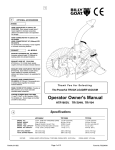
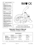
HTR/TR Owner’s Manual
BILLY GOAT TRUCK LOADER VACUUM
Owner's Manual
HTR1803V, TR1304H, TR1204L
Accessories
INTAKE
HOSE COUPLER
KIT 8" (203mm)
TR
Quick release
coupler joins 2
hoses together to
increase
vacuuming
distance and
allows hoses to be
separated for
storage.
P/N 810525
HOSE
CONNECTOR KIT
8" (203mm) TR &
10" (254mm) HTR
For permanently
connecting 2 hoses
together to
increase
vacuuming
distance.
P/N 810524 &
810776
Part No 811202
EXHAUST
EXHAUST
EXTENSION
KIT
Increases
exhaust
height
11"(280mm)
for loading
debris into
elevated
locations.
P/N 810637
EXHAUST
HOSE KIT
EXHAUST
HOSE
COUPLER KIT
[6"(152mm) x
10' (3.0m)]
Quick release
coupler and
hose
increases
exhaust
distance.
Quick release
coupler joins 2
hoses together
to increase
exhaust
distance and
allows hoses to
be separated for
storage.
[6"(152mm)]
Permanently
joins 2 exhaust
hoses together
to increase
exhaust
distance.
Provides
air filter
panel for
use on
truck and
trailer
mounted
debris
enclosures.
1.3 yds.3
(1.0m3) or
28.4 bushels
(1000L). For
portable use.
Several bags
can be filled
and left for
later pickup.
P/N 811206
P/N 811207
P/N 800336
P/N 810584
P/N 810660
1
EXHAUST
HOSE
CONNECT0R
KIT
PANEL
FILTER
KIT
PORTABLE
DEBRIS BAG
Form No F071408A
HTR/TR Owner’s Manual
ABOUT THIS MANUAL
THANK YOU for purchasing a BILLY GOAT ® TR/HTR Vacuum. Your new machine has been carefully designed
and manufactured to provide years of reliable and productive service. This manual provides complete operating and
maintenance instructions that will help to maintain your machine in top running order. Read this manual carefully
before assembling, operating, or servicing your equipment.
CONTENTS
SERIAL PLATE DATA AND SPECIFICATIONS
3
4-5
GENERAL SAFETY
SOUND AND VIBRATION
6
INSTRUCTION LABELS
7
PACKING CHECKLIST & ASSEMBLY
8-9
OPERATION
9-10
MAINTENANCE
11
TROUBLESHOOTING AND WARRANTY PROCEDURE
12
MAINTENANCE RECORD
13
ILLUSTRATED PARTS & PARTS LISTS
Part No 811202
14-16
2
Form No F071408A
HTR/TR Owner’s Manual
SERIAL PLATE DATA
Record the model number, serial number, date of
purchase, and where purchased.
Purchase Date:
Purchased From:
Specifications
HTR1803V
TR1304H
18 (13.4 kW)
13 (9.69 kW)
12 (8.95 kW)
Engine: Model
3564420186EI
GX390U1QA2
HK291150124P-BPQE2
Engine: Type
BRIGGS & STRATTON
HONDA
LCT OHV
9qt. (8.52 L)
6.9 qt. (6.0 L)
4.0 qt (3.8 L)
Engine: Oil Capacity
1.75 qt. (1.66 L)
1.16 qt. (1.1 L)
0.875 qt. (0.8 L)
Total Unit Weight:
274# (124.3 kg)
240# (108.0 kg)
237# (107.5 kg)
Engine: HP
Engine: Fuel Capacity
Max operating slope
20
0
20
0
TR1204L
20
0
Sound in accordance with
2000/14/EEC standards
121 dB(a)
121 dB(a)
121 dB(a)
Sound at operators ear
105 dB(a)
105 dB(a)
105 dB(a)
0.02g
0.02g
0.02g
Vibration at operator position
Part No 811202
3
Form No F071408A
HTR/TR Owner’s Manual
GENERAL SAFETY INSTRUCTIONS and SYMBOLS
The safety symbols shown below are used throughout this manual. You should become familiar with them before
assembling, operating, or servicing this equipment.
This symbol indicates important information that will prevent injury to yourself or others.
This symbol indicates ear protection is recommended when operating this equipment.
This symbol indicates eye protection is recommended when operating this equipment.
This symbol indicates gloves should be worn when servicing this equipment.
This symbol indicates that this manual and the engine manufacturer’s manual should be read
carefully before assembling, operation, or servicing this equipment.
This symbol indicates important information that will prevent damage to your BILLY GOAT
HTR/TR VACUUM.
®
This symbol indicates the engine oil level should be checked before operating this
equipment.
Read and make sure you thoroughly understand the following safety precautions before assembling, operating or
servicing this equipment:
READ this manual and the engine manufacturer’s manual carefully before assembling,
operating, or servicing this equipment.
EAR PROTECTION is recommended when operating this equipment.
EYE PROTECTION is recommended when operating this equipment.
BREATHING PROTECTION is recommended when operating this equipment.
EXHAUST from this product contains chemicals known to the State of California to cause
cancer, birth defects or other reproductive harm.
DO NOT operate this equipment on any unimproved forested, brushy, or grass covered land
unless a spark arrester is installed on the muffler as required by Section 4442 of the
California Public Resources Code. The arrester must be maintained in good working order.
Other states may have similar laws. Federal laws apply on federal lands.
DO NOT run engine in an enclosed area. Exhaust gases contain carbon monoxide, an
odorless and possibly fatal poison.
Part No 811202
4
Form No F071408A
HTR/TR Owner’s Manual
DO NOT run this equipment indoors or in any poorly ventilated area. Refueling outdoors is recommended.
DO NOT refuel this equipment while the engine is running. Allow engine to cool for at least two minutes before
refueling.
DO NOT store gasoline near an open flame.
DO NOT remove gas cap while engine is running.
DO NOT start or operate engine if strong odor of gasoline is present.
DO NOT start or operate engine if gasoline is spilled. Move equipment away from spill until gasoline has
completely evaporated.
DO NOT smoke while filling the fuel tank.
DO NOT check for spark with spark plug or spark plug wire removed. Use an approved spark tester.
DO NOT operate engine without a muffler. Inspect muffler periodically and replace if necessary. If equipped with
muffler deflector, inspect deflector periodically and replace if necessary.
DO NOT operate engine with grass, leaves or other combustible material near the muffler.
DO NOT touch muffler, cylinder, or cooling fins when hot. Contact with hot surfaces may cause severe burns.
DO NOT leave equipment unattended while in operation.
DO NOT operate equipment with bystanders in or near the work area.
DO NOT allow children to operate this equipment.
DO NOT operate equipment with guards removed.
DO NOT operate equipment near or pick up hot or burning debris or any toxic or explosive materials.
DO NOT operate equipment on slopes greater than specified in Specifications section of this manual.
DO NOT start engine without height adjust lever in up position and clutch bail disengaged.
DO NOT place hands or feet inside nozzle intake, near debris outlet, or near any moving parts.
WARNING: Important
DO NOT use this machine for vacuuming exclusively sand, dust, fine dirt, rock, glass, string like material, grain, rags,
cans, metal, bark or water.
DO NOT start engine without hose and exhaust elbow connected firmly in place to housing and outlet.
DO NOT operate without discharging exhaust into enclosed container.
DO NOT operate with hose or exhaust elbow removed
DO NOT remove hose until engine has been turned off and has come to a complete stop.
ALWAYS remove spark plug wire when servicing equipment to prevent accidental starting.
ALWAYS check fuel lines and fittings frequently for cracks or leaks. Replace if necessary.
ALWAYS keep hands and feet away from moving or rotating parts.
ALWAYS store fuel in approved safety containers.
Part No 811202
5
Form No F071408A
HTR/TR Owner’s Manual
SOUND
SOUND LEVEL 105 dB(a) at Operator Position
Sound tests were conducted in accordance with 2000/14/EEC, and were performed on 5-28-2002 under the
conditions listed below.
Sound power level listed is the highest value for any model covered in this manual. Please refer to serial plate on
the unit for the sound power level for your model.
General Conditions:
Temperature:
Wind Speed:
Wind Direction:
Humidity:
Barometric Pressure:
Sunny
45oF (7.2oC)
5 mph (8.1 kmh)
South West
60%
30.18Hg (767 mm Hg)
VIBRATION DATA
VIBRATION LEVEL 0.02g
Vibration levels at the operator’s handles were measured in the vertical, lateral and longitudinal directions using
calibrated vibration test equipment. Tests were performed on 7-14-94 under the conditions listed below.
General Conditions:
Temperature:
Wind Speed:
Wind Direction:
Humidity:
Barometric Pressure:
Sunny
78oF (23.8oC)
16 mph (25.7kmh)
South East
62%
30.1”Hg (765mm Hg)
INTENDED USE
INTENDED USE: This machine is designed for vacuuming leaves, grass clippings and other types of organic litter.
Debris mixed with cans, bottles and small amounts of sand can be vacuumed; however, it is not this machine's
primary purpose. Vacuuming cans, bottles and sand will affect the longevity of your machine.
Do not operate if excessive vibration occurs. If excessive vibration occurs, shut engine off immediately and check
for damaged or worn impeller, loose impeller bolt, loose impeller key, loose engine or lodged foreign objects. Note:
For proper impeller bolt torque specifications. (See impeller removal section on page 11).
Part No 811202
6
Form No F071408A
HTR/TR Owner’s Manual
INSTRUCTION LABELS
®
The labels shown below were installed on your BILLY GOAT TR/HTR Vacuum. If any labels are damaged or missing, replace them before
operating this equipment. Item numbers from the Illustrated Parts List and part numbers are provided for convenience in ordering replacement
labels. The correct position for each label may be determined by referring to the Figure and Item numbers shown.
LABEL DANGER KEEP HANDS
AND FEET AWAY
ITEM #3 P/N 400424
LABEL EAR EYE BREATHING
ITEM# 48 P/N 830503
LABEL READ OWNERS MANUAL
ITEM #15 P/N 830301
LABELENGINEOVERHEAT
ITEM#49 P/N 811215
LABEL EXPLOSIVE FUEL
ITEM # 81 P/N 400268
DANGER FLYING DEBRIS
ITEM #19 P/N 810736
LABEL CAUTION
ITEM #47 P/N 830138
ENGINE LABELS
BRIGGS & STRATTON (VANGUARD)
HONDA
THROTTLE CONTROLS
TR Units have
frame mounted
throttle controls as
shown here.
Engine
Stop
Switch
Briggs Vanguard
Units have an
engine mounted
throttle control.
Start
position
Stop
position
Part No 811202
7
Form No F071408A
HTR/TR Owner’s Manual
PACKING CHECKLIST
Your Billy Goat is shipped from the factory in one carton and is completely assembled except for the exhaust elbow,
nozzle, handle loop for nozzle, hose booms, hose bands, hose coupler, hose clamps and related hardware.
READ all safety instructions before assembling unit.
TAKE CAUTION when removing the unit from the box.
PUT OIL IN ENGINE BEFORE STARTING
PARTS BAG &
LITERATURE ASSY
Warranty card P/N- 400972, Owner’s Manual P/N-811202, Declaration of Conformity P/N-811204,
Literature HTR/TR Accessories 811208.
TR MODELS
Boxing Parts Checklist
Honda 13 HP
LCT 12 HP
Exhaust Elbow 811191
Boom Square Arm 810875
Boom Pivot WA 810870
Band Hose Boom 8" (203mm)
TR 810880 Qty. 2
Band Hose Boom 10" (254mm)
HTR 810868 Qty. 2
Coupler Weld Assy. 8"
(203mm) TR 811170
Coupler Weld Assy. 10"
(254mm) HTR 811179
Hose Clamps 8"(203mm) TR
810566 Qty. 2
Hose Clamps 10" (254mm)
HTR 810706-01 Qty. 2
HTR MODEL
B&S 18 HP
Vanguard- twin
Hose 8”x10’ TR
P/N 811244
Hose 10"x 10'
HTR P/N 791033
Handle Nozzle
791116 TR and HTR
Parts Bag &
Literature Assy
P/N 811128
Parts Bag
Hardware
Nozzle 8"(203mm) TR 811007
Nozzle 10" (254mm) HTR
811005
79
W a sh e r 5 /1 6 F en de r
8 1 7 2 0 2 0 q ty. 4
55
52
N u t L o ck 1 /4 -20
8 1 6 0 00 1 q ty. 4
TR O N LY
S cre w ca p 1 /4 -2 0x 3 "
8 0 4 1 0 1 4 q ty. 2
80
W a she r 5 /16 S A E
8 1 7 2 0 0 8 q ty. 6
N u t Lo c k 5 /16 -1 8
8 16 0 0 0 2 q ty. 2
54
Part No 811202
S cre w ca p 1 /4 -20 x 1 3/4
8 0 4 1 0 0 9 q ty. 2
H TR O NLY
55
5
4
S cre w ca p 5 /1 6-1 8x 1
3 /4 80 4 1 0 3 1 qty. 2
C h a in L o o p A ssy
8 1 0 8 7 8 q ty. 2
8
Form No F071408A
HTR/TR Owner’s Manual
ASSEMBLY
1. ASSEMBLE exhaust elbow (item 10), to main unit and firmly tighten knobs (item 90), that are preassembled to main unit.
2. SECURELY ATTACH unit to tailgate of a truck or to a trailer, so that the exhaust discharges into an enclosed container.
3. ATTACH hose to hose coupler (item 24), using hose clamp (item 60)
4. ASSEMBLE hose coupler to housing of main unit and securely tighten knob (item 13), that is preassembled to housing front plate.
5. ASSEMBLE nozzle handle loop (item 82), to nozzle handle using screw (item 80), washer (item 6) and lock nut (item 5). Adjust
handle loop to desired height and angle and securely tighten in place.
6. ASSEMBLE nozzle handle (item 78), to nozzle (item 77), using screws (item 80), washers (item 79), washers (item 4) and lock
nuts (item 5).
7. ATTACH assembled nozzle to hose using hose clamp (item 60). Before tightening hose clamp, position nozzle handle upward
when hose is stretched to prevent twisting load on hose assembly during operation.
8. ASSEMBLE tube square boom (item 51), to boom pivot (item 50), using chain loop assembly (item 54), washers (item 4) and lock
nut (item 52).
9. ASSEMBLE remaining chain loop assembly (item 54), to end of tube square boom (item 51) using washer (item 4) and lock nut
(item 52).
10. SLIDE boom assembly into square tube on front of housing.
11. ASSEMBLE hose bands (item 56) around hose and onto chain loop assemblies on boom assembly using screws (item 55) and
lock nuts (item 52) (see ADJUSTING HOSE BOOM on page 10).
OPERATION
Like all mechanical tools, reasonable care must be used when operating machine.
Inspect machine work area and machine before operating. Make sure that all operators of this
equipment are trained in general machine use and safety.
PUT OIL IN ENGINE BEFORE STARTING
STARTING
SECURE LOADER TO TAILGATE OR MOUNTING
ENGINE: See engine manufacturer’s instructions for type and amount of oil and gasoline used. Engine must be level when
checking and filling oil and gasoline.
ENGINE SPEED: Controlled by throttle lever on the frame (18HP Twin on engine). Under normal conditions, operate at
minimum throttle to accomplish your current cleaning task.
FUEL VALVE: Move fuel valve to "ON" position (when provided on engine).
INTAKE HOSE: Must be attached to front plate to start engine.
CHOKE: Located on engine near engine throttle panel.
STOP SWITCH: Move to on position (when provided).
THROTTLE: Move remote throttle control to fast position. Pull starting rope to start engine.
IF YOUR UNIT FAILS TO START:
See Troubleshooting on page 12.
HANDLING & TRANSPORTING:
ALWAYS REMOVE LOADER FROM TAILGATE OR MOUNTING BEFORE TRANSPORTING OR OPENING
TAILGATE. Using two people to lift machine is recommended. Lift holding the rear handle and front of frame. Secure in place
during transport. See page 3 for weight specifications.
HOSE: DO NOT drag the hose with vehicle.
Never lift the machine while the engine is running.
Part No 811202
9
Form No F071408A
HTR/TR Owner’s Manual
VACUUMING OPERATION
EXHAUST FLAPPER: Discharging into enclosed container, position exhaust flapper
to desired opening and secure adjustment knob before starting engine. NOTE: An
enclosed container must capture all debris delivered into it preventing any debris from
blowing back onto unit's engine (see page 1 optional accessories).
NOZZLE: With machine running and fully assembled, move nozzle in sweeping
motions over debris. For maximum pickup, move nozzle close to debris, but without
blocking airflow into the nozzle (see figure 1). NOTE: Never bury nozzle into debris.
HOSE OPERATION TIPS
THE HOSE IS A REPLACEABLE WEAR ITEM.
Fig. 1
FOR BEST HOSE OPERATION RESULTS, FOLLOW THESE
RECOMMENDATIONS.
Keep hose as straight as possible during operation for best pick-up and to avoid
clogs.
Avoid sharp bends in hose, which will reduce efficiency and may promote clogs.
NEVER DRAG HOSE. Always remove and store hose before transporting unit.
ADJUSTING HOSE BOOM
Boom Assembly
after hose has
been stretched
Fig. 2
Properly adjusting the boom will prevent most hose clogs from occurring and will
give optimum vacuum performance by keeping hose straight next to housing
(see fig. 2).
UNCLOGGING A CLOGGED HOSE
With engine running and unit secured to tailgate, fully stretch hose in a straight line to
dislodge the clog. If the clog will not clear, turn unit off, and allow engine to come to a
complete stop. Remove hose and manually clear hose clog.
Hose
Hose Bands.
Stretch hose out
before clamping
UNCLOGGING A CLOGGED HOUSING OR EXHAUST ELBOW
Turn engine off and wait for impeller to come to a complete stop. Disconnect spark plug
wire. Danger, the clog may contain sharp materials. Wearing durable gloves, clear the
clog. Reconnect spark plug wire.
HOSE LIFE
To increase hose life, periodically rotate hose and reposition nozzle and coupler on
front plate of unit. This increases hose life by keeping hose from wearing only on one
side.
HEAVY DEBRIS REMOVAL
Fig. 3
TILT NOZZLE FORWARD TO PICK UP DIFFICULT DEBRIS.
STORAGE
Turn fuel supply off when unit is not in use.
Never store engine indoors or in enclosed poorly ventilated areas with fuel in tank, where fuel fumes may reach an
open flame, spark or pilot light, as on a furnace, water heater, clothes dryer or other gas appliance.
If engine is to be unused for 30 days or more, prepare as follows:
Be sure engine is cool. Do not smoke. Remove all gasoline from carburetor and fuel tank to prevent gum deposits
from forming on these parts and causing possible malfunction of engine. Drain fuel outdoors, into an approved
container, away from open flame. Run engine until fuel tank is empty and engine runs out of gasoline.
NOTE: Fuel stabilizer (such as Sta-Bil) is an acceptable alternative in minimizing the formation of fuel gum
deposits during storage. Add stabilizer to gasoline in fuel tank or storage container. Always follow mix ratio found
on stabilizer container. Run engine at least 10 min. after adding stabilizer to allow it to reach the carburetor.
HOSE STORAGE: Storing hose in a covered area, out of sunlight and heat will prolong hose life. Do not store
hose where it could be stepped on or where other objects could crush or damage hose.
Part No 811202
10
Form No F071408A
HTR/TR Owner’s Manual
MAINTENANCE
PERIODIC MAINTENANCE
Periodic maintenance should be performed at the following intervals:
Maintenance Operation
Every use
Every 5 hours (daily)
Every 25 Hours
z
Inspect for loose, worn or damaged parts.
Check engine oil and air filter
z
Clean hose
z
Engine (See Engine Manual)
z
Grease Exhaust Ring (see A pg. 14)
z
Keep engine free of debris
z
Check for excessive vibration
IMPELLER REMOVAL
1. Wait for engine to cool and disconnect spark plug.
2. Disconnect hose from unit.
3. Remove boom assembly.
4. Remove cable assy. interlock (item 43), from front plate of assembly (item 41).
5. Remove front plate assembly (item 41).
6. Remove impeller bolt (item 16) and lock washer (item 17).
7. Pull the impeller outward. If impeller slides freely, proceed to (steps 10 to 14 for TR units or to step 14 for HTR units). If not,
complete steps 8 thru 9 as required.
8. Place two crowbars between impeller and housing on opposite sides. Pry impeller away from engine until it loosens. Using a
penetrating oil can help loosen a stuck impeller.
9. If the impeller does not loosen, obtain a 1” (25.4mm) longer bolt of the same diameter and thread type as the impeller bolt. Thread
longer bolt by hand into the crankshaft until bolt bottoms. Using a suitable gear or wheel puller against the bolt head and the
impeller back-plate (near the blades), remove impeller from shaft.
10. [TR ONLY] Remove engine base mounting bolts, and nuts.
11. [TR ONLY] Access engine bolts on inside of housing that connect engine face to the fan housing. Bend ends of lock clip away
from bolt heads and remove bolts.
12. [TR ONLY] Slide engine shaft out of impeller.
13. [TR ONLY] When impeller is free of the engine shaft, align impeller with opening, and diagonally lift impeller out of housing.
14. Using a new impeller bolt and lockwasher (and engine bolt lock clip, TR only), reinstall (engine for TR only) and new impeller in
reverse order.
15. Tighten impeller bolt. Torque HTR1803V and TR1304H impeller bolt to [33-38 Ft. Lbs. (45-52 N.m)] and TR1204L to [55-60 Ft.
Lbs. (75-81 N.m)] (see item 16 on page 15).
16. Reinstall spark plug wire.
INTERLOCK SYSTEM
With hose coupler installed (as shown in Fig. 4) the switch is open & engine is not grounded out, allowing engine to run.
HTR1803V SYSTEM
I G N IT IO N
U N IT
IG N IT IO N
U N IT
S p a r k p lu g
TR1204L SYSTEM
IN T E R L O C K
S W IT C H
IGNITION
UNIT
Throttle
stop
E N G IN E
S W IT C H
S p a r k p lu g
TR1304H SYSTEM
Spark plug
INTERLOCK
SWITCH
ENGINE
SWITCH
Fig. 3
Fig. 4
Part No 811202
11
Form No F071408A
HTR/TR Owner’s Manual
Troubleshooting
P ro b le m
A b n o rm a l vib ra tio n .
P o s s ib le C a u s e
L o o s e o r o u t o f b a la n c e im p e lle r o r
lo o s e e n g in e
S o lu tio n
· S to p w o rk im m e d ia te ly. C h e c k im p e lle r
a n d re p la c e if re q u ire d . C h e c k e n g in e
a n d tig h te n a ll lo o s e n u ts a n d b o lts .
W ill n o t v a c u u m o r h a s p o o r
v a c u u m p e rfo rm a n c e
· N o zzle h e ig h t to o h ig h o r lo w .
C lo g g e d h o s e o r e x h a u s t. E x c e s s ive
q u a n tity o f d e b ris .
· T h ro ttle & / o r s to p s w itc h in o ff
p o s itio n . O u t o f g a s o lin e . B a d o r o ld
g a s o lin e . S p a rk p lu g w ire
d is c o n n e c te d . D irty a ir c le a n e r. H o s e
n o t in s ta lle d , a llo w in g in te rlo c k w ire to
g ro u n d .
· A d ju s t n o zzle p o s itio n . U n c lo g h o s e o r
e x h a u s t (s e e p g . 1 0 ) A llo w a ir to fe e d
d e b ris .
· C h e c k s to p s w itc h e s , th ro ttle , a n d
g a s o lin e . C o n n e c t s p a rk p lu g w ire . C le a n
o r re p la c e a ir c le a n e r. O r c o n ta c t a
q u a lifie d s e rv ic e p e rs o n . In s ta ll h o s e
o n to h o u s in g .
· D e b ris lo c k e d a g a in s t im p e lle r.
E n g in e p ro b le m .
· S e e p g .1 0 , C le a rin g a c lo g g e d im p e lle r
h o u s in g . C o n ta c t a n e n g in e s e rvic in g
d e a le r fo r e n g in e p ro b le m s .
E n g in e w ill n o t s ta rt.
E n g in e is lo c k e d , w ill n o t p u ll
o v e r.
When servicing engine refer to specific manufacturers engine owner's manual. Engine warranty is covered by the
specific engine manufacturer. If your engine requires warranty or other repair work contact your local servicing
engine dealer. When contacting a dealer for service it is a good idea to have your engine model number available
for reference (See table page 3). If you cannot locate a servicing dealer in your area you can contact the
manufacturers national service organization.
To reach:
American Honda: 800-426-7701
Briggs & Stratton: 800-233-3723
LCT:
WARRANTY CLAIM PROCEDURE
Should a BILLY GOAT ® machine fail due to a defect in material and/or workmanship, the owner should make a
warranty claim as follows:
• The machine must be taken to the dealer from whom it was purchased or to an authorized Servicing BILLY
GOAT Dealer.
•
The owner must present the remaining half of the Warranty Registration Card, or, if this is not available, the
invoice or receipt.
•
The Warranty Claim will be completed by the authorized BILLY GOAT Dealer and submitted to their
respective BILLY GOAT Distributor for their territory Attention: Service Manager. Any parts replaced under
warranty must be tagged and retained for 90 days. The model number and serial number of the unit must
be stated in the Warranty Claim.
•
The distributor service manager will sign off on the claim and submit it to BILLY GOAT for consideration.
•
The Technical Service Department at BILLY GOAT will study the claim and may request parts to be
returned for examination. BILLY GOAT will notify their conclusions to the distributor service manager from
whom the claim was received.
•
The decision by the Technical Service Department at BILLY GOAT to approve or reject a Warranty Claim is
final and binding.
For online product registration go to www.billygoat.com
Part No 811202
12
Form No F071408A
HTR/TR Owner’s Manual
MAINTENANCE RECORD
Date
Part No 811202
Service Performed
13
Form No F071408A
HTR/TR Owner’s Manual
PARTS DRAWING HTR/TR
Part No 811202
14
Form No F071408A
HTR/TR Owner’s Manual
PARTS LIST
ITEM
DESCRIPTION
1
FLAPPER 10" INTAKE W/LABEL
FLAPPER 8" INTAKE W/ LABEL
NUT LOCK 10-24
LABEL DANGER KEEP HANDS AND FEET AWAY
WASHER 5/16 SAE (11/32 ID x 11/16 OD x 1/16)
NUT LOCK 5/16-18
WASHER 5/16 FLAT CUT (3/8 I.D. x 7/8 O.D. x 1/16)
PLUG 3/4"
DEFLECTOR EXHAUST 7"
CARRIAGE BOLT 5/16-18 x 3 1/2
ELBOW ASSY TR/HTR
SCREWCAP 5/16-18X.75
TUBE CLAMP
KNOB
IMPELLER ASSY (INCLUDES 16(1),17(1),18(1), 20(1))
LABEL READ OWNER'S MANUAL
SCREW CAP 3/8-24 x 2" GR 8 [33-38 Ft. Lbs. (45-52 N.m)]
SCREW CAP 3/8 - 24 X 2 1/4 GR 8 [33-38 Ft. Lbs. (45-52 N.m)]
WASHER LOCK 3/8 TWISTED TOOTH
KEY SQ. 1/4 x 2 3/4
LABEL DANGER FLYING MATERIAL
SPACER IMPELLER
GUARD MANIFOLD
GUIDE STARTER ROPE (HALF)
TUBE REAR FRAME
COUPLER HOSE W/GRIP
PAD FRAME SHORT
CARRIAGE BOLT 5/16-18 x 2 1/4
SCREW CAP 5/16-18 x 1 1/2
ENGINE 18 H.P. VN W\CONTROL PANEL
ENGINE HONDA 13HP
ENGINE LCT 12HP OHV
KNOB
NUT LOCK W.A.
WASHER 3/4, PLASTIC
STUD 3/4 -10 x 5 1/2
SCREW MACHINE #10-24 x 2
PIN COTTER 1/8 x 1"
WASHER 3/8 SAE
NUT LOCK 3/8-16
SCREW SHEET METAL 1/4 AB x 3/4
GUARD MUFFLER
BASE ENGINE
PAD FRAME LONG
PLATE FRONT 10" HTR W/INTERLOCK (INCL. 1,2,3,5(2),7,13,43,44,49,59,83,84,8
PLATE FRONT 8" TR W/INTERLOCK (INCL. 1,2,3,5(2),7,13,43,44,49,59,83,84,87,8
NUT FLANGE 5/16-18 ZP
CABLE ASSY SWITCH SV
CLIP-CABLE LIFT
WASHER-1.5 OD X 0.531 ID
SPRING
LABEL CAUTION
LABEL EAR,EYE,BREATHING
LABEL WARNING ENGINE OVERHEAT
BOOM-PIVOT W.A.
TUBE-SQUARE BOOM ARM
NUT LOCK 1/4-20
HOSE 10" x 10' HTR
HOSE 8" x 10' TR
CHAIN-LOOP ASSY
SCREW CAP 1/4-20 x 1 3/4
SCREW CAP 1/4-20 x 3"
BAND HOSE BOOM 10" HTR
BAND HOSE BOOM 8" TR
HOUSING ASSY W/LABELS (INCLUDES 5(2), 13(2), 45(2), 46(2), 47, 48)
NOZZLE ASSY 10" HTR (INCL. 4(2), 5(3), 6, 23, 77, 79(4), 80(2), 82, 83, 84
NOZZLE ASSY 8" TR (INCL. 4(2), 5(3), 6, 23, 77, 79(4), 80(2), 82, 83, 84
WASHER 3/8 FC
CLAMP HOSE 10" HTR
CLAMP HOSE 8" TR
ELBOW EXHAUST WA
PAD FRAME CLAMP TUBE
SUPPORT PLATE ENGINE / SPACER ENG.
2
3
4
5
6
7
8
9
10
11
12
13
14
15
16
17
18
19
20
21
22
23
24
25
26
27
28
29
30
31
32
33
34
35
36
37
38
39
40
41
42
43
44
45
46
47
48
49
50
51
52
53
54
55
56
57
58
59
60
61
62
63
Part No 811202
15
HTR1803V
PART NO.
811183
- - 400424
*8172008
*8160002
*8171003
811123
811111
*8024050
811191
810953
400339
810930
890301
810962
- - 400502
*9201125
810736
830112
811059
830297
811218
811179
811120
*8024045
*8041030
811224
- - - - 850154
800227
800109
810954
*8059143
*8197031
*8172009
*8160003
*8122082
811058
811246
811122
811182
- - 350346
890442
850200
610308-P
400332
830138
890254
811215
810870
810875
*8160001
791033
- - 810878
*8041009
810868
- - 810912
811010
- - 8171004
810706-01
- - 811192
811121
810927
1
-2
6
9
13
1
1
1
1
TR1304H
PART NO.
- - 811174
8164005
400424
*8172008
*8160002
*8171003
811123
811111
*8024050
811191
1
2
1
1
1
-1
1
2
1
1
2
1
1
2
1
4
1
- - 2
2
2
2
2
2
2
8
3
1
1
2
1
9
1
3
2
2
1
1
2
1
1
5
1
2
2
2
1
1
2
2
1
1
1
810953
400339
810974
890301
- - 810932
400502
*9201125
810736
830112
- - 830297
811218
811170
811120
- - *8041030
- - 430366
- - 850154
800227
800109
810954
*8059143
*8197031
*8172009
*8160003
- - - - 811246
811122
- - 811173
350346
890442
850200
610308-P
400332
830138
890254
811215
810870
810875
*8160001
- - 811244
810878
8041014
- - 810880
810976
- - 811009
8171004
- - 810566
811192
811121
810965
QTY
QTY
-1
2
2
6
9
13
1
1
1
1
1
2
1
1
-1
1
1
2
1
- 2
1
1
2
- 4
- 1
- 2
2
2
2
2
2
2
8
1
2
1
6
1
3
2
2
1
1
2
1
1
5
1
2
2
2
1
1
2
2
1
1
1
TR1204L
PART NO.
- - 811174
400424
*8172008
*8160002
*8171003
811123
811111
*8024050
811191
8041026
810953
400339
810974
890301
- - 810932
400502
*9201125
810736
830112
- - 830297
811218
811170
811120
- - *8041030
- - - - 811250
850154
800227
800109
810954
*8059143
*8197031
*8172009
*8160003
- - - - 811246
811122
- - 811173
350346
890442
850200
610308-P
400332
830138
890254
811215
810870
810875
*8160001
- - 811244
810878
8041014
- - 810880
810976
- - 811009
8171004
- - 810566
811192
811121
810965
QTY
-1
2
6
9
13
1
1
1
1
1
1
2
1
1
-- 1
1
2
1
- 2
1
1
2
- 4
- - 1
2
2
2
2
2
2
2
8
- - 1
2
1
6
1
3
2
2
1
1
2
1
1
5
1
2
2
2
1
1
2
2
1
1
1
Form No F071408A
HTR/TR Owner’s Manual
PARTS LIST
ITEM
64
65
66
67
68
69
70
71
72
73
74
75
76
77
78
79
80
81
82
83
84
85
86
87
88
89
90
HTR1803V
PART NO.
*8177012
*8041050
791080
*8041008
8024061
810917
791079
810916
811097
*8171002
- - 8161041
811005
791116
*8172020
*8041031
400268
DESCRIPTION
WASHER LOCK 3/8
SCREWCAP 3/8 - 16 X 1
SCREWCAP 3/8 - 16 X 1 1/2
FLANGE SCREW 3/8-16 X 3/4
SCREWCAP 1/4-20 X 1 1/2
BOLT CARRIAGE 3/8-16 X 1 3/4" ZP
ANGLE BRKT R.H.
SER. HEX WASHER FLANGE NUT .375" - 16
ANGLE BRKT L.H.
SPACER
WASHER FLAT CUT 1/4
CONTROL THROTTLE ASSY
SCREWMACHINE 10-24 x 1-1/2"
NUT LOCK 5/16-18 THIN HT.
NOZZLE FORMED STEEL 10"
NOZZLE FORMED STEEL 8"
HANDLE NOZZLE W / GRIP
WASHER FENDER 5/16
SCREWCAP 5 /16 - 18 X 1 3/4
LABEL DO NOT FILL WHEN ENGINE IS HOT
GRIP HANDLE
PLUG CAP
FRAME SIDE RIGHT WA TR/HTR
FRAME SIDE LEFT WA TR/HTR
STRAIN RELIEF
PLUNGER SWITCH
TUBE HANDLE LIFT
KNOB 3/8" SOLID HUB
Part No 811202
440146
791056
811254
811255
500282
890440
811139
811230
16
2
2
12
1
4
1
2
1
1
1
-2
1
1
4
2
1
TR1304H
PART NO.
*8177012
8041052
791080
*8041008
8024061
811248
791079
811247
*8171002
811222
8059141
8161041
- - 811007
791116
*8172020
*8041031
400268
4
4
1
1
1
1
2
2
440146
791056
811254
811255
500282
890440
811139
811230
QTY
2
2
12
1
4
1
2
1
1
1
2
2
-1
1
4
2
1
TR1204L
PART NO.
*8177012
8041052
791080
*8041008
8024061
811248
791079
811247
*8171002
8161041
- - 811007
791116
*8172020
*8041031
400268
4
4
1
1
1
1
2
2
440146
791056
811254
811255
500282
890440
811139
811230
QTY
QTY
2
2
12
1
4
1
2
1
1
2
-1
1
4
2
1
4
4
1
1
1
1
2
2
Form No F071408A