1
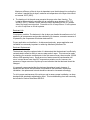
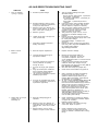
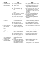
Technical Bulletin
Bulletin No.: PRO-08-05
Subject:
Effective Date: 4/1/80
Cancels:PRO-08-05 dated 6/15/78
Page: 1 of 4
AD-2 AIR DRYER INSTALLATION RECOMMENDATIONS
The thousands of Bendix Air Dryers operating successfully in the field today attest to the
success of this unique filtration device.
A key factor in the successful operation and expected service life of the air dryer is
proper installation. Several factors are to be considered:
Operational Limitations
Because the air dryer is a regenerative type device, sufficient “purge” time must be
allowed. The dryer purge cycle is controlled by the governor and occurs when the
governor is in the “cut-out” position (compressor not compressing air).
The air dryer can be used on any vehicle where normal compressor loaded time is 90
seconds or less and unloaded is 30 seconds or more. On vehicles were the compressor
remains loaded for longer periods of time, increasing the purge volume may provide for
satisfactory operation; however, in such case it is recommended that a Bendix H.V.S.G.
representative or Bendix H.V.S.G. Engineering be contacted for recommendations
before proceeding with the installation.
Installation Recommendations
1. The dryer should be mounted securely outside the engine compartment in an area of
air flow when the vehicle is in motion. Do not mount close to heat producing
components such as exhaust stacks or the exhaust system.
2. The dryer must be mounted vertically with the purge valve exhaust towards the
ground. Connection from the governor unloader port to purge valve should be a
constantly declining line. Avoid routing the line over heat producing areas (exhaust
system, etc.).
3. The air dryer is installed in the compressor discharge line, not less than six feet from
a two cylinder compressor or ten feel from a single cylinder compressor when using
copper tubing. Teflon hose or wire braid hose can be substituted for copper tubing
using a 1½’ to 1’ ratio:
Examples:
1.
Six feet of copper tubing can be replaced by nine feet of either
teflon or wire braid hose.
2.
Six feet of copper tubing can be replaced by three feet of copper
tubing plus four and one-half feet of either teflon or wire braid
hose.
Maximum efficiency of the air dryer is dependent upon the discharge line cooling the
air before it reaches the air dryer; maximum air temperature at the dryer inlet should
not exceed 150ºF (66ºC).
4. The heating unit in the end cover prevents the purge valve from freezing. The
heater is thermostatically controlled with an operating range between 45ºF (7ºC)
and 85ºF (29ºC). Number 16 wire should be used, connecting to the “on” position
side of the engine control switch. Fuse with an 8 to 10 amp fuse on 12-volt systems
or a 4 to 5 amp fuse on 24 volt systems.
Desiccant Life
Compressor condition: The desiccant in the air dryer can handle the small amount of oil
passed by all compressors and provide satisfactory life; however, excessive amounts of
oil passed by the compressor will shorten desiccant life.
Proper application and installation: As discussed previously, proper application and
installation are extremely important in achieving satisfactory desiccant life.
Desiccant Replacement
The desiccant should be replaced when it is determined that the desiccant is sufficiently
contaminated to affect its ability to remove water and oil vapor. This test can be made
by checking for excessive contaminants in the first reservoir every three months; 25,000
miles or 900 operating hours. Small amounts of water caused by condensation will
occur in areas where more than 30ºF temperature variation occurs, however, the
presence of larger amounts of liquid may be an indication that the desiccant should be
changed.
It is generally recommended that the desiccant be replaced yearly; however, if
experience has shown that shortened or extended life has resulted in a particular
installation, the replacement interval should be reduced or increased accordingly.
To aid in proper maintenance of the air dryer and to assure proper installation, we have
developed the attached troubleshooting chart. This troubleshooting chart will eventually
be included in Service Data Sheet SD-08-2.
AD-2 AIR DRYER TROUBLESHOOTING CHART
SYMPTOM
1. Dryer is constantly
“cycling” or purging.
2. Water in vehicle
reservoirs.
CAUSE
A.
Excessive system leakage.
A.
B.
B.
C.
Excessive leakage in fittings, hoses
and tubing connected to compressor,
air dryer and first reservoir.
Defective check valve between air
dryer and first reservoir. (In standard
AD-2, check valve to outlet port.)
D.
Defective governor.
D.
E.
Leaking purge valve in air dryer end
cover (control side).
E.
F.
Compressor unloader mechanism
leaking excessively.
F.
A.
Desiccant requires replacement.
A.
Replace desiccant cartridge.
B.
Improper discharge line length or
improper line material.
B.
C.
Air system charged from outside air
source (outside air not passing
through air dryer).
C.
D.
Air dryer not purging (see Symptom
#5).
Purge (air exhaust) time insufficient
due to excessive system leakage
(see causes for Symptom #1).
Air dryer/vehicle application requires
additional purge volume.
D.
Minimum of six-foot metal tubing for
two-cylinder compressor; ten-foot for
one-cylinder compressor. Flex hose
can be substituted at ratio of 1-1/2' flex hose for
each 1' of metal.
If system must have outside air fill provision,
outside air should pass through air dryer.
(Unused inlet on air dryer can be used.) Use of
this should be minimized.
See cause and remedy for Symptom #5.)
E.
Check causes and remedies for Symptom #1.
F.
When compressor is loaded (compressing)
longer than 90 seconds during normal
operation, additional purge volume may be
needed. (Before proceeding, contact Bendix
representation for consultation.)
Air dryer requires minimum purge time of 30
seconds. If compressor stays loaded longer
than 90 seconds and additional purge volume is
added, longer purge time is required. Air dryer
efficiency will decrease as compressor
loaded time increases beyond 120 seconds,
during normal operation of the vehicle. (This
limitation assumes a compressor of
approximately 12 CFM and engine operation at
1600-1900 RPM.) The air dryer will
accommodate occasional longer loaded times,
such as initial system build-up.
E.
F.
3. Safety valve on air dryer
“popping off” or
exhausting air.
REMEDY
C.
G.
Air dryer not compatible with vehicle
air system requirement - (Improper air
dryer/vehicle application).
G.
A.
Desiccant cartridge plugged or
saturated.
A.
B.
Defective check valve between air
dryer outlet port and first reservoir. (in
standard AD-2, check valve in outlet
port.)
Defective fittings, hose or tubing
between air dryer and first reservoir.
B.
C.
C.
Test for excessive leakage and repair.
Allowable leakage:
Pre-121 vehicles, single vehicle - 2 psi/minute.
Tractor trailer - 3 psi/minute.
121 vehicles, single vehicle - 1 psi/minute per
service reservoir.
Tractor trailer - 3 psi/minute per service
reservoir.
Using soap solution, test for leakage at fittings,
drain valve (if any) and safety valve in first
reservoir. Repair or replace as necessary.
Test check valve. Leakage should not exceed
1" soap bubble in five seconds. It may be
necessary to remove check valve to test.
Repair or replace as necessary.
Test governor for proper cut-in or cut-out
pressures and excessive leakage in both
positions.
Remove end cover. Apply 120 psi at control
port. Soap both sides around purge valve to test
for control piston leakage.
(Permissible leakage - 1" bubble in five
seconds.)
Remove air strainer or fitting from compressor
inlet cavity. With compressor unloaded, check
for unloader piston leakage.
Slight leakage permissible.
Check compressor for excessive oil passing
and/or correct compressor installation. Repair
or replace as necessary.
Rebuild or replace cartridge.
Test to determine if air is passing through
check valve. Repair or replace.
Check to determine if air is reaching first
reservoir. Inspect for kinked tubing or hose.
Check for undrilled or restricted hose or tubing
fittings.
SYMPTOM
4. Constant exhaust of air
at air dryer purge valve
exhaust or unable to
build system pressure.
CAUSE
A.
B.
C.
D.
E.
F.
G.
5. Air dryer does not purge
or exhaust air.
6. Desiccant material being
expelled from air dryer
purge valve exhaust
(may look like whitish
liquid or paste or small
beads).
OR
Unsatisfactory desiccant
life.
Air dryer purge valve leaking
excessively.
Defective governor.
Purge control line connected to
reservoir or exhaust port of governor.
Purge valve frozen open - faulty
heater and thermostat, wiring, blown
fuse.
Inlet and outlet air connections
reversed.
Check valve between air dryer and first
reservoir defective.
Kinked or blocked (plugged)
discharge line.
REMEDY
A.
B.
C.
D.
E.
F.
G.
With compressor loaded, apply soap solution
on purge valve exhaust, to test for excessive
leakage. Repair purge valve as necessary.
Check governor for proper “cut-in”, “cut-out”
pressure and excessive leakage in both
positions. Repair or replace as necessary.
Purge control line must be connected to
unloader port of governor.
Test for blown fuse or broken wire to air dryer.
Allow end cover to completely cool below 45°F.
End cover should be warm to touch within
moments of turning on ignition; if not, end cover
should be replaced. (Heater/thermostat not
serviceable.)
Compressor discharge to inlet port. Reconnect
lines properly.
Test check valve for proper operation (see
Symptom #3, Remedy B).
Check to determine if air passes through
discharge line. Check for kinks, bends,
excessive carbon deposits.
Discharge line should be constantly sloping
from compressor to air dryer with as few bends
as possible.
See Symptom #1’s Causes and Remedies.
H.
Excessive bends in discharge line
(water collects and freezes).
H.
I.
Excessive system leakage.
I.
A.
Broken, kinked, frozen, plugged or
disconnected purge control line.
A.
B.
Faulty air dryer purge valve.
B.
C.
See Causes B,E,F,G,H, for Symptom
#4.
C.
A.
This symptom is almost always
accompanied by one or more of
Symptoms 1,2,3,4 and 5. See related
causes for these Symptoms above.
A.
See Causes and Remedies for Symptoms 1,2,3,4
and 5.
B.
Air dryer not securely mounted.
(Excessive vibration).
B.
Vibration should be held to minimum. Add
bracket supports or change air dryer mounting
location if necessary.
C.
Defective cloth covered perforated
plate in air dryer desiccant cartridge
or improperly rebuilt desiccant
cartridge.
Compressor passing excessive oil.
C.
Replace or rebuild desiccant cartridge. NOTE:
If rebuilding cartridge, carefully follow
instructions packed with cartridge rebuild kit.
D.
D.
Test to determine air flows through purge
control line when compressor unloaded. Check
for undrilled fittings. (See Symptom #4,
Remedy C.)
After determining air reaches purge valve
(Remedy A above), repair purge valve.
Refer to Remedies B, E, F, G, H, for Symptom
#4.
E.
Faulty heater and thermostat, wiring,
fuse not allowing purge. (Cold weather
operation only.)
E.
Check for proper compressor installation; if
symptoms persist, replace compressor.
Refer to Remedy D under Symptom #4.
7. Unable to remove end
cover, or unable to install
new desiccant cartridge.
A.
Result of reversing the inlet and outlet
connections. (See Symptom #4,
Cause E.)
A.
Refer to Symptom #4, Cause E.
8. Air dryer end cover
separates from air dryer
housing during operation.
A.
Excessive system pressure build up
within air dryer; caused by either
plugged desiccant, check valve failure,
frozen or obstructed discharge line
(between air dryer and first reservoir) or
governor failure in conjunction with
safety valve failure.
A.
Because it is difficult to determine extent of
internal damage to air dryer, it is recommended
that the air dryer be replaced.
NOTE: This type of failure can be prevented by
checking the dryer for proper operation every
three (3) months.