1
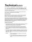
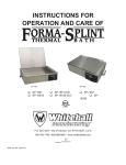
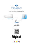
SSB-i&s--01
INSTALLATION AND SERVICE MANUAL
SPACE SAVER BOOSTER
ELECTRICAL INSTALLATION
INSTRUCTIONS
PLUMBING INSTALLATION
INSTRUCTIONS
Electric booster water heaters are available for operation on standard
power systems. Check the nameplate for the proper power supply.
For the most effective operation install the booster heater as close as
possible to the dishwasher.
All internal electrical connections have been made at the factory. See
Circuit Breaker and Fuse Sizing Chart for supply wire size, fuse,
breaker and conduit recommendations.
NOTE:
Employ recirculation if distance between booster
and dishwasher exceeds NSF specifications.
WARNING !!
For proper electrical installation conforming to local
electrical codes, consult a licensed electrical
contractor.
WARNING !!
To assure proper operation and avoid a possible
unsafe condition, the booster heater must be
installed in a horizontal position with the base
parallel to the floor and the inlet connection at the
lowest point.
WARNING !!
The main power circuit must be disconnected prior
to performing any maintenance on the booster
heater to avoid possible personal injury or damage
to the heater.
TEMPERATURE AND PRESSURE RELIEF VALVE
For protection against excessive pressures and temperatures in the
booster heater, install temperature and pressure protective equipment
required by local codes. The manufacturer supplies valves constructed
with brass working parts and heat resistant silicone seat discs for all
booster heater models.
ELECTRICAL CONNECTIONS
AL CONNECTIONS
1. Locate the heater terminal or fuse block(s) in the control box.
The control box is under the front hinged jacket cover.
WARNING !!
2. Bring power leads from a properly sized fused disconnect
switch or circuit breaker through knock-out provided in base
and connect to the terminal or fuse block(s). USE COPPER
WIRE ONLY.
Valves supplied by manufacturer are designed for
high temperature commercial operation. Do not
substitute OEM valves with valves designed for
domestic water heaters.
3. A grounding lug is provided near the supply terminals. An
equipment grounding conductor must be properly connected
to it.
Temperature/pressure protective equipment should not be less than a
combination temperature/pressure relief valve certified by a nationally
recognized testing laboratory that maintains periodic inspection of the
production of this equipment and meets the requirements for Relief
Valves and Automatic Shutoff Devices for Hot Water Supply Systems,
ANSI Z21.22-latest edition. The temperature/pressure relief valve
must be marked with a minimum set pressure not to exceed the marked
hydrostatic test pressure of the booster heater.
4. Replace and secure cover(s).
CAUTION !!
Do not turn on power to booster heater until the
tank has been filled with water and all air has been
vented through the dishwater rinse nozzle. The
heating elements will burn out in seconds if operated
when they are not immersed in water, unless the
heater is equipped with a low-water cutoff (LWCO).
1
TEMPERATURE/PRESSURE GAUGES
CAUTION !!
Manufacturer recommends a temperature/pressure gauge be installed
in both the inlet and outlet lines to the booster heater. These gauges
provide an instant visual check of the water temperature and pressure
entering the booster heater and leaving the heater. The visual check is
helpful in eliminating unnecessary service calls.
For Installing Temperature and Pressure Relief Valves
in accordance with American National Std.
Z21-22 latest edition. Combination temperature and
pressure relief valves with extension thermostats must
be installed so that the temperature-sensing element is
immersed in the water within the top 6" (152 mm) of
the tank. They must be installed either in the hot outlet
service line or directly in a tank tapping. Combination
temperature and pressure relief valves that do not
have extension elements must be mounted directly in a
tank tapping located within the top 6" (152 mm) of the
tank, and shall be adequately insulated and located so
as to assure isolation from flue gas heat or other
ambient conditions that are not indicative of stored
water temperature. To avoid water damage or
scalding due to valve operation, drain pipe must be
connected to valve outlet and run to a safe place of
disposal. Drain pipe must be as short as possible and
be the same size as the valve discharge connection
throughout its entire length. Drain line must pitch
downward from the valve and terminate at least 6"
(152 mm) above the floor drain where any discharge
will be clearly visible. The drain line shall terminate
plain, not threaded, with a material serviceable for
temperatures up to 250ºF (121ºC) or greater. Excessive
length, over 15' (4.57m), or use of more than two
elbows can cause a restriction and reduce the
discharge capacity of the valve. No shut-off valve shall
be installed between the relief valve and tank, or in the
drain line. Valve lever must be tripped periodically to
insure that waterways are clear. This device is
designated for emergency safety relief and shall not be
used as an operating control. Do not use an antisiphon
or check valve on the incoming water line.
PLUMBING CONNECTIONS
CAUTION !!
To avoid development of a leak, do not back up or
loosen any pipe fittings.
WARNING !!
Do not connect the heater directly to a boiler or
furnace coil or any other uncontrolled temperature
source. Such hook-up could cause the thermostat to
lose control and the unit could overheat.
WARNING:
INLET
CAUTION !!
The valves are set to relieve at 150 psi or when water
temperature reaches 210°F (99°C). Read tag on
valve for additional information.
Connect the booster heater water inlet to a hot water supply line from
the regular water heater. Water temperature from the regular water
heater should be 100°F or 140°F (52°C or 60°C) and should not exceed
160°F (71°C). Minimum temperature differential between inlet and
outlet temperatures should never be less than 20°F (11°C). Provide the
inlet line with a shut-off valve, a full open gate or ball type valve,
together with a pressure reducing valve. Set pressure reducing valve at
20 psi (1.4 kg/cm2) flow pressure.
PRESSURE REDUCING VALVE
Proper operation of the dishwater rinse nozzles requires available
water pressure at the nozzle be between 15 and 25 psi when nozzle is
operated. 20 psi is recommended.
NOTE:
If water pressure available to the booster heater inlet is over 20 psi, a
pressure reducing valve should be mounted in the hot water supply line
to the booster heater.
Be sure water flows through the pressure reducing
valve in the proper direction. Check directional
arrow. Valve will reduce pressure only during flow
conditions.
The pressure reducing valve supplied by the manufacturer has a
built-in high pressure by-pass which prevents excessive pressure buildup as the booster heats up.
A 3/4 in. union fitting and a drain valve are needed for easy servicing.
2
CAUSE B
If incoming water temperature is correct and it holds through the
dishwashing operation, another possible reason for this condition is
that the water pressure may be too high. Water pressure to the
dishwasher must be approximately 20 psi for proper operation of the
booster and dishwasher rinse cycle.
NOTE:
Do not run a cold water line to the heater.
OUTLET
SOLUTION - If pressure exceeds 20 psi with the
dishwasher rinse valve open, install a pressure reducing
valve with built in bypass check.
Using a 3/4 in. union and piping connect the booster heater water outlet
to the dishwasher sanitizing rinse pipe connection.
NOTE:
CAUSE C
The booster may be undersized.
Be certain the connection is made to the final rinse
and not to the wash tank.
SOLUTION - Check the dishwasher model with the sizing
guide to be sure the correct booster has been installed.
CAUSE D
The booster may have been ordered with improper voltage.
Install a temperature/pressure gauge in outlet line. Water temperature
at outlet should be 180°F (82°C). The temperature sensing element
must be in water stream.
SOLUTION - Consult specifications plate on the booster.
Voltage and amperage are clearly marked. Check this information against the service to which it is connected. If heater
was incorrectly specified consult factory for instructions.
Manufacturer recommends a shock absorber be installed in the outlet
line as close as possible to the dishwasher The shock absorber softens
the water hammer caused by automatic dishwasher valves.
CAUSE E
A low voltage condition may exist. Low voltage is a common cause on
large model heaters.
INSTALLATION CHECK
INSTALLATION CHECK
1. Close drain pipe valve and fill booster heater with water.
SOLUTION - Verify wire size and circuit for the application.
2. Check all pipe connections for installation leaks.
THE BOOSTER HEATER DOES NOT HEAT AT ALL OR ONLY
DELIVERS 130-150ºF (54ºC - 66ºC) WATER.
3. Check relief valve discharge opening to be certain it is not blocked.
4. Vent air from tank before operating.
CAUSE A
Sometimes upon completion of an installation, the booster operation is
checked by energizing the heater before the tank is completely filled
with water. When elements of the immersion type are not completely
covered by water at the time the heater is turned ON, the high
temperature in the tank may damage the element(s) unless the unit has
been equipped with a low water cut-off.
CAUTION !!
Leave tank filled with water during electrical
hookup to prevent possible element burnout.
SOLUTION - Damaged elements must be replaced.
BOOSTER HEATER SERVICE
PROCEDURES
NOTE:
Thermostats should also be inspected. Elements
damaged by overheating in “dry” environment can
easily damage thermostats.
WATER REACHES 180ºF (82ºC), BUT DOES NOT MAINTAIN
180ºF THROUGH THE ENTIRE DISHWASHING OPERATION.
CAUSE A
Low incoming temperature, particularly during peak operational
periods, is the most common cause of this condition. If incoming
temperature is correct at the start of the dishwashing operation, check
again at the end. It is possible for the supply of 140ºF (60ºC) water to
be exhausted during the washing cycle.
CAUSE B
Fuses may be blown or circuit breaker tripped.
SOLUTION - Inspect the fuses or circuit breaker and
refer to data sheet for the booster model installed. If
undersized fuses or circuit breakers were installed, replace
with size recommended in the data sheet. See Section
“Booster repeatedly blows fuses or trips circuit breakers.”
SOLUTION - If incoming temperature is 140ºF (60ºC) at
the start of the washing cycle, but falls below at the end,
the primary water heater is not delivering sufficient 140ºF
(60ºC) water and the condition is correctable with
installation of a commercial primary water heater model of
the correct size. Contact your representative to assure proper
sizing of the primary heater.
3
(77ºC). Make certain the thermostats are set to their maximum
calibration. They are pre-set at the factory to 190ºF (88ºC) to
compensate for heat loss but they may have been turned down to 180ºF
(82ºC) by someone overlooking heat loss through the pipes.
CAUSE C
Thermostats may not be functioning correctly or may be improperly set.
SOLUTION - Inspect thermostats for proper operation and
correct settings. If setting is below the maximum, reset to
190ºF(88ºC) If defective and not functioning, replace.
SOLUTION - The booster should be moved to within 5 feet
of the dishwasher if possible, and the pipes should be
insulated.
CAUSE D
Contactors are not performing.
CAUSE B
Thermostats may not be functioning correctly.
SOLUTION - Inspect contactors for proper operation by
visual observation. Assuming no fuses are blown and
power is coming to the booster, inspect the coil and replace
if defective.
NOTE:
To help determine this cause, check rinse
temperature in the dishwasher. Since the dishwasher
temperature gauge could become defective, it is
preferable to rely on a temperature sensitive tape or
a thermometer rather than the gauge for checking
this cause.
CAUSE E
ECO (high temperature limit switch) may be defective.
SOLUTION - Check for proper operation and replace if
defective.
CAUSE F
The fuse is blown.
SOLUTION - If maximum reading is below 180ºF, (82ºC)
first turn the pointers all the way up on all thermostats. If
the reading is still below 180ºF (82ºC), minor adjustments
can be made on the thermostats. If recalibration does not
help, the thermostat is defective and should be replaced.
SOLUTION - Replace fuse. If fuse continues to blow, either a
contactor coil is defective, or the booster control transformer
is defective. If booster has more than one contactor,
disconnect wires so only one contactor at a time is energized.
The defective one can then be isolated and replaced.
BOOSTER HEATER REPEATEDLY BLOWS FUSES OR TRIPS
CIRCUIT BREAKERS.
On all boosters with low water cut-off, the following trouble shooting
procedures apply.
NOTE:
CAUSE G
Relay does not pull in after booster is filled with water and air bled out.
Fuses or circuit breakers should not be loaded to
more than 80% of their rating.
SOLUTION
CAUSE A
Fuses are undersized-too small to carry the load.
1. Check for voltage at line terminals 1 and 2 using volt-meter
or test light. If there is no voltage, refer to CAUSE F.
SOLUTION - Check “Fuse and Disconnect Switch Sizes”
table for recommended sizes. Replace undersized fuses
with correct one.
2. Open circuit between ground and the probe. Check for
broken wire or poor contact at connections. To test, run
temporary wires from probe terminal #3. If relay pulls in,
the wire is broken and should be replaced.
CAUSE B
Short circuit in internal heater wiring.
3. Check or open relay coils. With line voltage applied at 1
and 2, connect a jumper wire between 6 and 7. Relay
should pull in when the jumper is connected and fall out
when the jumper is removed. Failure to do so indicates
one of the coils is open and the relay should be replaced.
SOLUTION - By visual inspection check for: loose
connections, grounded heating elements, frayed insulation
and foreign matter touching wiring terminals.
WHEN THE DISHWASHER AND THE BOOSTER HAVE BEEN
IDLE FOR SEVERAL HOURS, RELIEF VALVE OPENS OR
ECO TRIPS.
4. Fouled probe. If solution 2 discloses no broken wire or poor
connection and relay still does not pull in, probe tip may be
insulated by lime buildup. If relay operates when a jumper
wire is connected between terminals 3 and ground, the
probe is fouled. Remove probe and clean the electrode.
CAUSE A
A cause of overheating and resulting relief is excessive primary water
temperature. Primary water temperature should not exceed 160ºF (71ºC).
TEMPERATURE
REACHES
ONLY
170-175ºF
(77ºC - 79ºC). THIS CONDITION AS DIFFERENTIATED
FROM CONDITION II INDICATES THE BOOSTER HEATER
IS FUNCTIONING, BUT MAY NOT BE REACHING PROPER
TEMPERATURE (180ºF, 82ºC).
SOLUTION - Check to be sure primary water heater is
functioning properly. Primary water heater thermostats
may be set too high, causing nuisance tripping. Adjust
primary heater thermostats to 140-150ºF (60ºC - 66ºC).
CAUSE A
Booster should be close to the dishwasher, (5 feet or less). If the
booster is more than 5 feet away, the heat loss through the pipes is the
most likely reason the dishwasher thermometer reads only 170ºF
4
CAUSE B
Control thermostat may be set too high or be defective.
CAUTION !!
Do not overtighten nut, or sleeve inside of bushing
will cut through tubing.
SOLUTION - Reset thermostat(s). If condition is not
corrected, replace thermostat(s).
CHATTERING CONTACTOR(S) OR NOISY RELAY.
4.
CAUSE A
Contactors chatter or hum excessively when pulled in.
SOLUTION - Accumulation of dirt will prevent proper
seating of armature. Remove contactor and clean. If proper
seating is prevented by warpage of the frame or distorted
coil, contactor should be replaced. Check for loose
connections or wire connections with insulation under crimp.
CAUTION !!
Be sure tank is filled with water before turning on power.
CAUSE B
Contactors chatter only at pull-in or drop-out, or low water cutoff relay
is noisy.
SOLUTION - Check for low voltage at control circuit and
at secondary side of transformer. If voltage is below 120
volts, replace transformer. Low water cutoff probe may be
fouled. To check, remove wire from LWCO probe and
ground to tank. If LWCO board relay pulls in and stops
chattering, the probe is fouled. To clean, drain water from
tank, remove probe and clean probe tip.
THERMOSTAT
ADJUSTMENT AND RECALIBRATION
The thermostats are factory calibrated to produce 185-190ºF
(85-88ºC) temperatures. If recalibration is necessary, turn screw (G)
counterclockwise to lower the set point or turn the adjustment nut (F)
counterclockwise to raise the set point (must hold screw (G) at high
stop). NOTE: one-sixth of a turn equals 12ºF (6.7ºC).
These thermostats are checked and accurately set at out factory. If
recalibration is necessary, a 1/4 turn clockwise to screw (F) will
decrease the temperature 12ºF (6.7ºC).
REMOVAL
1.
2.
Shut off power and drain tank; remove leads from
terminals (E).
Loosen nut (A), then remove bushing (B) from tank.
Thermostat with bracket and sensor bulb (C) can now
be removed from tank.
INSTALLATION
1.
2.
3.
Replace thermostat on bracket. Replace leads
on thermostat terminals.
Pull end of sensor bulb (C) into recess in bushing (B).
Insert bushing (B) and sensor bulb into tank;
holding sensor bulb in place with capillary tube,
tighten bushing (B).
Lock sensor bulb and capillary tube in place by
tightening nut (A).
5
HIGH TEMPERATURE LIMIT SWITCH
RECALIBRATION
If the temperature in the heater exceeds 210ºF (99ºC), the high
temperature limit will shut off the power. The switches must be
manually reset by pushing the red buttons. The limit switch has been
calibrated at the factory and should not require adjusting. If the
calibration changes and must be re-adjusted, the procedure is as
follows:
Models 4-18kW
Hold lock nut (F) and turn calibrating screw (G) clockwise 1/8
turn to increase set point 7ºF (3.9ºC), or hold screw (G) and turn
nut (F) clockwise.
Model 24 - 58kW
Turn adjustable screw (D) clockwise to raise set point
- 1/8 turn equals about 7ºF (3.9ºC).
REMOVAL
1.
2.
3.
Shut off power and drain tank; remove leads from
terminals (E).
Remove two screws holding the switch on the bracket.
Loosen nut (A), then remove bushing (B) from tank.
The high limit switch and sensor bulb (C) can now be
removed from tank.
INSTALLATION
1.
2.
3.
Pull end of sensor bulb (C) into recess in bushing (B).
Insert bushing (B) and sensor bulb into tank; holding
sensor bulb in place with capillary tube, tighten bushing (B).
Lock sensor bulb and capillary tube in place by
tightening nut (A).
CAUTION !!
Do not overtighten nut, or sleeve inside of bushing
will cut through tubing.
4.
Replace switch on bracket. Replace leads on terminals.
CAUTION !!
Be sure tank is filled with water before turning on power.
6
CIRCUIT BREAKER AND FUSED DISCONNECT SWITCH SIZES
kW
6
9
12
15
18
24
30
36
45
54
58
VOLTS
208
208
240
240
480
208
208
240
240
480
208
208
240
240
480
208
208
240
240
480
208
208
240
240
480
208
208
240
240
480
208
208
240
240
480
208
208
240
240
480
208
240
240
480
208
240
480
208
240
480
PH
1
3
1
3
3
1
3
1
3
3
1
3
1
3
3
1
3
1
3
3
1
3
1
3
3
1
3
1
3
3
1
3
1
3
3
1
3
1
3
3
3
1
3
3
3
3
3
3
3
3
L1
29
14
25
13
6
43
22
38
19
9
58
33
50
29
14
72
42
63
36
18
87
48
75
43
22
115
67
100
58
30
144
83
125
72
36
173
100
150
87
43
125
188
108
54
150
130
65
162
141
71
L2
29
25
25
22
11
43
38
38
33
16
58
33
50
29
14
72
42
63
36
18
87
48
75
43
22
115
67
100
58
30
144
83
125
72
36
173
100
150
87
43
125
188
108
54
150
130
65
162
141
71
L3
—
14
—
13
6
—
22
—
19
9
—
33
—
29
14
—
42
—
36
18
—
48
—
43
22
—
67
—
58
30
—
83
—
72
36
—
100
—
87
43
125
—
108
54
150
130
65
162
141
71
Breaker or Fuse Size Copper Wire Size
40
8
40
8
40
8
30
10
15
14
60
6
50
8
50
8
50
8
20
12
90
3
50
8
70
4
40
8
20
12
90
3
60
6
90
3
50
8
30
10
125
1
60
6
100
3
60
6
30
10
150
1/0
90
3
125
1
90
3
40
8
200
3/0
125
3
175
2/0
100
3
50
8
225
4/0
125
1
200
3/0
125
1
60
6
175
2/0
250
250 MCM
150
1/0
70
4
200
3/0
175
2/0
90
3
225
4/0
200
3/0
90
3
Conduit Size
1/2”
3/4”
1/2”
1/2”
1/2”
3/4”
3/4”
1/2”
3/4”
1/2”
1”
3/4”
1”
3/4”
1/2”
1”
3/4”
1”
3/4”
1/2”
1-1/4”
3/4”
1”
3/4”
1/2”
1-1/4”
1-1/4”
1-1/4”
1-1/4”
3/4”
1-1/2”
1-1/2”
1-1/2”
1-1/4”
3/4”
2”
1-1/2”
1-1/2”
1-1/2”
3/4”
2”
2”
1-1/2”
1”
1-1/2”
2”
1-1/4”
2”
1-1/2”
1-1/4”
Wire size is based on THHN wire for branch circuit protection at .91 derate factor. Circuit breakers are to be mounted remotely and wired by the contractor. Sizes are
based on the NEC table 310-16. Conduit size is based on conductors plus ground wire sizing as per NEC table 250-122.
7
DIMENSIONS
HANGING SUPPORT
8
PLUMBING CONNECTIONS
9
10
11
CP-2M-4/03-Printed in U.S.A.