1
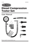
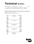
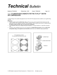
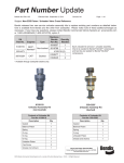
Technical Bulletin
Bulletin No: TCH-001-059
Subject:
Effective Date: 10-20-2010
Cancels: N/A
Page: 1 of 2
Pulley-Driven Compressor Mounting Position
Bendix® Tu-Flo® 550 pulley-driven, base-mounted compressors installed on certain Navistar® V-8 engines
may have a metal tag under the front-left mounting bolt, as shown below. If the compressor with this metal
tag is removed during engine service, please use the following procedure to re-install the compressor.
(Note: this procedure does not apply if replacing the compressor with a different unit.)
Pulley
Front-left Mounting Hole
Bendix® Tu-Flo® 550 Compressor
Front-left Mounting Bolt
Metal Tag
ATTN: PRIOR TO LOOSENING
THE MOUNTING BOLTS, CALL
1-800-AIR-BRAKE FOR INFO.
WWW.BENDIX.COM TCH-001-059
BENDIX® TU-FLO® 550 COMPRESSOR RE-INSTALLATION PROCEDURE
Be sure to follow all safety guidelines outlined in the Bendix® Tu-Flo® 550 Compressor Service
Data Sheet SD-01-337 before performing any maintenance procedures.
1. Clean the bottom surface of the Tu-Flo® 550 compressor and top surface of the compressor mounting
bracket.
2. Install a new gasket between the compressor and the compressor mounting bracket as specified by
the OEM.
Continued...
Page: 2 of 2
Bulletin No: TCH-001-059
3. Mount the compressor and mounting gasket on the compressor mounting bracket and loosely install
the four (4) compressor (M10) mounting bolts previously removed.
4. Using a feeler gauge, measure the distance between the shoulder of the front-left mounting bolt and the
front flange of the compressor, as shown below.
Front-left
Mounting Bolt
Compressor
Mounting Flange
0.8 – 4.3 mm
(Verify using
Feeler Gauges)
Feeler Gauge
(0.8 mm)
Front-left
Mounting Bolt
Feeler Gauge
(4.3 mm)
Front-left
Mounting Bolt
Compressor Movement
Compressor Flange
Compressor Flange
Compressor Mounting
Bracket
Compressor Mounting
Bracket
Compressor
Movement
5. Move the compressor toward the front (pulley side) or back until a feeler gauge reading between 0.8
and 4.3 mm is reached.
6. Using the torque specified by the OEM, tighten three (3) of the mounting bolts, leaving the front-left
mounting bolt loose.
7. Remove the front-left mounting bolt and re-install the metal tag in its original location under the front-left
mounting bolt.
8. Tighten the front-left mounting bolt using the same OEM specified torque used on the other three
mounting bolts.
9. Follow the Service Data Sheet, SD-01-337, for “Testing Rebuilt Compressor” before placing the vehicle
into service.
© 2010 Bendix Commercial Vehicle Systems LLC All rights reserved. 10/2010 Printed in U.S.A.