1
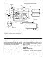
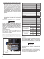
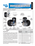
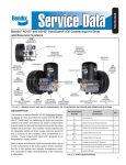
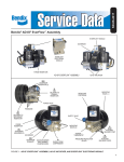
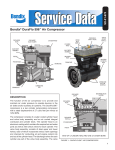
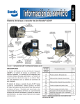
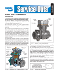
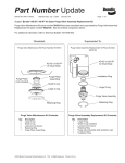
SD-08-2417
®
Bendix® AD-IS® EverFlow® Assembly
EVERFLOW MODULE
GOVERNOR
BENDIX
EVERFLOW®
ELECTRONIC
MODULE
PURGE RESERVOIR
BENDIX® AD-IS® EVERFLOW® ASSEMBLY
BENDIX® AD-IS® AIR DRYER
RES
GOVERNOR
RESERVOIR (2)
PURAGUARD®
MEDALLION
PURGE VALVE
MOUNTING
HOLES - 4
DESICCANT
CARTRIDGE
PRESSURE
PROTECTION
VALVES (4)
GOVERNOR
SAFETY
VALVE
PURGE
RESERVOIR
MOUNTING
BOLTS (3)
UNL
GOVERNOR
UNLOADER (2)
22
SEC
DELIVERY TO
SECONDARY
RESERVOIR
21
PRI
DELIVERY TO
PRIMARY
RESERVOIR
EXH
GOVERNOR
EXHAUST
AD-IS® AIR
DRYER PART
NUMBER
STAMPED HERE
1
IN
SUPPLY FROM
COMPRESSOR
23
AUX2
AUXILIARY
DELIVERY PORT
HEATER /
THERMOSTAT
PRESSURE
PROTECTION
VALVES (4)
24
AUX1
AUXILIARY
DELIVERY PORTS
FIGURE 1 - BENDIX® AD-IS® EVERFLOW® ASSEMBLY, AD-IS® AIR DRYER, AND EVERFLOW® ELECTRONIC MODULE
1
GENERAL SAFETY GUIDELINES
WARNING! PLEASE READ AND FOLLOW THESE INSTRUCTIONS
TO AVOID PERSONAL INJURY OR DEATH:
When working on or around a vehicle, the following guidelines should be observed AT ALL TIMES:
▲ Park the vehicle on a level surface, apply the
parking brakes and always block the wheels.
Always wear personal protection equipment.
▲ Stop the engine and remove the ignition key
when working under or around the vehicle.
When working in the engine compartment,
the engine should be shut off and the ignition
key should be removed. Where circumstances
require that the engine be in operation, EXTREME
CAUTION should be used to prevent personal
injury resulting from contact with moving,
rotating, leaking, heated or electrically-charged
components.
▲ Do not attempt to install, remove, disassemble
or assemble a component until you have read,
and thoroughly understand, the recommended
procedures. Use only the proper tools and
observe all precautions pertaining to use of those
tools.
▲ If the work is being performed on the vehicle’s
air brake system, or any auxiliary pressurized air
systems, make certain to drain the air pressure
from all reservoirs before beginning ANY work
on the vehicle. If the vehicle is equipped with a
Bendix® AD-IS® air dryer system, a Bendix® DRM™
dryer reservoir module, or a Bendix® AD-9si™ air
dryer, be sure to drain the purge reservoir.
▲ F o l l o w i n g t h e v e h i c l e m a n u f a c t u r e r ’s
recommended procedures, deactivate the
electrical system in a manner that safely removes
all electrical power from the vehicle.
▲ Never exceed manufacturer’s recommended
pressures.
▲ Never connect or disconnect a hose or line
containing pressure; it may whip. Never remove
a component or plug unless you are certain all
system pressure has been depleted.
▲ Use only genuine Bendix ® brand replacement
parts, components and kits. Replacement
hardware, tubing, hose, fittings, etc. must be of
equivalent size, type and strength as original
equipment and be designed specifically for such
applications and systems.
▲ Components with stripped threads or damaged
parts should be replaced rather than repaired.
Do not attempt repairs requiring machining or
welding unless specifically stated and approved
by the vehicle and component manufacturer.
▲ Prior to returning the vehicle to service, make
certain all components and systems are restored
to their proper operating condition.
▲ For vehicles with Automatic Traction Control
(ATC), the ATC function must be disabled (ATC
indicator lamp should be ON) prior to performing
any vehicle maintenance where one or more
wheels on a drive axle are lifted off the ground
and moving.
▲ The power MUST be temporarily disconnected
from the radar sensor whenever any tests USING
A DYNAMOMETER are conducted on a Bendix®
Wingman® Advanced™-equipped vehicle.
▲ You should consult the vehicle manufacturer's operating and service manuals, and any related literature,
in conjunction with the Guidelines above.
DESCRIPTION
The function of the Bendix® AD-IS® EverFlow® assembly is
to provide heavy vehicles that use large amounts of air with
a dryer system that facilitates continuous flow drying. This
assembly provides, in a single package, all the components
necessary to operate two dryers. The assembly determines
if high air demand is needed and continuously switches
between dryers every 30 seconds until the high air demand
ceases. When high air demand is not needed, the assembly
uses the dryers as if in a normal braking system. Each
dryer cycles as the air brake system requires. This feature
prevents wasted air and unnecessary cycles. The assembly
uses an electronic module that determines air demand and
sequences the dryers for maximum efficiency.
2
The Bendix® AD-IS® air dryer collects and removes air
system contaminants in solid, liquid and vapor form before
they enter the brake system. It provides clean, dry air to
the components of the brake system which increases the
life of the system and reduces maintenance costs. Daily
manual draining of the reservoirs is eliminated, but still may
be mandated by law.
The function of the pressure protection valves is to protect
each reservoir from a pressure loss in the other reservoir or
a pressure loss in an air accessory. Each of the pressure
protection valves in the AD-IS air dryer may have different
pressure settings, but these are factory set and must not
be changed or adjusted.
Bendix® EverFlow® Electronic Module
Governor
GOV
CON
RES
3/8"
CON
Schrader
Valve
From
Engine
SEC
RES
Supply
IN
CON
CON
CON
Primary
Reservoir
1/2"
PRI
1/2"
CON
OUT
Bendix®
AD-IS®
Air Dryer
Accessories
Compressor
Bendix® AD-IS®
EverFlow® Assembly
IN
1/4"
Dryer OUT
CON
EverFlow®
IN
Secondary
Reservoir
AD-IS
Air Dryer
Check
Valve
CON
Supply
IN
Pressure
Protection Valve
Manual Valve
Bulk Offload CTI
CTI System
Bulk Tanker
Compressor
OUT
Discharge Line
Unloader Valve
Note:
The Bendix® AD-IS® air dryer purge piston has a purge control
channel drain. This allows any condensation in this area to flow
past a diaphragm in the top of the purge piston and out through
a channel in the middle of the central bolt of the purge assembly
to be drained. During the purge cycle this drain is closed.
FIGURE 2 - BENDIX® AD-IS® AIR DRYER SYSTEM SCHEMATIC
The air dryer consists of a “spin on” desiccant cartridge
secured to a base assembly. The base assembly contains
a delivery check valve assembly, safety valve, heater and
thermostat assembly, pressure protection valves, threaded
air connections, and the purge valve assembly.
These units will not operate properly with a Holset-type
compressor. For discharge line unloaded compressors
a three way valve must be installed upstream of the air
dryer. Contact Bendix Commercial Vehicle Systems for
additional information.
The removable purge valve assembly incorporates the
purge valve mechanism and a turbocharger cut-off feature
that is designed to prevent loss of engine “turbo” boost
pressure during the purge cycle of the Bendix® AD-IS® air
dryer. For ease of maintenance, all replaceable assemblies
can be serviced without removal of the air dryer from
its mounting on the vehicle. Refer to the Preventative
Maintenance section.
BENDIX ® AD-IS ® EVERFLOW ® ASSEMBLY
OPERATION
GENERAL (Refer to Figure 2)
The Bendix® AD-IS® EverFlow® assembly is designed to
receive compressed air from the vehicle air compressor.
It then cleans and dries the air before delivering it to
the vehicle’s primary reservoir, secondary reservoir and
accessories. Additionally, the AD-IS EverFlow assembly
controls the compressor/dryer charge cycle.
3
Note 1:
DESICCANT
BED
The Bendix AD-IS® air dryer and reservoir
system purge piston has a purge control
channel drain. This allows any condensation
in this area to flow past a diaphragm in the
top of the purge piston and out through a
channel in the middle of the central bolt of
the purge assembly to be drained. During
the purge cycle this drain is closed.
®
OIL COALESCING FILTER
(BENDIX® AD-IS® PURAGUARD®
OIL COALESCING AIR DRYER)
PURGE
CONTROL
CHANNEL
PURGE
ORIFICE
DELIVERY
CHECK VALVE
(OPEN)
PURGE
RESERVOIR
PRESSURE
PROTECTION
VALVES
GOVERNOR
UNLOADER
PORT
SUPPLY
PORT
A
PURGE VALVE
(CLOSED)
TURBO
CUT-OFF
VALVE
ENGINE (OPEN)
TURBO
COMPRESSOR
SAFETY
VALVE
B
C
D
PRIMARY
PORT (PRI)
PURGE
RESERVOIR
DRAIN VALVE
SECONDARY
PORT (SEC)
SEE
NOTE 1
PRIMARY
RESERVOIR
SECONDARY
RESERVOIR
AUXILIARY PORTS
(TO ACCESSORIES)
FIGURE 3 - BENDIX® AD-IS® AIR DRYER AND RESERVOIR SYSTEM CHARGE CYCLE
AD-IS EVERFLOW AIR DRYER OPERATION:
GENERAL
The Bendix ® AD-IS ® EverFlow ® assembly alternates
between the dryers each time the brake system charges.
During high air demand, the dryers alternate every 30
seconds to allow drying of the added volume of air. A
pressure protection valve is needed after the dryers to
maintain at least 70 PSIG at the dryers during high air
demand. A Bendix® EverFlow® electronic module monitors
the air brake system and determines the amount of
demand. The AD-IS EverFlow assembly requires a
signal from the delivery port of the governor into the
GOV port of the EverFlow electronic module. The AD-IS
EverFlow assembly also needs a supply air line from the
secondary tank to the electronic module RES port. This
line must be 3/8 inch, or larger, tubing.
4
The AD-IS EverFlow assembly is primarily designed to dry
air on systems used for bulk unload and central tire inflation.
The system operates best when a pressure protection valve
is installed between the EverFlow assembly and the source
of the high volume air. Refer to the system schematics,
Figure 2. This pressure protection valve should have a
minimum pressure of 70 PSIG. Delivery pressure in
excess of 175 PSIG can cause the purge valve to cycle
rapidly between load and purge mode.
NORMAL BRAKE CYCLE (Refer to Figures 3 & 4)
When the compressor is charging (compressing air) air
flows through the compressor discharge line to the inlet
(1 IN) port of one of the air dryers. The compressed air
includes contaminates such as oil, oil vapor, water and
water vapor. The air then flows into the desiccant cartridge,
where it flows through a liquid separator which collects
liquids and other contaminants.
DESICCANT
BED
OIL COALESCING FILTER
(BENDIX® AD-IS® PURAGUARD®
OIL COALESCING AIR DRYER)
PURGE
CONTROL
CHANNEL
PURGE
ORIFICE
DELIVERY
CHECK VALVE
(CLOSED)
PURGE
RESERVOIR
PRESSURE
PROTECTION
VALVES
GOVERNOR
UNLOADER
PORT
SUPPLY
PORT
A
PURGE VALVE
(OPEN)
TURBO
CUT-OFF
VALVE
ENGINE (CLOSED)
TURBO
COMPRESSOR
SAFETY
VALVE
B
C
D
PRIMARY
PORT (PRI)
PURGE
RESERVOIR
DRAIN VALVE
SECONDARY
PORT (SEC)
EXHAUST
PRIMARY
RESERVOIR
SECONDARY
RESERVOIR
AUXILIARY PORTS
(TO ACCESSORIES)
DIAGRAM SHOWS ALL PRESSURE
PROTECTION VALVES OPEN.
FIGURE 4 - BENDIX® AD-IS® AIR DRYER AND RESERVOIR SYSTEM PURGE CYCLE
Air then moves into the desiccant drying bed and becomes
progressively drier as water vapor adheres to the desiccant
material in a process known as “ADSORPTION.” Dry air
exits the desiccant cartridge through the delivery check
valve and also through an orifice into the purge reservoir.
The delivery check valve opens, supplying air to pressurize
the air brake system. The purge reservoir stores air that will
be used to reactivate the desiccant during the purge cycle.
From a flat system — approximately 80 psi — the Bendix®
AD-IS® EverFlow® electronic module is actuated and
begins the purge cycle. When the air pressure reaches
the specified opening pressure — typically 106 psi — the
pressure protection valves will open and air will be supplied
to the primary reservoir, secondary reservoir or other
accessories. If the pressure protection valves are preset
to different values, the valves will open in order of lowest
setting to highest setting when charging a flat system.
The air dryer will remain in the charge cycle until the air
brake system pressure builds to the governor cut-out
setting of approximately 130 psi When air brake system
pressure reaches the cut-out setting of the governor,
the governor unloads the compressor and the electronic
module sends a signal to one of the air dryers to purge.
The governor unloads the compressor by allowing air
pressure to fill the line leading to the compressor unloader
mechanism — causing the delivery of compressed air to
the Bendix® AD-IS® EverFlow® assembly to be suspended.
Similarly, the governor also supplies air pressure to the
EverFlow electronic module. The electronic module uses
this signal to determine the volume of air in the brake
system. If the volume is normal, the electronic module
sends a signal to the control port on the proper dryer. If the
5
volume is high, the electronic module switches the dryers
every 30 seconds until the air volume demand returns to
normal. The air dryer purge piston moves down in response
to a pneumatic signal from the Bendix® AD-IS® EverFlow®
electronic module, causing the purge valve to open to
the atmosphere and the turbo cut-off valve to close off
the supply of air from the compressor (this will be further
discussed in the Turbo Cut-off Feature section). Water
and contaminants which have collected in the dryer are
expelled immediately when the purge valve opens. Also, air
which was flowing through the desiccant cartridge changes
direction and begins to flow toward the open purge valve.
Liquids and other contaminants collected by the liquid
separator are removed by air flowing from the purge
reservoir through the desiccant bed to the open purge valve.
The initial purge and desiccant cartridge decompression
lasts only a few seconds and is evidenced by an audible
burst of air at one of the Bendix® AD-IS® EverFlow®
assembly’s purge exhaust. The actual reactivation of the
desiccant bed begins as dry air from the purge reservoir
flows through the purge orifice into the desiccant bed.
Pressurized air from the purge reservoir expands after
passing through the purge orifice.
The flow of dry air through the drying bed removes water
vapor from the desiccant material. The purge lasts 30
seconds. The delivery check valve assembly prevents air
pressure in the brake system from returning to the purging
air dryer during the purge cycle. After the purge cycle is
complete, the air dryer is ready for the next charge cycle
to begin.
Air Connection
Port ID
1
IN
Function/
Connection
Inlet Port (air in)
1
21
PRI
Delivery Port Out (to Primary Reservoir)
1
22
SEC
Delivery Port out (to Secondary
Reservoir)
1
24
AUX 1
Auxiliary Delivery Port (air out)
4
23
AUX 2
Auxiliary Delivery Port (air out)
1
UNL
Unloader Control Air (D-2A™ Governor)
2
RES
Common Reservoir Pressure
(D-2A Governor)
2
EXH
Governor Exhaust
1
TABLE 1 - BENDIX® AD-IS® AIR DRYER PORT
DESIGNATIONS
6
QTY
TURBO CUT-OFF FEATURE
The primary function of the turbo cut-off valve is to prevent
loss of engine turbocharger air pressure through the AD-IS
EverFlow assembly when both dryers are in the unloaded
mode. At the onset of the purge cycle, the downward travel
of the purge piston is stopped when the turbo cut-off valve
(tapered portion of purge piston with a soft seat) contacts
its mating metal seat in the purge valve housing. With
the turbo cut-off valve seated (closed position), air in the
compressor discharge line and AD-IS EverFlow assembly
inlet port cannot pass through the air dryer. In this manner
the turbo cut-off effectively maintains turbo charger boost
pressure to the engine. Delivery pressure in excess of
175 PSIG can cause the purge valve to cycle rapidly
between load and purge mode. All AD-IS EverFlow
assemblies require a soft seat purge valve.
HIGH VOLUME MODE
If the GOV port of the electronic module indicates that the
compressor has been charging for longer than 30 seconds,
the dryers will alternatively purge every 30 seconds. This
is an indication of high volume through the dryer. When
the governor signal indicates the charge cycle is complete,
the assembly returns to normal brake cycling.
PREVENTATIVE MAINTENANCE
For Bendix® AD-IS® EverFlow® air dryers: Preventative
Maintenance is as easy as 1-2-3
Adhering to a preventative maintenance schedule is
crucial to keeping a vehicle’s air system clean and
ensuring superior performance of all components that
utilize system air — such as brakes, emissions equipment
and automated manual transmissions. Depending on
vocation, Bendix recommends a 1, 2 or 3-year air dryer
cartridge replacement on vehicles equipped with a Bendix®
compressor.
For severe service application — such as residential refuse
trucks or school buses — the air dryer cartridge should
be replaced every year or 100,000 miles; for pick-up
and delivery operations, or for double- and triple-trailer
line haul trucks, every two years or 200,000 miles is the
recommendation. Line-haul operations using a single trailer
should swap the filter out every three (3) years or 300,000
miles. The recommended intervals for trucks equipped with
non-Bendix compressors are 6 months (50,000 miles),
one year (100,000 miles) and two years (200,000 miles),
respectively.
More frequent intervals may be required depending
on a vehicle’s age, its compressor condition, use of a
non-Bendix compressor, the operating environment, the
vehicle’s vocation, and its usage. In conjunction with these
guidelines, fleets can determine the functionality of their
filters by checking for moisture in the air brake system
monthly. If moisture is present, the air dryer cartridge may
require replacement. Reference the Bendix Service Data
Sheet of the specific air dryer for additional information.
(Recommended intervals for trucks equipped with nonBendix compressors are 6 months (50,000 miles), one
year (100,000 miles) and two years (200,000 miles),
respectively.)
Notes:
1. Replace both desiccant cartridges at one time. Failure
to change both could cause one dryer to pass wet air
and the other dryer to pass dry air. This would lead to
a wet brake system.
2. A small amount of oil in the system is normal and should
not be considered as a reason to replace the desiccant
cartridges. Oil at the dryer purge exhaust is normal.
3. Visually check for physical damage such as chaffed or
broken air and electrical lines and broken or missing
parts.
4. Check the Bendix® AD-IS® EverFlow® assembly and
purge reservoir bolts for tightness. See Figure 1.
Torque the three air dryer bolts to 360–420 in-lbs and
the four purge reservoir bolts to 300–360 in-lbs.
5. Perform the Operation & Leakage Tests listed in this
publication.
6. The assembly will not operate without electrical power.
Ensure electrical power is at the assembly during
vehicle operation.
This air dryer is intended to remove moisture and other
contaminants normally found in the air brake system. Do
not inject alcohol, anti-freeze, or other de-icing substances
into or upstream of the air dryer. Alcohol is removed by
the dryer, and reduces the effectiveness of the device to
dry air. Use of these or other substances can damage the
air dryer and will void the warranty.
OPERATION & LEAKAGE TESTS
(For additional information order "Air Leakage Video"
BW2327 — available on www.bendix.com)
1.Check all lines and fittings leading to and from the air
dryer for leakage and integrity. Repair any leaks found.
2.Build up system pressure to governor cut-out and note
that the Bendix® AD-IS® air dryer purges with an audible
escape of air. Watch the system pressure for leakage for
a ten minute period. If pressure drop exceeds, for a single
vehicle — 1 psi/minute from either service reservoir; or for
tractor trailer — 3 psi/minute from either service reservoir,
inspect the vehicle air systems for sources of leakage
and repair them.
3.CAUTION: Be sure to wear safety glasses in case of
a purge blast. Check for excessive leakage around the
purge valve of the dryer, not in the purge cycle, with
the compressor in the loaded mode (compressing air).
Apply a soap solution to the purge valve exhaust port
and observe that leakage does not exceed a 1” bubble
in one (1) second. If the leakage exceeds the maximum
specified, refer to section entitled Troubleshooting,
Symptom 4.
4.Build up system pressure to governor cut-out and note
that one of the AD-IS EverFlow assembly dryers purges
with an audible burst of air, followed immediately by
approximately 30 seconds of air flowing out of the purge
valve. Apply and release the service brakes several
times to reduce system air pressure to governor cut-in.
Note that the system once again builds to full pressure
and is followed by the AD-IS EverFlow assembly other
air dryer purge. If system does not follow this pattern,
refer to section entitled Troubleshooting, Symptoms 1,
2 and 3. Check the operation of the end cover heater
and thermostat assembly during cold weather operation
as follows:
A.Electric Power to the Dryer
Note: The Bendix EverFlow assembly should be
wired through the ignition and not the battery. With the
ignition or engine kill switch in the RUN position, check
for voltage to the heater and thermostat assembly
using a voltmeter or test light. Unplug the electrical
connector at the air dryer and place the test leads on
each of the connections of the female connector on
the vehicle power lead. If there is no voltage, look for
a blown fuse, broken wires, or corrosion in the vehicle
wiring harness. Check to see if a good ground path
exists. The EverFlow assembly requires the correct
electrical voltage to operate properly.
7
B.Thermostat and Heater Operation (Refer to Figure
5). Note: These tests can only be conducted during
cold weather operation. Turn off the ignition switch
and cool the thermostat and heater assembly to
below 40°F. Using an ohmmeter, check the resistance
between the electrical pins in the air dryer connector
half. The resistance should be 1.5 to 3.0 ohms for the
12 volt heater assembly and 6.0 to 9.0 ohms for the 24
volt heater assembly. Warm the thermostat and heater
assembly to approximately 90°F and again check the
resistance.
The resistance should exceed 1000 ohms. If the
resistance values obtained are within the stated limits,
the thermostat and heater assembly is operating
properly. If the resistance values obtained are outside
the stated limits, replace the heater and thermostat
assembly.
REBUILDING THE BENDIX® AD-IS® AIR DRYER
DO NOT ATTEMPT TO ADJUST OR SERVICE THE
PRESSURE PROTECTION VALVES. INCORRECT
PRESSURE PROTECTION VALVE SETTINGS CAN
RESULT IN THE AUTOMATIC APPLICATION OF
THE VEHICLE SPRING BRAKES WITHOUT PRIOR
WARNING.
MAINTENANCE KITS
See the proper Bendix Service Data Sheet or
Quick Reference Catalog (BW1114) for a full list of
maintenance kits available.
Note: Kits are not available for the servicing of the pressure
protection valves (See Figure 6). Do not attempt to adjust
or service the pressure protection valves — these are not
service items.
Maintenance Kits
Kit Description
Piece No.
Delivery Check Valve Replacement Kit
5004052
Desiccant Cartridge Replacement Kit (Standard)
5008414
Desiccant Cartridge Replacement Kit - Bendix® AD-IS®
PuraGuard® air dryer (can be used to replace the standard
cartridge)
Drain Valve
5008414PG
5004961N
Governor and Check Valve Replacement Kit
5004049
Governor Gasket
5007834
Heater & Thermostat Replacement (12 volt)
109495
Heater & Thermostat Replacement (24 volt)
109496
Bendix® PuraGuard® Oil Coalescing Desiccant Cartridge
Service New Kit
K020366
Mounting Bolt Kit
5009233
Protective Boots (for pressure protection valves)
5005163
Safety Valve
800350
Splash Shield Kit (includes bracket and cover)
5006698
Splash Shield Cover
5005266N
Silencer Kit
K021189
Wiring Harness & Splice Kit
109871N
Purge Valve Assembly Type
Purge Valve Assembly for
climate conditions above
-40°C (-40°F)
Arctic Purge Valve Assembly
for climate conditions of
-40°C to -50°C
(-40°F to -58°F)
Service Kit
Pc. No.
Configuration
Bendix® AD-IS® Air Dryer
K022105
AD-IS EverFlow
Module
K031560
®
®
AD-IS® Discharge Line
Unloader
K031562
AD-IS® Air Dryer
K031559
AD-IS® EverFlow®
Module
K031561
AD-IS® Discharge Line
Unloader
K031563
GENERAL
When rebuilding or replacing components of the air dryer,
use only genuine Bendix® parts. For ease in servicing,
the AD-IS air dryer has been designed so that any of the
maintenance kits shown in this manual can be installed
without removing the air dryer from the vehicle.
Always depressurize the air dryer purge reservoir, and all
other reservoirs on the vehicle to 0 psi before servicing
the air dryer.
HEATER & THERMOSTAT
CONNECTOR
FIGURE 5 - AD-IS® AIR DRYER HEATER AND
THERMOSTAT CONNECTOR
8
If, after completing the routine operation and leakage tests,
it has been determined that one or more components of
the air dryer requires replacement or maintenance, refer
to the previous list to find the appropriate kit(s).
TESTING THE BENDIX® AD-IS® EVERFLOW®
ASSEMBLY
Before placing the vehicle in service, perform the following
tests.
1. Close all reservoir drain valves.
2. Build up system pressure to governor cut-out and note
that one Bendix® AD-IS® air dryer purges with an audible
burst of air, followed immediately by approximately 30
seconds of air flowing out of the purge valve.
3. Apply and release the service brakes several times to
reduce system air pressure to governor cut-in. Note
that the system once again builds to full pressure and is
followed by a purge at the other AD-IS air dryer exhaust.
4. It is recommended that the total air system be tested
for leakage to ensure that the AD-IS air dryer will not
cycle excessively.
See Bendix publication BW5057 “Air Brake Handbook" for
additional information.
BRAKING SYSTEM PROTECTION
The Bendix® AD-IS® EverFlow® assembly allows the system
to maintain one brake circuit up to about 100 psi even after
a pressure loss in the other brake circuit. This allows a
vehicle to be moved (in an emergency), but with reduced
braking capacity. Compare this to a conventional system
where a loss of pressure in one service tank leaves the
vehicle with a limited number of reduced braking capacity
applications before the parking brakes automatically apply
and stay on.
ROADSIDE INSPECTION
In the event of a roadside inspection, the system behavior
will be as follows: When the system is charged to
governor cut-out, and then one reservoir drain valve is
opened, initially both reservoir gauges will fall, however,
the EverFlow assembly primary and secondary pressure
protection valves will close at pressures above 70 psi,
protecting the remaining brake circuit from further loss
of pressure.
TEMPORARY AIR DRYER BYPASS
To temporarily bypass the EverFlow assembly, the
following procedure needs to be followed.
Using any adapters necessary, reinstall the safety valve in
one of the branches of the T-fitting. Using any adapters
necessary, install the air supply line into the remaining
T-fitting port. After testing the T-fitting for any air leakage,
by using a soap solution after charging to system cut-out
pressure (a 1” bubble in 10 seconds is acceptable), the
vehicle may be returned to temporary service.
Note: This is a temporary bypass of the air dryer, and
full repair of the unit must be carried out at the earliest
opportunity. With the EverFlow assembly removed from
the system, contaminants will be entering the air system:
reservoirs will need to be manually drained daily until the
repairs are completed. At the end of each working day,
park vehicle and slowly drain pressure through the drain
valves – leave open to the atmosphere, for several hours
if possible. When repairs are carried out, be sure to check
that all reservoirs (including the air dryer purge reservoir)
are emptied of all contaminants.
If after bypassing the EverFlow assembly the system
pressure still does not build, use the following procedure
to remove, clean and reinstall the delivery check valve.
BENDIX® AD-IS®
AIR DRYER
GOVERNORS
ARE NONADJUSTABLE
AND FEATURE A
BREATHER VALVE
IN THIS PORT
PRESSURE
PROTECTION
VALVE
LOCATIONS
FIGURE 6 - PRESSURE PROTECTION VALVE LOCATIONS
Follow the General Safety Guidelines outlined on page 2
in this document.
Make sure that all residual pressure has been released
and the air dryer purge reservoir has been drained to 0
psi, then remove the air supply line from the compressor
to the inlet port (1 IN). Remove the safety valve from the
AD-IS air dryer body (see Figure 1 for location). Note that
a short puff of trapped air may vent from the safety valve
port when the valve is being removed. Install a T-fitting
into the port.
DO NOT ATTEMPT TO ADJUST OR
SERVICE THE PRESSURE PROTECTION
VALVES. INCORRECT PRESSURE
PROTECTION VALVE SETTINGS CAN
RESULT IN AUTOMATIC APPLICATION
OF VEHICLE SPRING BRAKES WITHOUT
PRIOR WARNING.
9
DELIVERY CHECK VALVE CLEANING PROCEDURE
CLEANING & INSPECTION
(Note: This is only required if system pressure does not
build after temporary bypass is completed.)
Consult the service data sheet for the dryer used in your
AD-IS® EverFlow® assembly. The service data sheet
contains information useful for maintenance and service
of the air dryers.
Refer to Figure 6 throughout this procedure. Depressurize
the air brake system following the General Safety
Guidelines outlined on page 2 in this document. Also,
always depressurize the air dryer purge reservoir before
servicing the air dryer.
This procedure does not require removal of the Bendix®
AD-IS® air dryer from the vehicle.
1. Remove the line from governor and mark for easy
reinstallation.
CLEANING & INSPECTION
1. Use a suitable solvent to clean all metal parts, and
use a cotton swab to clean the bore (Note: Do not use
abrasives or tools to clean the bore: any scratches
caused may necessitate replacing the AD-IS air
dryer and reservoir system.) Superficial external
corrosion and/or pitting is acceptable.
2. Remove the bolts attaching the governor to the AD-IS®
air dryer and retain for reassembly.
2. Clean the o-rings with a clean dry cloth. Do not use
solvents.
3. Remove the governor from the air dryer. Be aware that
a short puff of trapped air may vent when the governor is
removed. Retain the governor gasket for reassembly if
a new governor gasket is not available. Remove and
retain the o-ring from the adapter.
3. Inspect for physical damage to the bore and the check
valve seat. If the bore is damaged (by scratches
etc., that would prevent the delivery check valve from
seating), replace the AD-IS air dryer.
4. The spring/delivery check valve can now be removed.
A second delivery check valve is located in the dryer
without a governor. This check valve is located behind
a hex head plug near the control line from the Bendix®
EverFlow® electronic module to the air dryer. Carefully
remove the hex plug and follow the instructions that
follow.
4. Inspect the delivery check valve, o-rings, etc. for wear or
damage. Replace, if necessary, using the check valve
replacement kit available at any authorized Bendix parts
outlets.
5. Inspect all air line fittings for corrosion and replace as
necessary.
5. Remove and retain the o-ring from the check valve
body.
GOVERNOR GASKET
(SPECIAL GASKET,
SEE NOTE 6)
SMALL
O-RING
BOLTS
CHECK VALVE
BODY
SPRING
LARGE
O-RING
FIGURE 6 - BENDIX® AD-IS® AIR DRYER DELIVERY CHECK VALVE
10
GOVERNOR
(NON-ADJUSTABLE,
130 PSI CUT-OUT)
ADAPTER
ASSEMBLY
TESTING THE EVERFLOW® ASSEMBLY AIR DRYERS
1. Lubricate the smaller o-ring and check valve body with
a heavy-duty lithium grease.
Before placing the vehicle in service, perform the following
tests:
2. Install this o-ring on the check valve body by sliding the
o-ring over the set of four tapered guide lands. The
o-ring groove holds the o-ring in its correct location.
1. Close all reservoir drain valves.
3. At the other end of the check valve body, the spring is
installed over the set of four straight guide lands. When
the spring has been pushed to the correct location, the
check valve body is designed to hold the end of the
spring in position: be sure that the spring is not loose
before continuing with this installation.
4. Install the assembled check valve body/o-ring/spring
in the delivery port so that the o-ring rests on its seat
and the free end of the spring is visible.
5. Grease the adapter and the remaining larger o-ring and
install it onto the fitting.
6. Position the governor gasket, then insert the governor
mounting bolts through the governor and tighten (to
125 in-lbs). Note: Do not replace with a standard
compressor/governor gasket.
7. Re-attach the air line to the governor.
8. Before placing the vehicle back into service, check
to see that the system pressure now builds to full
operational pressure.
2. Build up system pressure to governor cut-out and note
that one of the AD-IS® EverFlow® Assembly air dryers
purges with an audible burst of air, followed immediately
by approximately 30 seconds of air flowing out of the
purge valve.
3. Apply and release the service brakes several times to
reduce system air pressure to governor cut-in. Note
that the system once again builds to full pressure and
is followed by a purge at the other AD-IS EverFlow
assembly air dryer exhaust.
4. It is recommended that the total air system be tested for
leakage to ensure that the AD-IS EverFlow assembly
air dryers will not cycle excessively.
See Bendix publication BW5057 “Air Brake Handbook.”
TROUBLESHOOTING THE AD-IS ® EVERFLOW ®
ASSEMBLY
Consult the Bendix®AD-IS® air dryer service data sheet,
SD-08-2418, for air dryer maintenance and service
information.
1. Excessive dryer purging in the loaded cycle.
• The purge valves in both dryers must have soft-seat
turbo cut-off valves. See Figure 7. Remove the purge
valve an examine the upper window, replace with soft
seat purge valve.
METAL
BLACK
RUBBER
HARD SEAT
SOFT SEAT
FIGURE 7- IDENTIFICATION OF HARD AND SOFT SEAT PURGE VALVES
11
• Excessive pressure (above 175 PSIG) in the
compressor discharge line. Look for obstruction
downstream of the Bendix® AD-IS® EverFlow® assembly
such as a pinched line or restrictive valve or fitting.
3. Air brake system will not build air.
• Compressor is undersized.
Some small capacity compressors will not develop
sufficient air delivery at engine idle to allow proper
operation of the EverFlow assembly and charge the
air brake system. It may be necessary to upgrade to
a compressor with a higher delivery.
2. Air dryers do not purge.
• Insufficient air pressure in the secondary reservoir.
The Bendix® EverFlow® electronic module will not
operate until air pressure in the secondary tank reaches
80 PSIG.
4. Water in downstream reservoirs.
• The check valve in the EverFlow assembly supply
line from the secondary tank is installed incorrectly.
Refer to Figure 2.
• Dryers not purging. See step 2 - Air dryers do not
purge.
• Desiccant cartridges need to be replaced.
• No pressure protection valve installed downstream
of the air dryers. Refer to Figure 2.
• The fuse is blown or the air dryer is not connected
to the vehicle electrical system. Check the electrical
connection. If the fuse is blown, replace the fuse with
a higher amperage fuse. The fuse must be 15 amps
or higher.
• Incorrect voltage. The air dryer voltage must match
the vehicle voltage. Air dryers with a white heater
connector are 12 volt DC and air dryers with a grey
heater connector are 24 volt DC.
Log-on and Learn from the Best
On-line training that's available when you are
Visit www.brake-school.com.
24/7/365.
SD-08-2417 © 2014 Bendix Commercial Vehicle Systems LLC, a member of the Knorr-Bremse Group • 07/14 • All Rights Reserved
12