1
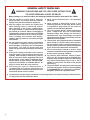
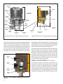
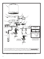
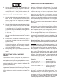
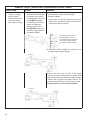
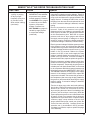
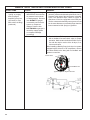
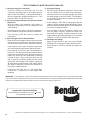
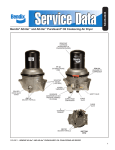
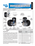
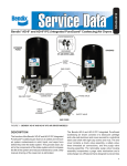
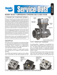
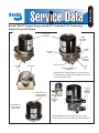
SD-08-2414
®
Bendix® AD-IP® Integral Purge and AD-IP® PuraGuard® Oil Coalescing
Integral Purge Air Dryers
DESICCANT
CARTRIDGE
CABLE
MOUNTING
BRACKET
CONTROL
PORT
MOUNTING
CABLE
LOWER
MOUNTING
BRACKET
DELIVERY
PORT
SAFETY VALVE
DISCHARGE
HEATER & THERMOSTAT
CONNECTOR
SUPPLY
PORT
Bendix® AD-IP® integral purge air dryer with the
PuraGuard® oil coalescing cartridge and the new
cable mounting bracket.
OLD STYLE
SADDLE
MOUNTING
BRACKET
PURAGUARD ® OIL
COALESCING AIR
DRYER MEDALLION
EXTENDED
PURGE
PORT
PURAGUARD OIL
COALESCING AIR
DRYER LABEL
Standard Bendix AD-IP integral purge air dryer
shown with the old style saddle mounting bracket.
FIGURE 1 - BENDIX® AD-IP® INTEGRAL PURGE AIR DRYERS
1
GENERAL SAFETY GUIDELINES
WARNING! PLEASE READ AND FOLLOW THESE INSTRUCTIONS
TO AVOID PERSONAL INJURY OR DEATH:
When working on or around a vehicle, the following guidelines should be observed AT ALL TIMES:
▲ Park the vehicle on a level surface, apply the
parking brakes and always block the wheels.
Always wear personal protection equipment.
▲ Stop the engine and remove the ignition key
when working under or around the vehicle.
When working in the engine compartment,
the engine should be shut off and the ignition
key should be removed. Where circumstances
require that the engine be in operation, EXTREME
CAUTION should be used to prevent personal
injury resulting from contact with moving,
rotating, leaking, heated or electrically-charged
components.
▲ Do not attempt to install, remove, disassemble
or assemble a component until you have read,
and thoroughly understand, the recommended
procedures. Use only the proper tools and
observe all precautions pertaining to use of those
tools.
▲ If the work is being performed on the vehicle’s
air brake system, or any auxiliary pressurized air
systems, make certain to drain the air pressure
from all reservoirs before beginning ANY work
on the vehicle. If the vehicle is equipped with a
Bendix® AD-IS® air dryer system, a Bendix® DRM™
dryer reservoir module, or a Bendix® AD-9si™ air
dryer, be sure to drain the purge reservoir.
▲ F o l l o w i n g t h e v e h i c l e m a n u f a c t u r e r ’s
recommended procedures, deactivate the
electrical system in a manner that safely removes
all electrical power from the vehicle.
▲ Never exceed manufacturer’s recommended
pressures.
▲ Never connect or disconnect a hose or line
containing pressure; it may whip. Never remove
a component or plug unless you are certain all
system pressure has been depleted.
▲ Use only genuine Bendix ® brand replacement
parts, components and kits. Replacement
hardware, tubing, hose, fittings, etc. must be of
equivalent size, type and strength as original
equipment and be designed specifically for such
applications and systems.
▲ Components with stripped threads or damaged
parts should be replaced rather than repaired.
Do not attempt repairs requiring machining or
welding unless specifically stated and approved
by the vehicle and component manufacturer.
▲ Prior to returning the vehicle to service, make
certain all components and systems are restored
to their proper operating condition.
▲ For vehicles with Automatic Traction Control
(ATC), the ATC function must be disabled (ATC
indicator lamp should be ON) prior to performing
any vehicle maintenance where one or more
wheels on a drive axle are lifted off the ground
and moving.
▲ The power MUST be temporarily disconnected
from the radar sensor whenever any tests USING
A DYNAMOMETER are conducted on a Bendix®
Wingman® Advanced™-equipped vehicle.
▲ You should consult the vehicle manufacturer's operating and service manuals, and any related literature,
in conjunction with the Guidelines above.
2
DESCRIPTION
IMPORTANT
The function of the Bendix® AD-IP® integral purge air
dryer — and the Bendix® AD-IP® integral purge air dryer
with PuraGuard® oil coalescing — is to collect and remove
air system contaminants in solid, liquid and aerosol form,
before they enter the brake system. They provide clean, dry
air to the components of the brake system which increases
the life of the system and reduces maintenance costs. Daily
manual draining of the reservoirs is eliminated.
When servicing, note that standard Bendix AD-IP air
dryers, or air dryer cartridges, may be serviced with
PuraGuard® oil coalescing air dryer or cartridges, however,
PuraGuard (PG) oil coalescing air dryer or cartridges must
only be serviced with like replacements.
The AD-IP and AD-IP PuraGuard oil coalescing air dryers
consist of a desiccant cartridge secured to a die cast
aluminum end cover with a single, central bolt. The end
cover contains a check valve assembly, safety valve,
heater and thermostat assembly, three pipe thread air
connections, optional extended purge port (plugged), and
the purge valve assembly. The removable purge valve
assembly incorporates the purge valve mechanism and
a turbo charger cut-off feature that is designed to prevent
loss of engine turbo-boost pressure during the purge cycle
of the air dryer. For ease of serviceability, all replaceable
assemblies can be replaced without removing the air dryer
from its mounting on the vehicle.
The AD-IP air dryer has three female pipe thread air
connections identified as follows:
Air Connection
Function/Connection
CON 4 ............................Control Port (purge valve control
& turbo cut-off).
Sensitive downstream components such as automated
manual transmissions, diesel exhaust emission systems,
etc. can be damaged due to excessive oil levels. Therefore,
always replace a PG cartridge with a Bendix PG cartridge.
SUP 11............................Supply Port (air in).
DEL 2.............................Delivery Port (air out).
(Not Identified)................Extended Purge Port
The AD-IP PuraGuard oil coalescing air dryer has an
identical appearance to the standard AD-IP air dryer, but
contains a coalescing media at the inlet of the desiccant
bed. The coalescing media provides a higher level of
oil removal over the standard AD-IP air dryer. The ADIP PuraGuard oil coalescing air dryer has all the same
functions of the standard AD-IP air dryer and is used where
lower oil concentration levels are required. The AD-IP
PuraGuard oil coalescing air dryer can be identified by the
PuraGuard oil coalescing label shown in Figure 1 located
on the air dryer cartridge.
Early Bendix AD-IP air dryers included a “Drop In”
configuration for air systems that use either the Holset ®
(Cummins®) Type E or QE air compressor. For information
pertaining to this configuration see the Bendix AD-IP Air
Dryer Troubleshooting Chart at the end of the manual.
3
Note 1:
The Bendix® AD-IP® air dryer and reservoir
system purge piston has a purge control
channel drain. This allows any condensation
in this area to flow past a diaphragm in the
top of the purge piston and out through a
channel in the middle of the central bolt of
the purge assembly to be drained. During
the purge cycle this drain is closed.
OIL
SEPARATOR
DESICCANT
BED
PURGE
ORIFICE
PURGE
VOLUME
CONTROL
PORT
PURGE
CONTROL
LINE
SUPPLY
PORT
DELIVERY
CHECK VALVE
GOVERNOR
DISCHARGE
PORT
COMPRESSOR
ENGINE
TURBO
TURBO
CUT-OFF VALVE
EXHAUST
PURGE
VALVE
FIGURE 2 - BENDIX® AD-IP® INTEGRAL PURGE AIR DRYER CHARGE CYCLE
OPERATION
GENERAL
Note: Unless otherwise stated in this manual, the Bendix®
AD-IP® air dryer refers to both the standard and Bendix®
AD-IP® PuraGuard® oil coalescing air dryer. The AD-IP air
dryer alternates between two operational modes or “cycles”
during operation: the Charge Cycle and the Purge Cycle.
The following description of operation is separated into
these “cycles” of operation.
CHARGE CYCLE (Refer to Figure 2)
When the compressor is loaded (compressing air)
compressed air — along with oil, oil vapor, water and water
vapor — flows through the compressor discharge line to the
supply port of the air dryer body.
As air travels through the end cover assembly, its direction
of flow changes several times, reducing the temperature,
causing contaminants to condense and drop to the bottom
or sump of the air dryer end cover.
After exiting the end cover, the air flows into the desiccant
4
cartridge. Once in the desiccant cartridge the air first flows
through an oil separator, located between the outer and
inner shells of the cartridge. The separator removes water
in liquid form as well as liquid oil and solid contaminants.
Air, along with the remaining water vapor, is further cooled
as it exits the oil separator and continues to flow upward
between the outer and inner shells. Upon reaching the top
of the cartridge the air reverses its direction of flow and
enters the desiccant drying bed. Air flowing down through
the column of desiccant becomes progressively drier as
water vapor adheres to the desiccant material in a process
known as “ADSORPTION.” The desiccant cartridge using
the adsorption process typically removes most of the water
vapor from the pressurized air.
Dry air exits the bottom of the desiccant cartridge and flows
through the center of the bolt used to secure the cartridge
to the end cover. Air flows down the center of the desiccant
cartridge bolt, through a cross drilled passage and exits
the air dryer delivery port through the delivery check valve.
OIL
SEPARATOR
DESICCANT
BED
PURGE
ORIFICE
PURGE
CONTROL
LINE
PURGE
VOLUME
CONTROL
PORT
SUPPLY
PORT
DELIVERY
CHECK VALVE
GOVERNOR
DISCHARGE
PORT
COMPRESSOR
ENGINE
TURBO
TURBO
CUT-OFF VALVE
EXHAUST
PURGE
VALVE
FIGURE 3 - BENDIX® AD-IP® INTEGRAL PURGE AIR DRYER PURGE CYCLE
Note: the early end cover designs incorporated a vertical
delivery check valve while the newer versions have a
horizontal check valve. Both have the same function, but
the components are not interchangeable. See Figure 4.
A small amount of the air flowing through the center of the
desiccant cartridge bolt flows out the cross drilled purge
orifice and into the purge volume, for regenerating the
desiccant. The air dryer will remain in the charge cycle
until the air brake system pressure builds to the governor
cut-out setting.
PURGE CYCLE (Refer to Figure 3)
As air brake system pressure reaches the cut-out setting
of the governor, the governor unloads the compressor (air
compression is stopped) and the purge cycle of the air
dryer begins. When the governor unloads the compressor,
it pressurizes the compressor unloader mechanism and the
line connecting the governor unloader port to the Bendix®
AD-IP® air dryer end cover control port. The purge piston
moves in response to air pressure causing the purge
valve to open to the atmosphere and the turbo cut-off
valve to close off the supply of air from the compressor
(this will be further discussed in the Turbo Cut-off Feature
section). Water and contaminants in the end cover sump
are expelled immediately when the purge valve opens.
Also, air which was flowing through the desiccant cartridge
changes direction and begins to flow toward the open purge
valve. Liquid oil and solid contaminants collected by the oil
separator are removed by air flowing from the purge volume
through the desiccant drying bed to the open purge valve.
The desiccant cartridge decompression lasts only a few
seconds and is evidenced by an audible burst of air at the
AD-IP air dryer exhaust. No purging of air should occur
after 30 seconds.
5
DESICCANT
BED
SPRING
OIL
SEPARATOR
DESICCANT
CARTRIDGE
PURGE
ORIFICE
PIPE PLUG
PURGE
VOLUME
CONTROL
PORT
CHECK
VALVE
(BLACK)
SUPPLY
PORT
DELIVERY
PORT
TURBO
CUT-OFF
VALVE
PURGE
VALVE
CARTRIDGE
BOLT
DELIVERY
PORT
Old Style End Cover -Vertical Delivery Check Valve
CARTRIDGE
BOLT
O-RING
CHECK VALVE
(WHITE)
New Style End Cover - Horizontal Delivery Check Valve
FIGURE 4 - BENDIX® AD-IP® AIR DRYER SECTIONAL VIEW
The actual reactivation of the desiccant drying bed begins
as dry air flows from the purge volume through the purge
orifice in the desiccant cartridge bolt, then through the
center of the bolt and into the desiccant bed. Pressurized
air from the purge volume expands after passing through
the purge orifice; its pressure is lowered and its volume
increased. The flow of dry air through the drying bed
CONTROL
PORT
reactivates the desiccant material by removing the water
vapor adhering to it. Generally 30 seconds are required for
the entire purge volume of a standard Bendix® AD-IP® air
dryer to flow through the desiccant drying bed.
The delivery check valve assembly prevents air pressure in
the brake system from returning to the air dryer during the
purge cycle. After the 30 second purge cycle is complete
the desiccant has been reactivated or dried. The air dryer
is ready for the next charge cycle to begin. However the
purge valve will remain open and will not close until air
brake system pressure is reduced and the governor signals
the compressor to charge the system.
TURBO CUT-OFF FEATURE (Refer to Figure 5)
SUPPLY
PORT
TURBO
CUT-OFF
VALVE
PURGE
VALVE
FIGURE 5 - AD-IP® INTEGRAL PURGE AIR DRYER TURBO
CUT-OFF
6
The primary function of the turbo cut-off valve is to
prevent loss of engine turbocharger air pressure through
the AD-IP air dryer in systems where the compressor
intake is connected to the engine turbocharger. The turbo
cut-off valve also removes the “puffing” of air out the open
purge exhaust when a naturally aspirated, single cylinder
compressor, equipped with an inlet check valve, is in use.
3 O-RING
GROOVES
2 O-RING
GROOVES
PURGE VALVE
HOUSING
STANDARD
PURGE VALVE
DLU
PURGE VALVE
FIGURE 6 - BENDIX® AD-IP® AND AD-IP DLU AIR DRYER PURGE VALVES
At the onset of the purge cycle, the downward travel of
the purge piston is stopped when the turbo cut-off valve
(tapered portion of purge piston) contacts its mating metal
seat in the purge valve housing. With the turbo cut-off valve
seated (closed position), air in the compressor discharge
line and Bendix® AD-IP® air dryer inlet port cannot enter
the air dryer. In this manner the turbo cut-off effectively
maintains turbocharger boost pressure to the engine.
DISCHARGE LINE UNLOADER (Refer to Figure 6)
The Bendix AD-IP air dryers are available as a standard air
dryer and as a Discharge Line Unloader (DLU-style) . The
functions of these air dryers (Standard vs. DLU) and their
internal components are different. The standard air dryer
cuts off the supply air from compressor to the air dryer
when the compressor is in the unloaded mode, while the
DLU air dryer utilizes a purge valve to bleed off the excess
air instead of unloading the compressor. Externally the
standard and DLU versions of each air dryer configuration
are identical in appearance; however the DLU-style air
dryer often has a silencer on the exhaust port.
PREVENTIVE MAINTENANCE
Important: Review the warranty policy before performing
any intrusive maintenance procedures. An extended
warranty may be voided if intrusive maintenance is
performed during this period. Note: It is acceptable for
the purge valve to be maintained as necessary, i.e., the
installation of a purge valve maintenance kit, without
voiding the warranty.
Because no two vehicles operate under identical
conditions, maintenance and maintenance intervals will
vary. Experience is a valuable guide in determining the
best maintenance interval for any one particular operation.
For Bendix AD-IP air dryers: Preventive Maintenance
is as easy as 1-2-3
Adhering to a preventive maintenance schedule is crucial
to keeping a vehicle’s air system clean and ensuring
superior performance of all components that utilize
system air— such as brakes, emissions equipment and
automated manual transmissions. Depending on vocation,
Bendix recommends a 1, 2 or 3-year air dryer cartridge
replacement on vehicles equipped with a Bendix ®
compressor.
For severe service applications — such as residential
refuse trucks or school buses — the air dryer cartridge
should be replaced every year or 100,000 miles; for pickup and delivery operations, or for double- and triple-trailer
line haul trucks, every two years or 200,000 miles is the
recommendation. Line-haul operations using a single trailer
should swap the filter out every three (3) years or 300,000
miles. The recommended intervals for trucks equipped with
non-Bendix compressors are 6 months (50,000 miles),
one year (100,000 miles) and two years (200,000 miles),
respectively.
More frequent intervals may be required depending
on a vehicle’s age, its compressor condition, use of a
non-Bendix compressor, the operating environment, the
vehicle’s vocation, and its usage. In conjunction with these
guidelines, fleets can determine the functionality of their
filters by checking for moisture in the air brake system
monthly. If moisture is present, the air dryer cartridge may
require replacement. Reference the Bendix Service Data
Sheet of the specific air dryer for additional information.
(Recommended intervals for trucks equipped with nonBendix compressors are 6 months (50,000 miles), one
year (100,000 miles) and two years (200,000 miles),
respectively.)
7
Notes:
1. Visually check for physical damage to the air dryer
such as chaffed or broken air and electrical lines and
broken or missing parts.
2. Check mounting bolts for tightness. Re-torque to
270–385 in-lbs.
3. Perform the Operation & Leakage Tests listed in this
publication.
This air dryer is intended to remove moisture and other
contaminants normally found in the air brake system.
Do not inject alcohol, anti-freeze, or other de-icing
substances into or upstream of the air dryer. Alcohol
is removed by the dryer, but reduces the effectiveness
of the device to dry air. Use of other substances can
damage the air dryer and may void the warranty.
4. Check the operation of the end cover heater and
thermostat assembly during cold weather operation as
follows:
A. Electric Power to the Dryer
With the ignition or engine kill switch in the ON
position, check for voltage to the heater and
thermostat assembly using a voltmeter or test
light. Unplug the electrical connector at the air
dryer and place the test leads on each of the pins
of the connector with the locking latch. If there is
no voltage, look for a blown fuse, broken wires, or
corrosion in the vehicle wiring harness. Check to
see if a good ground path exists.
B. Thermostat and Heater Operation
Note: These tests are not required except in cold
weather operation.
Turn off the ignition switch and cool the thermostat
and heater assembly to below 35° F. Using an
ohmmeter, check the resistance between the
electrical pins in the air dryer connector half. The
resistance should be 1.5 to 3.0 ohms for the 12 volt
heater assembly and 6.0 to 9.0 ohms for the 24 volt
heater assembly.
Warm the thermostat and heater assembly to
over 90° F. and again check the resistance. The
resistance should exceed 1000 ohms. If the
resistance values obtained are within the stated
limits, the thermostat and heater assembly is
operating properly. If the resistance values obtained
are outside the stated limits, replace the heater and
thermostat assembly.
OPERATION & LEAKAGE TESTS
1. Install a pressure gauge in the #1 reservoir. Check
all lines and fittings leading to and from the air dryer
for leakage and integrity. Test the delivery port check
valve assembly by building the air system to governor
cut-out and observing a test air gauge installed in the
#1 reservoir. Note the pressure on the air gauge after
governor cut-out pressure is reached, a rapid loss of
pressure could indicate a failed delivery port check
valve. This can be confirmed by shutting the engine off,
draining the air brake system pressure to a point below
governor cut-in (typically < 95 psi). Make sure the dryer
has completed the purge cycle (wait 30 seconds after
governor cut-out) and determine if there is any air flow
out of the air dryer purge valve. If air flow is detected
at the purge valve, the air dryer delivery check valve
should be serviced. Remove the test gauge before
returning the vehicle to service.
2. Check for excessive leakage around the purge valve.
With the compressor in loaded mode (compressing
air), apply a soap solution to the purge valve exhaust
port and observe that leakage does not exceed a
one (1) inch bubble in one (1) second. If the leakage
exceeds the maximum specified, repair the purge valve
assembly.
3. Make sure all reservoir drain cocks are closed. Build
up system pressure to governor cut-out and note that
Bendix® AD-IP® air dryer purges with an audible escape
of air. Apply and release the service brakes to reduce
system air pressure to governor cut-in. Note that the
system once again builds to full pressure and is
followed by an AD-IP air dryer purge.
REBUILDING THE BENDIX ® AD-IP ® AIR
DRYER
GENERAL
If, after completing the routine operation and leakage tests,
it has been determined that one or more components of
the air dryer requires replacement or maintenance, refer to
the Bendix Quick Reference Catalog (BW1114), available
on www.bendix.com, for the latest maintenance kits and
service parts.
When rebuilding or replacing components of the air dryer
use only genuine Bendix® service parts.
BENDIX AD-IP AIR DRYER REMOVAL
This air dryer removal process is presented in the event
it becomes necessary to replace the entire air dryer.
Normal service and parts replacement does not require
removal of the air dryer from the vehicle.
1. Park the vehicle on a level surface and prevent
movement by means other than the brakes.
8
Maintenance Kits
Description
Piece
Number
Cartridge Bolt Kit
109498
Desiccant Cartridge Service New
065624
Desiccant Cartridge Remanufactured
109493X
Bendix® PuraGuard® Coalescing Cartridge Kit Service New
065624PG
PuraGuard Coalescing Cartridge Kit Reman Exchange
109493PGX
Delivery Check Valve Kit
109494
Exhaust Cover Kit
HEATER &
THERMOSTAT
CONNECTOR
AD-IP® AIR
DRYER END
COVER
5011327
Extended Purge Kit 3/8" U-Bolt; 90in3 Reservoir
5012561N
Extended Purge Kit 3/8" U-Bolt; 288in3 Reservoir
5008972N
Extended Purge Kit 1/2" U-Bolt; 90in3 Reservoir
5005309N
12 Volt Heater & Thermostat Kit
LOCKING LATCH
(MUST BE INSERTED UNTIL IT
SNAPS OVER THE MATING CONNECTOR
ON AD-IP® AIR DRYER
109495
24 Volt Heater & Thermostat Kit
109496
Mounting Bracket Kit
5001247
Silencer Kit
K021189
Wiring Harness & Splicing Kit
109871N
SIDE VIEW
TOP VIEW
WEATHERPROOF
ACCORDIAN
SEAL
Purge Valve Maintenance Kits
Purge Valve
Assembly Type
Purge Valve Assembly
Kit for climate conditions
above -40°C (-40°F)
Arctic Purge Valve
Assembly Kit for climate
conditions between
-40°C to -50°C
(-40°F to -58°F)
Configuration /
Installation
Piece
Number
Bendix® AD-IP® Air Dryer
K022105
Bendix AD-IP
EverFlow® Air Dryer
Module
AD-IP Drop-In
Air Dryer
K031560
AD-IP Air Dryer
K031559
AD-IP EverFlow
Air Dryer Module
AD-IP Drop-In Air Dryer
K031561
®
®
Purge Valve Assembly
Kit for climate conditions
above -40°C (-40°F)
Bendix AD-IP Air Dryer
Discharge Line Unloader
K031562
Arctic Purge Valve
Assembly Kit for climate
conditions between -40°C
to -50°C (-40°F to -58°F)
AD-IP Air Dryer Discharge
Line Unloader
K031563
®
®
2.Drain all reservoirs to 0 psi. Compressor discharge
line may still contain residual pressure.
3. Identify and disconnect the three air lines from the end
cover and note the position of end cover ports relative
to the vehicle.
A two lead wire harness with attached weather resistant
connector is available as a service part. One of the two
leads is connected to the engine “kill switch” or ignition while
the other must be connected to a good vehicle ground. A
fuse is installed in the lead carrying vehicle power; install
a 10 amp fuse for the 12 volt heater and a 5 amp fuse for
the 24 volt heater.
Use 14 AWG wire if it is necessary to lengthen the wire
harness leads. Make certain all splices are weatherproofed.
Tie wrap or support all electrical wires leading to the AD-IP
air dryer.
FIGURE 7 - BENDIX® AD-IP® AIR DRYER HEATER AND
THERMOSTAT CONNECTOR
4. Unplug the vehicle wiring harness from the heater
and thermostat assembly connector on the end cover
assembly.
5. Remove the four bolts that secure both the upper and
lower mounting brackets to the vehicle, and remove
the air dryer from the vehicle.
9
11
1
4
5
3
19
6
22
21
20
9
23 24 25
SLIDE INSTALLATION
RING INTO PURGE
BORE
16
2
17
18
8
12
13
10
15
STANDARD
STYLE PURGE
VALVE
7
*16
18
14
15
APPLY LUBRICANT
TO INSIDE
SURFACE
INSTALLATION RING (NOTE THE ORIENTATION
OF THE BEVEL OF THE RING
BEFORE INSTALLATION.)
DISCHARGE LINE
UNLOADED (DLU)
STYLE PURGE VALVE
14
*Most OE installed Bendix® AD-IP® air dryers manufactured after January 1, 2014 will not be equipped with
a purge valve installation ring (16). The function of the installation ring has been incorporated into the air
dryer lower housing. Be sure to replace the installation ring if it was removed during servicing procedures.
FIGURE 8 - BENDIX® AD-IP® AIR DRYER INTERNAL COMPONENTS – HORIZONTAL DELIVERY CHECK VALVE
10
Item
Description
Qty.
Reference Figure 8
1
5/16” Cap Screw
1
2
O-ring
1
3
5/16” Sleeve Nut
1
4
Mounting Strap
1
5
Saddle Bracket
1
6
End Cover
1
7
3/8” Cap Screw
2
8
3/8” Lock Washer
2
9
Lower Mounting Bracket
1
10
Cartridge Bolt
1
11
Desiccant Cartridge
1
12
O-ring
1
13
O-ring
1
14
Retaining Ring
1
15
Purge Valve Cartridge Assembly
1
*16
Installation Ring
1
17
O-ring
1
18
O-ring
1
19
O-ring
1
20
Retaining Ring
1
21
Heater & Thermostat Assembly
1
22
Safety Valve Assembly
1
23
Delivery Check Valve Plug
1
24
Spring
1
25
Check Valve Body (white)
1
Reference Figure 9
26
Perforated Plate
1
27
Check Ring Spring
1
28
Check Valve
1
29
O-ring
1
30
Retaining Ring
1
Reference Figure 10
31
Upper Bracket
1
32
Cable Assembly
1
33
Isolator
2
34
Locknut
1
35
Washer
1
PIPE PLUG
AIR DRYER
END COVER
DELIVERY PORT
(TO SUPPLY
RESERVOIR)
28
26
DELIVERY PORT
(TO SUPPLY
RESERVOIR)
CONTROL PORT
(FROM GOVERNOR
UNLOADER PORT)
29
SUPPLY PORT
(FROM
COMPRESSOR)
27
30
Old Style Bendix® AD-IP® End Cover Vertical Delivery Check Valve
FIGURE 9 - BENDIX® AD-IP® AIR DRYER INTERNAL COMPONENTS –
VERTICAL DELIVERY CHECK VALVE
11
INSTALL CABLE
ASSEMBLY IN THIS AREA
32
33
DELIVERY
PORT
LOWER BRACKET
MOUNTING
HOLES
35
34
31
8
INSERT CABLE
ASSEMBLY IN UPPER
BRACKET WING HOLE AS
SHOWN
9
7
FIGURE 10 - BENDIX® AD-IP® AIR DRYER CABLE BRACKET INSTALLATION
There are two types of upper mounting brackets; saddle
type (shown in Figure 8), and cable type (shown in Figure
10). Refer to the appropriate figure for the type of air dryer
being serviced.
6. Saddle Bracket: Mark the relationship of the saddle
bracket (5) to the end cover assembly (6). Remove
the 5/16” cap screw (1) and sleeve nut (3) securing
the upper mounting strap (4) to the saddle bracket (5).
Earlier models used a washer and nut in place of the
sleeve nut (3). Remove the upper mounting strap (4)
from the end cover assembly (6). Refer to Figure 8.
DISASSEMBLY
The following disassembly and assembly procedure is
presented for reference purposes and presupposes that
a major rebuild of the Bendix® AD-IP® air dryer is being
undertaken. The replacement parts and maintenance kits
available generally do not require full disassembly. The
instructions provided with these parts and kits should be
followed in lieu of the instructions presented here. Refer
to Figures 8 and 9 during disassembly.
Cable Bracket: Mark the relationship of the upper
bracket (31) to the air dryer end cover (6). Remove the
locknut (34) and washer (35) from the cable assembly.
Remove the cable assembly (32) from the upper
bracket. Remove the upper bracket (31) and isolators
(33).
While performing service on the AD-IP air dryer, it is
recommended that a clamping device (vise, C-clamp, etc.)
not be used to hold any die cast aluminum component as
damage may result. To hold the end cover, install a pipe
nipple in the supply port and clamp the nipple into a vise.
7. Mark the relationship of the lower bracket (9) to the end
cover assembly (6). Remove the two 3/8” end cover cap
screws (7) and two washers (8) that retain the lower
mounting bracket (9) to the end cover (6).
1. Using an adjustable, or socket wrench, loosen the
desiccant cartridge bolt (10), then separate the
desiccant cartridge (11) from the end cover (6). Pull
the desiccant cartridge bolt out of the end cover (6).
12
ASSEMBLY
Disassembly of the desiccant cartridge assembly
should not be attempted! Detail parts for the cartridge
are not available and the cartridge contains a 150#
spring which can not be mechanically caged.
For purge valve assembly instructions refer to the
instruction sheet included in the kit. A listing of maintenance
kits is included in this document.
1. Complete the purge valve installation per the installation
instructions provided in the service kit.
2. Remove both o-rings (12 & 13) from the desiccant
cartridge bolt.
2. Using a 9/16” wrench, install the safety valve assembly
(22) into the end cover (6).
3. Remove the retaining ring (14) that secures the purge
valve assembly (15) in the end cover (6).
3. Vertical check valve models: See Figure 9. Install
the o-ring (29) on the check valve body (28) and push
the o-ring down, over the 3 guide lands until it is in the
o-ring groove of the check valve body (28). Install the
check valve spring (27) on the check valve body so that
the small coils of the spring slip over the check valve
body. Install the assembled check valve body, o-ring,
and spring (27, 28 & 29) in the end cover (6) so that
the o-ring rests on its seat in the end cover (6) and the
spring is visible. Install the perforated plate (26), in the
end cover (6) and secure the check valve assembly
using the retaining ring (30). Make certain the retaining
ring is fully seated in its groove in the end cover (6).
4. Vertical check valve models: Remove the retaining
ring (30) that secures the delivery check valve
assembly in the end cover (6). Remove and separate
the perforated plate (26), spring (27), check valve body
(28) and o-ring (29).
5. Horizontal check valve models: Remove delivery
check valve plug (23) that secures the check valve
assembly in the end cover (6). Remove the spring
(24), check valve (25) and o-ring (2).
6. Remove the retaining ring (20) that secures the heater
and thermostat assembly (21) in the end cover (6).
Gently pull the heater and thermostat (21) out of the
end cover (6) and remove the o-ring (19).
7. Using a 9/16” wrench, remove the safety valve
assembly (22) from the end cover (6).
CLEANING & INSPECTION
1. Using mineral spirits or an equivalent solvent, clean
and thoroughly dry all metal parts except the desiccant
cartridge.
2. Inspect the interior and exterior of all metal parts that
will be reused for severe corrosion, pitting and cracks.
Superficial corrosion and/or pitting on the exterior
portion of the end cover is acceptable.
3. Inspect the bores of both the end cover and the purge
valve housing for deep scuffing or gouges.
4. Make certain that all purge valve housing and end cover
passages are open and free of obstructions.
5. Inspect the pipe threads in the end cover. Make certain
they are clean and free of thread sealant.
6. Make certain that the purge orifice in the cartridge bolt
is open and free of obstructions.
7. Inspect all air line fittings for corrosion. Clean all old
thread sealant from the pipe threads.
8. All o-rings removed should be discarded and replaced
with new o-rings provided in appropriate kit(s).
4. Horizontal check valve models: Install o-ring (2) onto
check valve (25). Place the check valve in the delivery
check valve port of the end cover (6). Install the spring
(24) over the delivery check valve (36) and secure with
the delivery check valve plug (23).
5. Install the o-ring (19) on the heater and thermostat
assembly (21). After making certain the sponge rubber
cushion is positioned between the connector body and
thermostat, gently push the heater and thermostat
assembly (21) into the end cover (6), making certain
the heating element enters the small diameter bore in
the larger heater and thermostat bore in the end cover
(6). Secure the heater and thermostat assembly in the
body using the retaining ring (20). Make certain the
retaining ring is fully seated in its groove in the end
cover (6).
6. Lubricate the o-rings (12 & 13) and install them on
the desiccant cartridge bolt (10) and using a twisting
motion, insert the assembled desiccant cartridge bolt
in the end cover (6).
7. Install the desiccant cartridge (11) on the end cover
(6) making certain the cartridge is properly seated and
flush on the end cover.
Note: It may be necessary to rotate the cartridge slightly
until the anti-rotation lugs are properly aligned and allow
the cartridge to rest flush against the end cover.
13
VEHICLE APPLICATION REQUIREMENTS
8. Using an adjustable wrench or a socket, tighten the
desiccant cartridge bolt (10), to secure the desiccant
cartridge (11) to the end cover (6). Torque the desiccant
cartridge bolt to 65–75 ft-lbs (40 ft-lbs minimum). Do
not over torque.
BENDIX® AD-IP® AIR DRYER INSTALLATION
1. Using the relationship marks made during step 7 of the
Bendix® AD-IP® Air Dryer Removal Procedure, install
the lower mounting bracket (9) on the end cover (6) and
secure it using the two 3/8” cap screws and washers
(7 & 8). Torque the cap screws to 300–360 in-lbs.
2. Using the relationship marks made during step 6 of the
AD-IP Air Dryer Removal Procedure, install the saddle
bracket (5) and mounting strap (4) on the end cover
(6), and using the 5/16” cap screw (1) and sleeve nut
(3) secure the strap to the saddle bracket. Tighten the
5/16” nut on the upper mounting bracket. Torque to
60-100 in-lbs.
3. Install the air dryer on the vehicle using the four
bolts that secure both the upper and lower mounting
brackets.
4. Reconnect the three airlines to the proper ports on
the end cover (identified during step 3 of the AD-IP Air
Dryer Removal).
5. Reconnect the vehicle wiring harness to the Bendix
AD-IP air dryer heater and thermostat assembly
connector by plugging it into the air dryer connector
until its lock tab snaps in place.
6. Before placing vehicle back into service, perform the
Operation and Leakage Tests stated elsewhere in this
manual.
RETROFITTING THE AD-IP AIR DRYER
GENERAL
The following retrofit instructions are presented for
reference purposes only since Bendix aftermarket retrofit
and replacement air dryers are packaged with the most upto-date installation instructions. The instructions packaged
with the Bendix AD-IP air dryer should be followed in lieu
of those presented here.
The preceding portion of this manual deals with “in-service”
repair and/or replacement of the AD-IP air dryer. The portion
of the manual that follows is concerned with installing an
AD-IP air dryer on a vehicle not previously equipped with
one.
14
The basic application requirements presented here
apply to a standard air dryer installation. The majority
of highway vehicles in use today will meet these basic
requirements however, some may not. Examples of
vehicles that may not meet the requirements include,
refuse trucks, city coaches, bulk trailer unloading
operations and other high air consumption systems.
While the Bendix AD-IP air dryer can be used on these
vehicles, the standard installation procedure presented
in this manual may require modification to ensure proper
operation and service life. Consult your local authorized
Bendix® parts outlet or sales representative for additional
information.
Charge Cycle Time — The AD-IP air dryer is designed to
provide clean, dry air for the brake system. When a vehicle’s
air system is used to operate non-brake air accessories it is
necessary to determine that, during normal daily operation
the compressor should recover from governor “cut-in” to
governor “cut-out” (usually 100 psi to 120 psi) in 90 seconds
or less at engine RPMs normal to the vehicle vocation. If
the recovery time consistently exceeds this limit, it may be
necessary to “bypass” the air accessory responsible for the
high air usage. Consult your local authorized Bendix parts
outlet or sales representative for additional information.
Purge Cycle Time — During normal vehicle operation, the
air compressor must remain unloaded for a minimum of 30
seconds. This minimum purge time is required to ensure
complete regeneration of the desiccant material. If the
purge time is occasionally shorter than the times specified,
no permanent ill effect should be expected, however, if
the purge time is consistently less than the minimum,
an accessory bypass system must be installed. Contact
the nearest authorized Bendix parts outlet or Bendix
representative for additional information. Note: Reservoir
Volume - Total vehicle reservoir volume can impact the
Charge and Purge Cycle time. The chart below can be
used as a guide in determining if additional help is required.
Total Vehicle Reservoir
Volume
Requirement
Less than 9,000 cu. in. .........................Standard AD-IP Air Dryer
9,000 - 12,500 cu. in. ...........................Extended Purge AD-IP Air
Dryer
Greater than 12,500 cu. in. ............. Contact Bendix Rep. or
Bendix Engineering
Air Compressor Size — Although the AD-IP air dryer can
be used in conjunction with larger compressors, it was
designed primarily for units rated for up to 30 CFM. It is
recommended that when using the AD-IP air dryer with a
compressor which has a rated displacement exceeding
30 CFM that an authorized Bendix parts outlet or Bendix
marketing representative be contacted for assistance.
VEHICLE PREPARATION
1. Park the vehicle on a level surface and prevent
movement by means other than the brakes.
2. Drain all reservoirs to 0 psi.
LOCATING BENDIX® AD-IP® AIR DRYER ON THE
VEHICLE
1.The Bendix ® AD-IP ® air dryer must be mounted
vertically (purge exhaust toward road surface) outside
the engine compartment in an area of air flow while
the vehicle is in motion. The AD-IP air dryer must not
be exposed to direct wheel splash. If the air dryer is
located directly behind the axle, a mud flap is required.
2. Maintain a minimum clearance of 12” between the
air dryer and any potential heat source (e.g. vehicle
exhaust). If this is not feasible, a heat shield must be
used.
2. Saddle Bracket: Assemble the mounting strap (4) and
saddle bracket (5) as illustrated, by utilizing the 5/16”
cap screw (1) and sleeve nut (3) provided. Place the
upper bracket strap in the end cover channel provided
for it, then install the saddle bracket and secure the
strap to the saddle bracket using the cap screw (1)
and sleeve nut (3) provided. Install, but do not tighten
the cap screw at this time. Orient the strap and saddle
bracket (5) so that it is in a flat plane with the lower
bracket. Torque the 5/16” nut to 60-100 in-lbs to tighten
strap onto the shell.
Cable Bracket: Press the isolators (33) onto the upper
bracket (31) as shown in Figure 10. Place the air dryer
onto the upper bracket (31). Insert the cable assembly
(32) through the wing hole of the upper bracket (31),
around the air dryer and then again through the bracket
(31) on the opposite wing hole. Note: some applications
may require the button end of the cable be placed on
the opposite wing.
When the air dryer is installed, make sure that there
isn’t any interference between the cable ends and the
vehicle mounting bracket. The cable assembly (32)
should be placed in the end cover channel when routed
around the air dryer.
Install the washer (35) and locknut (34) on the threaded
end of the cable assembly (32), adjacent to the upper
bracket wing hole. Tighten the locknut (34) until the
washer (35) makes contact with the upper bracket (31).
Do not torque the locknut (34) at this time.
3. Make certain that adequate clearance from moving
components (e.g. drive shaft, suspension, pitman arm,
etc.) is provided.
4. Locate the air dryer on the vehicle so that a minimum of
1/2” clearance above the air dryer is available to allow
desiccant cartridge removal. A minimum of 8” clearance
below the air dryer is required to allow for desiccant
cartridge bolt removal.
5. When choosing the mounting location for the AD-IP
air dryer, note the discharge line length requirements
stated under the heading Connecting the Air Lines,
elsewhere in this manual.
Important Note: Under normal operating conditions,
the maximum inlet air temperature for the AD-IP air
dryer is 160 degrees Fahrenheit.
6. If possible, locate the AD-IP air dryer so that the purge
exhaust does not expel contaminants on vehicle
components. If this is not feasible, the purge exhaust
may be redirected away from the vehicle by installing
an optional special exhaust cover (piece no. 112609).
The exhaust cover is available as a separate item from
authorized Bendix® parts outlets. A 1” ID hose can be
clamped on this special exhaust cover to allow the
exhaust to be redirected.
MOUNTING THE AD-IP AIR DRYER
(Refer to Figure 8)
1. Install the lower mounting bracket (9) on the AD-IP air
dryer. To accomplish this, it will be necessary to choose
two, of the four available, mounting holes. To determine
which two holes to utilize to attach the lower bracket,
take into consideration the piping connections required
to install the AD-IP air dryer and use those that will best
position the unit for ease of installation. Utilizing the
two cap screws (7) and washers (8), provided with the
AD-IP air dryer retrofit unit, attach the lower mounting
bracket and torque to 300–360 in-lbs.
Note: The bracket mounting holes in the end cover
may not be pre-tapped. In this case the mounting bolt
will self-tap the holes on initial installation.
Orient the cable assembly and upper bracket (31) so
that it is in a flat plane with the lower bracket (9). This
can be accomplished in one of two ways: either off, or
on the vehicle as follows:
Off the vehicle: Place the air dryer assembly on a
flat surface with the mounting brackets (1 & 9) down.
Secure the brackets to the surface with C-clamps then
tighten the cable locknut (34) to 140 in-lbs. Use a
wrench on the hex side of the threaded end to prevent
the cable from twisting.
On the vehicle: Bolt the brackets (1 & 9) to the vehicle
air dryer bracket then tighten the cable locknut (34)
to 140 in-lbs. Use a wrench on the hex side of the
threaded end to prevent the cable from twisting.
3. Components and location used to mount the AD-IP air
dryer on the vehicle must be rigid enough to minimize
air dryer vibration.
4. Mount the air dryer on the vehicle using 3/8” bolts (grade
5 min.) and washers. Torque to 25 ft-lbs (300 in-lbs.)
15
CONNECTING THE AIR LINES
GOVERNOR
PURGE CONTROL
LINE TO CON PORT
AD-IP®
AIR
DRYER
COMPRESSOR DISCHARGE LINE
SUPPLY RES.
DELIVERY LINE
FROM DEL PORT
HEATER &
ON AD-IP® AIR
THERMOSTAT
DRYER
LEAD TO
GROUND
FIGURE 11 - BENDIX® AD-IP® AIR DRYER INSTALLATION
FRAME RAIL
STAR WASHER
1/4” or 3/8”
EYELET
NUT
GROUND
LEAD
WEATHERPROOF
POWER LEAD
SPLICE
14 GAUGE POWER WIRE
FROM VEHICLE
WIRE HARNESS
CONNECTOR
(TO AIR DRYER)
FIGURE 12 - WIRING - REMOTE POWER & LOCAL
GROUND
16
1. Install a purge control air line having a minimum
inside diameter of 3/16 inches between the Bendix®
AD-IP® air dryer end cover control port and an unused
unloader port on the governor. The control line must
be connected directly to the governor and not in series
with automatic drain valves, lubrication systems, etc.
2. The control line should slope downward to the end
cover without forming sharp bends or “dips”.
DISCHARGE
LINE TO SUP
PORT
HEATER &
THERMOSTAT
LEAD TO
IGNITION
SWITCH
FUSE
10 AMP - 12 VOLT
5 AMP - 24 VOLT
PURGE CONTROL LINE
GENERAL:
Refer to Appendix A, Table A for recommended discharge
line lengths and sizes for various vehicle applications and
vocations.
PURGE EXHAUST LINE
1. If it is necessary to direct AD-IP air dryer discharge
contaminants away from vehicle components it will be
necessary to purchase a special exhaust cover for the
AD-IP air dryer (Pc. No. 112609) and install on the unit.
A 1 inch (25.4 mm) I.D. hose can be clamped on the
special AD-IP air dryer exhaust cover.
WIRING THE HEATER & THERMOSTAT (Refer to
FIGURE 7)
1. The air dryer is available with either a 12 or 24 volt
heater which uses 90 watts of power. Determine the
vehicle’s electrical system voltage and make certain
that the air dryer that is to be installed contains the same
voltage heater. The air dryer’s part number can be used
to determine the air dryers heater voltage requirement.
The heater voltage can also be identified by the color
of the heater assembly connector as described in the
table below.
Air Dryer Heater
Voltage
12 Volts
24 Volts
Air Dryer Connector
Identification
White (No other markings)
Gray, or White w/Red Dot
2. A two lead, 24 inch, wire harness with attached weather
resistant connector is needed for the installation of an
AD-IP air dryer. Connect one of the two leads of the
wire harness to the engine kill or ignition switch. The
remaining lead of the wire harness must be connected
to a good vehicle ground (not to the air dryer or its
mounting bracket). A fuse must be installed in the power
carrying wire; install a 10 amp fuse for 12 volt heaters
and a 5 amp fuse for 24 volt heaters.
3. The wire harness—available in the Wire Harness and
Splice Kit from authorized Bendix® parts outlets —is not
included with the service replacement air dryer. When
using this kit, if it becomes necessary to lengthen the
harness, use only 14 gauge wire. When splicing wires,
ensure all wire splices are waterproofed.
4. Tie wrap or support all electrical wires leading to the
Bendix® AD-IP® air dryer at 6–8 inch intervals.
Note: Wires should have sufficient slack and not be
completely taught.
TESTING THE BENDIX® AD-IP® AIR DRYER
Before placing the vehicle in service, perform the following
tests.
1. Close all reservoir drain cocks.
2. Build up system pressure to governor cut-out and note
that the air dryer purges with an audible escape of air.
3. “Fan” the service brakes to reduce system air pressure
to governor cut-in. Note that the system once again
builds to full pressure and is followed by a purge at the
AD-IP air dryer exhaust.
4. It is recommended that the following items be tested
for leakage to ensure that the AD-IP air dryer will not
cycle excessively.
(A)Total air system leakage (See Bendix publication
BW5057 “Air Brake Handbook.”)
(B)Compressor unloader mechanism.
(C)Governor.
(D)Drain cock and safety valve in first (supply)
reservoir.
(E)All air connections leading to and from the first
(supply) reservoir.
(F)Delivery check valve.
17
BENDIX® AD-IP® AIR DRYER TROUBLESHOOTING CHART
SYMPTOMS
CAUSE
REMEDY
1. Air dryer is constantly
“cycling” or purging.
Air dryer purges
frequently (every four
(4) minutes or less
while vehicle is idling).
A. Excessive system leakage.
IMPORTANT: Note whether
air pressure loss is shown
on dash gauge(s). Pressure
loss SHOWN on gauges
is caused by service brake
system or component
leakage. Pressure loss
NOT SHOWN on gauges is
caused by supply system or
component leakage.
A.If leakage IS SHOWN on the gauges, test for
excessive service brake system leakage.
Allowable leakage:
Single vehicle - 1 psi/minute either service reservoir.
Tractor trailer - 3 psi/minute either service reservoir.
Repair and retest as required.
Dash
Gauge
Dash
Gauge
Air pressure loss shown on
the dash gauges: test all
components, fittings and lines
in the service brake system
(from this point downstream).
B.If leakage is NOT SHOWN on gauges test for
excessive supply system leakage.
Remove the drain cock, or valve, in the supply
reservoir (wet tank) and install an air gauge. Build
the system pressure and allow the air dryer to purge.
Observe the air gauge in the supply reservoir. The
pressure drop should not exceed 1 psi per minute.
Perform tests 1 to 6 in the order presented.
18
BENDIX® AD-IP® AIR DRYER TROUBLESHOOTING CHART
SYMPTOMS
CAUSE
REMEDY
1. Air dryer is constantly
“cycling” or purging.
Air dryer purges
frequently (every four
(4) minutes or less
while vehicle is idling)
(continued).
A. Excessive system leakage.
IMPORTANT: Note whether
air pressure loss is shown
on dash gauge(s). Pressure
loss SHOWN on the gauges
is caused by service brake
system or component
leakage. Pressure loss
NOT SHOWN on gauges is
caused by supply system
or component leakage.
(continued)
1.Test fittings, hoses, lines and connections. Apply
soap solution to detect excessive leakage. Tighten or
replace as needed then repeat the air dryer chargepurge cycle and observe the gauge installed in the
supply reservoir. If leakage is within limits, remove
the gauge from the reservoir and replace drain cock
or valve. If excessive leakage is detected, continue
testing.
2.Test the accessories connected to the supply
reservoir. Drain all air pressure from system,
disconnect all air lines leading to accessories (fan
clutch, wipers, air seats, etc.) and plug the reservoir
at the disconnection point. Build the air system
pressure until the air dryer purges and observe
the supply reservoir gauge. If leakage is no longer
excessive, repair or replace the leaking accessory.
If excessive leakage is detected, continue testing.
3.Test for governor leakage. Build the system pressure
to the governor cut-out, turn off the engine and apply
a soap solution to governor exhaust port and around
the cap. Leakage should not exceed a one (1) inch
bubble in five (5) seconds. Reduce the system
pressure to 80 psi, or less, and re-apply the soap
solution. Leakage should not exceed a one (1) inch
bubble in five (5) seconds. If excessive leakage is
detected in either test, repair or replace the governor.
4.Test the compressor unloader leakage. Drain all air
pressure from the system and remove the governor
from the compressor. Temporarily plug the governor
unloader port or air line that mated with, or connected
to, the compressor. Build the air system pressure until
the air dryer purges then IMMEDIATELY SHUT OFF
THE ENGINE. Observe the air gauge in the supply
reservoir. If the leakage is within limits, replace the
compressor unloaders. Re-connect the governor to
the compressor (after removing the plug installed in
the governor) and retest while observing the supply
reservoir gauge. If excessive leakage is detected,
continue testing.
5.Test the air dryer purge valve and outlet (delivery)
check valve. Drain all air pressure from the system.
Remove the control line connection at the air
dryer and plug the end of the air line leading to the
governor (not the air dryer control port). Build the
system pressure to governor cut-out and observe the
air gauge. If little or no pressure drop is observed,
replace the air dryer check valve. If a pressure drop
continues, apply a soap solution to the air dryer
purge exhaust and purge control port (where the
control line was removed). Leakage should not
exceed a one (1) inch bubble in five (5) seconds.
If leakage is excessive, repair or replace the purge
valve assembly.
19
BENDIX® AD-IP® AIR DRYER TROUBLESHOOTING CHART
SYMPTOMS
CAUSE
REMEDY
1. Air dryer is constantly
“cycling” or purging.
Air dryer purges
frequently (every four
(4) minutes, or less,
while vehicle is idling)
(continued).
A. Excessive system leakage.
IMPORTANT: Note whether
air pressure loss is shown
on dash gauge(s). Pressure
loss SHOWN on gauges
is caused by service brake
system or component
leakage. Pressure loss
NOT SHOWN on gauges is
caused by supply system
or component leakage.
(continued)
6.With a gauge installed at the RES port of the
governor, pressure should not drop below the “cut-in”
pressure at the onset of the compressor “unloaded”
cycle. If the pressure drops, check for “kinks” or
restrictions in the line connected to the RES port.
The line connected to the RES port on governor must
be the same diameter or preferably larger than the
lines connected to UNL port(s) on governor.
B. Holset® “E” type compressor. B. Test the Holset® E Compressor unloader system
with a feedback line and check valve for proper
operation. Make certain the Holset ECON is not in
use with the drop-in version of the air dryer, if so,
remove and retest.
When installing a Bendix® Drop-In air dryer in a system
equipped with a Holset E or QE compressor, remove
the Holset ECON valve along with its feedback and
governor control line.
Check Valve
Feedback Line
Typical Drop-In Air Dryer End Cover
20
BENDIX® AD-IP® AIR DRYER TROUBLESHOOTING CHART
SYMPTOMS
CAUSE
REMEDY
2. Water and/or oil in
the supply or service
reservoir.
A. Improper discharge line
length or improper line
material. The maximum air
dryer inlet temperature is
exceeded.
A. Refer to Connecting the Air Lines section as well
as Appendix A, Table A columns 1 & 2 then check
line size and length.
B. Air system charged from an
outside air source (outside
air not passing through air
dryer).
B. If the system has an outside air fill provision, outside
air should pass through the air dryer. This practice
should be minimized.
C. Air dryer not purging (see
Symptom #5).
C. See Symptom #5.
D. Purge (air exhaust) time
D. Check causes and remedies for Symptom #1.
insufficient due to excessive
system leakage (see causes
for Symptom #1).
E. Excessive air usage, duty
cycle too high - Air dryer not
compatible with the vehicle
air system requirement
(Improper air dryer/vehicle
application).
Note: Duty Cycle is the ratio
of time the compressor spends
building air to total engine
running time. Air compressors
are designed to build air
(run “loaded”) up to 25% of
the time. Higher duty cycles
cause conditions that affect
air brake charging system
performance which may
require additional maintenance.
Factors that add to the duty
cycle are: air suspension,
additional air accessories,
use of an undersized
compressor, frequent stops,
excessive leakage from fittings,
connections, lines, chambers or
valves, etc.
E.See Appendix A, Table A, column 1, for the
recommended compressor sizes. If the compressor
is “too small” for the vehicle vocation (for example,
where a vehicle’s vocation has changed or service
conditions exceed the original vehicle or engine OE
spec’s) then upgrade the compressor.
Note: The costs incurred (e.g. installing a larger
capacity compressor, etc.) are not covered under
the original compressor warranty.
Charge Cycle Time - The Bendix® AD-IP® air dryer
is designed to provide clean, dry air for the brake
system. When a vehicle’s air system is used to
operate non-brake air accessories it is necessary
to determine that; during normal, daily operation the
compressor should recover from governor “cut-in”
to governor “cut-out” (usually 100 psi to 120 psi) in
90 seconds or less at engine RPM’s commensurate
with the vehicle vocation. If the recovery time
consistently exceeds this limit, it may be necessary
to “bypass” the air accessory responsible for the
high air usage. An example of where a by-pass
system would be required is when the compressor
is used to pressurize a tank trailer for purposes of
off-loading product. Consult your local authorized
Bendix parts outlet or sales representative for
additional information.
Purge Cycle Time - During normal vehicle operation,
the air compressor must remain unloaded for a
minimum of 30 seconds. This minimum purge
time is required to ensure complete regeneration
of the desiccant material. If the purge time is
consistently less than the minimum, an accessory
by-pass system must be installed. Consult your
local authorized Bendix® parts outlet or sales
representative for additional information.
21
BENDIX® AD-IP® AIR DRYER TROUBLESHOOTING CHART
SYMPTOMS
CAUSE
REMEDY
2. Water and/or oil in
the supply or service
reservoir (continued).
E. (Continued)
F. Air compressor discharge
and/or air dryer inlet
temperature too high.
F. Restricted discharge line. See Appendix A, Table
A, column 1 & 2 for recommended sizes. If the
discharge line is restricted or more than 1/16”
carbon build-up is found, replace the discharge line.
Replace as necessary.
Air Compressor Size - Although the Bendix ®
AD-IP® air dryer can be used in conjunction with
larger compressors, it was designed primarily for
units rated for up to 30 CFM. It is recommended
that when using the AD-IP air dryer with a
compressor which has a rated displacement
exceeding 30 CFM that an authorized Bendix ®
parts outlet or Bendix marketing representative
be contacted for assistance.
Discharge Line Freeze-Up. The discharge line
must maintain a constant slope down from the
compressor to the air dryer inlet fitting to avoid low
points where ice may form and block the flow. If,
instead, ice blockages occur at the air dryer inlet,
insulation may be added here, or if the inlet fitting is
a typical 90° fitting, it may be changed to a straight
or 45° fitting. For more information on how to help
prevent discharge line freeze-ups, see Bendix
Bulletins TCH-008-021 and TCH-008-022. Shorter
discharge line lengths or insulation may be required
in cold climates.
Insufficient coolant flow through compressor.
Inspect coolant line. Replace as necessary (Inside
Diameter (I.D.) is 1/2” min.). Inspect the coolant
lines for kinks and restrictions and fittings for
restrictions. Replace as necessary. Verify coolant
lines go from engine block to compressor and back
to the water pump. Repair as necessary.
Restricted air inlet (not enough air to compressor).
Check compressor air inlet line for restrictions,
brittleness, soft or sagging hose conditions etc.
Repair as necessary. Inlet line size is 3/4 ID.
Maximum restriction requirement for compressors
is 25 inches of water. Check the engine air filter and
service if necessary (if possible, check the air filter
usage indicator).
Poorly filtered inlet air (poor air quality to
compressor). Check for leaking, damaged or
malfunctioning compressor air inlet components
(e.g. induction line, fittings, gaskets, filter bodies,
etc.). Repair inlet components as needed.
Note: Dirt ingestion will damage the compressor
and is not covered under the warranty.
If you found excessive oil present in the service
reservoir and you did not find any issues above,
the compressor may be passing oil.
Replace the compressor. If still under warranty,
follow the normal warranty process.
22
BENDIX® AD-IP® AIR DRYER TROUBLESHOOTING CHART
SYMPTOMS
CAUSE
REMEDY
2. Water and/or oil in
the supply or service
reservoir (continued).
G. Compressor malfunction.
G. If you found excessive oil present in the service
reservoir and you did not find any issues above,
the compressor may be passing oil. Test the
compressor using the Bendix® BASIC™ cup method
as described in the Bendix compressor service
manual and referred to in Appendix A, Table A,
column 5.
Replace compressor. If still under warranty, follow
normal warranty process.
3. Oil present at the air
dryer purge exhaust
or cartridge during
maintenance.
H. Air by-passes desiccant
cartridge assembly.
H. If the vehicle uses a Holset® compressor, inspect
the feedback check valve for proper installation and
operation. When replacing the desiccant cartridge,
make sure the desiccant cartridge assembly is
properly installed and the sealing rings are in place
on the mounting surface of the desiccant cartridge.
I. Desiccant requires
replacement.
I. Replace the desiccant cartridge assembly.
Refer to Appendix A, Table A columns 3 & 4 for
recommended intervals.
A. Air brake charging system is
functioning normally.
A. Air dryers remove water and oil from the air brake
charging system. A small amount of oil is normal.
Check that the regular maintenance is being
performed and that the amount of oil in the air tanks
(reservoirs) is within the acceptable range shown on
the BASIC cup (see also column 5 of Appendix A,
Table A). Replace the air dryer cartridge as needed
and return the vehicle to service.
B. The Bendix® AD-IP® PuraGuard® oil coalescing air
dryer removes more oil from the brake system than
the standard Bendix® AD-IP® air dryer.
4. Safety valve on the air
dryer “popping off” or
exhausting air.
A. Restriction between air dryer A. Check to determine if air is reaching the supply
and supply (first) reservoir.
reservoir. Inspect for kinked tubing or hose. Check
for undrilled or restricted hose or tubing fittings and
repair or replace as needed.
B. Air dryer safety valve
malfunction.
B. Verify the relief pressure is at the vehicle or
component manufacturer specifications. Replace
if malfunctioning.
C. Desiccant cartridge
maintenance required.
C. Refer to Table A and column 3. Check the
compressor for excessive oil passing and/or correct
compressor installation. Repair or replace as
necessary. Replace the desiccant cartridge.
D. Malfunctioning discharge
D. Test to determine if air is passing through the check
check valve in the end cover
valve. Repair or replace.
of the AD-IP air dryer.
E. Excessive pressure
pulsations from the
compressor. (Typical single
cylinder type.).
E. Increase the volume in the discharge line by
increasing the length or diameter. Add a ping tank
(small reservoir).
F. Governor malfunction.
Missing or restricted
governor control line
installation.
F. Test the governor operation and/or inspect the
control line leading from the governor UNL
(unloader) port to the air dryer control port.
23
BENDIX® AD-IP® AIR DRYER TROUBLESHOOTING CHART
SYMPTOMS
CAUSE
REMEDY
5. Constant exhaust
of air at air dryer
purge valve exhaust.
(Charge mode.)
A. Air dryer purge valve is
leaking excessively.
A. With the compressor loaded, apply a soap solution
on the purge valve exhaust, to test for excessive
leakage. Refer to Technical Bulletin TCH-008-040.
Repair the purge valve as necessary.
B. Compressor fails to unload
(stop compressing air) and
the air dryer purge exhaust
makes “sputtering” or
“popping” sound.
B. Confirm the failure to unload by increasing &
decreasing engine RPM and noting change in the
rate of leakage and intensity of accompanying
leakage sound. Repair/replace compressor
unloaders.
C. Purge control line connected C. Purge control line must be connected to unloader
to reservoir or exhaust port
port of governor.
of governor.
6. Can not build system
air pressure.
D. Purge valve frozen open malfunctioning heater and
thermostat, wiring, blown
fuse.
D. Test the heater and thermostat as described in
Preventative Maintenance Section.
E. Excessive system leakage.
E. See Symptom #1.
F. Purge valve stays open supply air leaks to control
side.
F. Repair the purge valve and housing.
A. Inlet and outlet air
connections reversed.
A. Connect compressor discharge to the air dryer
supply port. Reconnect the lines properly.
B. Check valve between the air
dryer and first reservoir.
B. Test the check valve for proper operation. Repair
or replace as necessary.
C. Kinked or blocked (plugged)
discharge line.
C. Check to determine if air passes through the
discharge line. Check for kinks, bends, excessive
carbon deposits, or ice blockage.
D. Excessive bends in
D. Discharge line should be constantly sloping from
discharge line (water collects
the compressor to the air dryer with as few bends
and freezes)
as possible.
E. Refer to Symptom 4, Causes E. Refer to Symptom #4, Remedies E & F.
E & F.
7. Air dryer does not
purge or exhaust air.
24
A. Missing, broken, kinked,
frozen, plugged or
disconnected purge control
line.
A. Inspect control line from the governor UNL
(unloader) port to control port of air dryer. Test to
determine if air flows through purge control line
when compressor unloaded. Check for undrilled
fittings. (See Symptom #4, Remedy C.)
B. Faulty air dryer purge valve.
B. After determining the air reaches the purge valve
(Remedy A above), repair the purge valve.
C. See Causes, B, E, G for
Symptom #4.
C. Refer to Remedies B, E, G for Symptom #4.
BENDIX® AD-IP® AIR DRYER TROUBLESHOOTING CHART
SYMPTOMS
CAUSE
REMEDY
8. Desiccant material
being expelled from
the air dryer purge
valve exhaust (may
look like whitish liquid
or paste or small
beads.)
A. This symptom is almost
always accompanied by
one, or more, of Symptoms
1, 2, 3, 4 and 5. See related
causes for these symptoms
above.
A.See Causes and Remedies for Symptoms 1, 2, 3,
4 and 5.
B. Air dryer not securely
mounted. (Excessive
vibration.)
B. Vibration should be held to minimum. Add bracket
supports or change the air dryer mounting location
if necessary.
C. Malfunctioning or saturated
desiccant cartridge.
C. Replace the desiccant cartridge assembly.
D. Compressor passing
excessive oil.
D. Check for proper compressor installation; if
symptoms persist, replace the compressor.
E. Desiccant cartridge not
assembled properly to
the end cover. (Loose
attachment.)
E. Check the torque on the desiccant cartridge
to end cover attachment. Refer to the assembly
section of this data sheet.
A. Single cylinder compressor
with high pulse cycles.
A. A slight “pinging” sound may be heard during
the system build-up when a single cylinder
compressor is used. If this sound is deemed
objectionable, it can be reduced substantially
by increasing the discharge line volume.
- OR Unsatisfactory
desiccant life.
9. “Pinging” noise
excessive during
compressor loaded
cycle.
10.Constant seepage of
air at air dryer purge
valve exhaust (noncharging mode.)
11.The air dryer purge
piston cycles rapidly
in the compressor
unloaded (noncompressing) mode.
This can be accomplished by adding an additional
four feet of discharge line or adding a 90 cubic
inch reservoir between the compressor and the air
dryer. IMPORTANT: Do not exceed the line lengths
requirements specified in this manual.
A. Defective check valve
assembly in Bendix® AD-IP®
air dryer end cover.
A. Refer to Remedy C, Symptom #1.
B. Leaking turbo cut-off valve.
B. Repair or replace purge valve assembly
C. Leaking purge valve control
piston o-ring.
C. Repair or replace purge valve assembly.
A. Compressor fails to “unload”. A. Faulty governor installation; no air line from the
governor to the compressor or the air line is kinked
or restricted. Install or repair the air line.
25
Appendix A
Table A: Maintenance Schedule and Usage Guidelines
Regularly scheduled maintenance is the single most important factor in maintaining the air brake charging system.
Column 1
Column 2
Column 3
Column 4
Column 5
Recom- Recom-Acceptable
Typical Discharge
mended mendedReservoir
Compressors
Line
Air Dryer
Reservoir
Oil Contents3
No. of
Spec'd
Cartridge
Drain
at Regular
Axles
Replacement1Schedule2
Drain Interval
I.D.
Length
Vehicle Used for:
Low Air Use
1/2 in.
5
or
less
e.g. Line haul single trailer
with air suspension, RV,
school bus.
5
or
less
High Air Use
e.g. Double/triple trailer,
open highway coach, (most)
pick-up & delivery, yard or
terminal jockey, off-highway,
construction, loggers, concrete
mixer, dump truck, fire truck.
8
or
less
Compressor with up to 25% duty cycle
e.g. City transit bus, refuse,
bulk unloaders, low boys,
urban region coach,
central tire inflation.
12
or
less
Bendix® Tu‑Flo® 750 air compressor
Compressor with up to 25% duty cycle
Bendix® BA-921® air compressor
Compressor with up to 25% duty cycle
6 ft.
For oil carry-over
control4 suggested
upgrades:
5/8 in.
1/2 in.
9 ft.
9 ft.
Every 3
Years
RecomBendix®
mended
BASIC™ test
Every
acceptable
Month range:
max of every 3 oil units
per month.
90 days
For oil carry-over
control4 suggested
upgrades:
5/8 in.
1/2 in.
12 ft.
5/8 in.
For the
BASIC
Test Kit:
Order
Bendix
P/N
5013711
12 ft.
For oil carry-over
control4 suggested
upgrades:
Bendix® BA-922®, or DuraFlo 596™ air compressor
e.g. Line haul single trailer
w/o air suspension, air over
hydraulic brakes.
Bendix® Tu‑Flo® 550 air compressor
Compressor with less than 15% duty cycle
Every 2
Years
15 ft.
Every
Month
5/8 in.
12 ft.
For oil carry-over
control4 suggested
upgrades:
3/4 in.
Every
Year
15 ft.
Footnotes:
1 With increased air demand the air dryer cartridge needs to be replaced more often.
2 Use the drain valves to slowly drain all reservoirs to zero (0) psi.
3 Allow the oil/water mixture to fully settle before measuring oil quantity.
4 To counter above normal temperatures at the air dryer inlet, (and resultant oil-vapor passing upstream
in the air system) replace the discharge line with one of a larger diameter and/or longer length. This
helps reduce the air's temperature. If sufficient cooling occurs, the oil-vapor condenses and can be
removed by the air dryer. Discharge line upgrades are not covered under warranty. Note: To help
prevent discharge line freeze-ups, shorter discharge line lengths or insulation may be required in cold
climates. (See Bendix Bulletins TCH‑008‑021 and TCH-008-022, available on www.bendix.com.
5 For certain vehicles/applications, where turbo-charged inlet air is used, a smaller size compressor
may be permissible.
26
BASIC Test
acceptable
range:
5 oil units
per month.
Note: Compressor and/
or air dryer upgrades are
recommended in cases where
duty cycle is greater than
the normal range (for the
examples above).
For Bendix® Tu-Flo® 550 and
750 compressors, unloader
service is recommended every
250,000 miles.
Appendix B
Additional Troubleshooting Information
The troubleshooting procedure presented on the following pages has been excerpted from a laminated card entitled:
Troubleshooting Charging and Air Supply Systems (BW1779). The complete card can be ordered from the Bendix
Marketing Center at www.bendix.com. It is presented here because of the air dryers connection to the supply air system
and for convenience. The procedure is not all inclusive but rather represents the most commonly encountered complaints.
STANDARD SINGLE CHECK VALVE
(USED W/INTEGRAL PURGE AIR
DRYERS)
GOVERNOR
LOW PRESSURE
INDICATOR
DASH
GAUGE
CONVENTIONAL
SUPPLY SYSTEM
& INTEGRAL PURGE
AIR DRYER
REAR
SAFETY
VALVE
TWO CYL.
COMPRESSOR
SUPPLY
AIR DRYER
FRONT
STANDARD SINGLE
CHECK VALVE
SAFETY
VALVE
GOVERNOR
HOLSET®
TYPE “E & QE”
COMPRESSOR
WITH ECON
VALVE
AIR
DRYER
REAR
LOW
PRESSURE
INDICATOR
SUPPLY
HOLSET
“E OR QE”
COMPRESSOR
FRONT
HOLSET
ECON VALVE
SPECIAL
SINGLE CHECK
(“CHOKE” IN INLET)
STANDARD SINGLE
CHECK VALVE
SAFETY
VALVE
GOVERNOR
HOLSET TYPE
“E & QE”
COMPRESSOR
W/O ECON
VALVE
DASH
GAUGE
AIR DRYER
DRAIN COCK
LOW PRESSURE
INDICATOR
REAR
DASH
GAUGE
SUPPLY
HOLSET
“E OR QE”
COMPRESSOR
SPECIAL
SINGLE CHECK
(“CHOKE” IN INLET)
SINGLE CHECK PROTECTION VALVE
(USED W/SYSTEM
PURGE AIR DRYERS)
FRONT
SINGLE CHECK VALVE (USED
W/INTEGRAL PURGE AIR DRYERS)
27
COMPLAINTS COMMON TO THE CHARGING & AIR SUPPLY SYSTEM
Complaint: Can Not Build System Pressure
• Discharge line plugged or restricted: see Common
Test 1.
• Air pressure trapped between the governor and
compressor unloaders: see Common Test 2.
• Blow leakage at air dryer exhaust: see Common
Test 3.
Complaint: Air System Builds Too Slow
• Discharge line restricted: see Common Test 1.
• Discharge line leakage: see Common Test 5.
• Air leaking at the air dryer exhaust: see Common
Test 3.
• Compressor head gasket failure: apply soap solution
around the cylinder head. If leakage between the
head and the block is noted, repair or replace the
compressor.
• Air pressure is trapped between the governor and
compressor unloaders: see Common Test 2.
• Air system leakage: see Common Test 4.
•Bendix® AD-IP® PuraGuard® oil coalescing desiccant
cartridge may be contaminated by excess dirt and/or
carbon. Replace the AD-IP PuraGuard oil coalescing
cartridge.
Complaint: Can Not Build System Pressure
Above “X” psi.
• Blow leakage at the compressor unloaders: remove all
the hardware from compressor inlet then remove the
governor. With 120 psi shop air applied to compressor
unloader port, listen for leakage at the inlet. If noted,
repair the leak or replace the compressor.
• Incorrect setting on the governor: verify the safety
valve operation. Drain the air from the system, remove
or disconnect the governor from the compressor and
install a gauge in governor unloader (UNL) port. Build
system pressure and note when pressure on the dash
gauge and test gauge are equal. Both should be equal
at maximum setting of the governor.
• Discharge line leakage: see Common Test 5.
• Air system leakage: see Common Test 4.
• Compressor head gasket failure: apply a soap
solution around the cylinder head. If leakage is found
between the head and the block, repair or replace the
compressor.
28
Complaint: Air Dryer Cycles “ON & OFF”
Constantly
This complaint caused by leakage, either service system
or supply system. Service system leakage is shown on
dash gauges, supply system leakage is not. Note: System
purge air dryers will purge more often than those with an
integral purge volume.
Service system leakage: see Common Test 4.
Supply system component leakage: drain the system,
install a gauge and a shop air hose in place of the drain
cock in the supply reservoir. Fill the system to 120 psi,
shut off the shop air and check for leakage on the following
components in the order presented:
• Compressor unloader leakage.
• Drain the system, remove the governor from
compressor and plug the governor UNL port and
re-test. If the leakage is OK, repair the compressor
unloader mechanism or replace compressor. If
leakage is NOT OK, then continue inspection.
• Holset® ECON valve (used with Holset-type “E & QE”
compressor) is missing, malfunctioning, leaking.
• Is an ECON valve required, but missing? If YES,
install the valve along with special Holset check valve
w/choke. If NO, and the ECON valve is present,
replace the ECON valve and special check valve. If
NO and the ECON valve is not required, then continue
inspection.
• Air dryer leakage: Remove the line from air dryer inlet
and with 120 psi in the supply reservoir and apply a
soap solution to the exhaust and inlet port of air dryer.
If the leakage is greater than a one (1) inch bubble in
one (1) second at the exhaust port, repair or replace
the check valve (on dryers with integral purge volume)
or replace the body assembly on system purge air
dryers. If the leakage is greater than a one (1) inch
bubble in one (1) second at the inlet port, repair or
replace the purge valve assembly (on air dryers with
integral purge volume) or replace the turbo cut-off
valve on system purge air dryers.
COMPLAINTS COMMON TO THE CHARGING & AIR SUPPLY SYSTEM
Complaint: System Pressure Goes to 150+ psi
• Drain the air system to zero (0) psi, remove/disconnect
the governor from the compressor. Start the engine
and note the air pressure rise on the dash gauges.
Apply 120 psi of shop air to compressor unloader port.
If the air pressure continues to rise, repair compressor
unloaders or replace compressor. If air ceases to rise,
repair or replace governor.
Complaint: Low Pressure Warning After Only 1
or 2 Applications
• Brakes out of adjustment: adjust brakes.
• Excessive system leakage on the service (application)
side of system: Build the system pressure to 120 psi
and turn the engine off. With the park brakes released,
make a full service application and note the dash
gauges for two (2) minutes. A pressure drop on either
gauge should not exceed 4 psi. (two (2) psi per min.)
If the pressure drop is excessive, find the leakage in
service system, if OK, then proceed to next complaint.
• Incorrect low pressure switch in use or setting
incorrect: Build the system pressure to 120 psi, with
the engine OFF and the ignition ON, slowly drain the
air pressure from one service reservoir. Low pressure
warning on at minimum 60 psi, maximum 10–15 psi
less than governor cut-in pressure.
29
TESTS COMMON TO MORE THAN ONE COMPLAINT
1. Discharge plugged or restricted
• Connect a temporary discharge line from the
compressor discharge port to the supply reservoir
and re-check the build-up. If the system build-up is
OK then replace the plugged discharge line. If the
build-up is NOT OK, go to next cause.
2. Air pressure trapped between the governor and the
compressor
• Verify the safety valve operation, then remove or
disconnect the governor from the compressor and
check build-up.
• If the build-up is OK, repair or replace the governor or
the line between the governor and the compressor.
• If the build-up is NOT OK, repair or replace the
compressor.
3. Blow Leakage at the Air Dryer Exhaust
• Drain all air from the supply reservoir then remove the
control air line from the air dryer, plug the line and plug
the control port in the air dryer. Re-check build-up.
• If the build-up is OK, repair or replace the governor
or the line between the governor and the air dryer.
4. Air system leakage
• Build the system pressure to governor cut-out, wait
two (2) minutes for the air dryer purge completion.
Note the pressure on the dash gauges then watch
the dash gauges for two (2) minutes. The leakage is
not to exceed 2 psi in two (2) minutes for truck bus
or tractor (no trailer).
• If the leakage is NOT OK on the gauges, find the
leak(s) in service and park system and repair. Retest
and if the system purge air dryer is in use and still not
OK, repair or replace the dryer.
• If the leakage is OK on the gauges, drain the air
from the supply reservoir, remove the drain cock
and install an air gauge. Build the system air in the
supply reservoir and note the leakage. If OK, continue
checking. If NOT OK, find the leaks and repair.
5. Discharge line leakage
• Apply a soap solution to the cover on the flexible
discharge line, if leakage is noted, replace the line.
• Soap fittings to check for leakage and tighten as
needed.
• If the build-up is NOT OK, and the temperature is
below 32° F, turn the ignition ON and allow the heater
to warm the air dryer then check the system build-up.
If NOT OK, remove the wire (connector or terminal)
from the air dryer. Using a test light, check the wire
end, or terminal, for battery voltage with the vehicle
ignition ON. If the voltage is OK, repair or replace the
air dryer heater and thermostat. If the voltage is NOT
OK, repair or replace the vehicle wire connected to
the air dryer. Retest build-up.
• If build-up is still NOT OK, or if the temperature
is above 32° F, replace the air dryer purge valve
assembly.
IMPORTANT: The Complaints, Causes and Remedies presented here should not be considered as the only situations possible.
They are only meant to represent the most commonly encountered situations. It may be necessary to perform additional troubleshooting
using the more detailed information presented in service manuals for the specific components.
Log-on and Learn from the Best
On-line training that's available when you are
Visit www.brake-school.com.
24/7/365.
SD-08-2414 © 2014 Bendix Commercial Vehicle Systems LLC, a member of Knorr-Bremse Group • 9/2014 • All rights reserved.
30