1
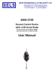
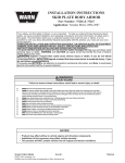
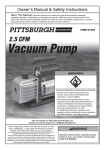
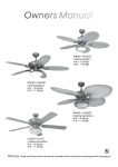
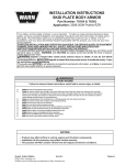
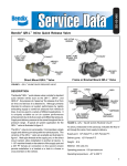
SD-08-203
®
Bendix® DRO Unloader Valve
4
CONTROL
ATTACHES
TO THE
EXHAUST OF
THE DRO VALVE
1
SUPPLY
21
DELIVERY
3
EXHAUST
FIGURE 1 - DRO UNLOADER VALVE
FIGURE 2 - SILENCER
DESCRIPTION
exhaust to atmosphere. Any air pressure created by the
compressor during the unload operations flows out the
DRO unloader valve to atmosphere.
The Bendix® DRO unloader valve allows an air dryer
with a turbo-cutoff valve to be used as a discharge line
unloaded dryer. The DRO valve allows discharge air
from the compressor to be exhausted to the atmosphere
in the unloaded mode of operation. Some compressors
are designed for discharge line unloading instead of head
unloading. When the DRO valve is placed in the discharge
line it allows both the compressor and the dryer, with turbocutoff, to function properly. The DRO valve can be used to
convert a head unloaded compressor to a discharge line
unloaded compressor.
The exhaust (3) can be directed away from the valve using
a 3/4” rubber hose. The hose should be securely fastened
to the frame and should not run uphill or contain any kinks
or sharp bends.
An optional silencer, as shown in Figure 2, is available
to reduce noise level during the unloaded operation. The
silencer snaps into the bottom of the exhaust port (3).
REMOVAL
OPERATION (SEE FIGURE 1)
1. Disconnect the supply and delivery line fittings.
The DRO unloader valve discharges air in the compressor
discharge line to the atmosphere. During the charging
operation of the compressor, air travels into the supply port
(1) of the DRO valve. When the air brake system reaches
the cut-out pressure, a pneumatic signal from the governor
is sent to the control port (4) of DRO unloader valve. The
pneumatic signal opens the DRO valve exhaust port (3)
allowing air pressure in the compressor discharge line to
2. Remove the mounting hardware that secures the
DRO unloader valve to the frame rail or mounting
surface.
1
INSTALLATION
The DRO valve can be installed in two configurations,
series or parallel.
Series Configuration
The series configuration, shown in Figure 3, allows all the
compressor discharge air to pass through the valve and
into the dryer or reservoir.
TO THE
CONTROL
PORT OF THE
AIR DRYER
GOVERNOR
FROM THE
RESERVOIR
COMPRESSOR
TO THE SUPPLY
PORT OF THE
AIR DRYER
DRO
UNLOADER
VALVE
Parallel Configuration
The parallel configuration, shown in Figure 4, allows the
DRO unloader valve to be mounted using a branch circuit.
This branch circuit provides the flexibility of installing the
unloader valve in a more convenient location. The branch
line should not run uphill or have kinks or sharp bends that
may trap condensed liquids.
DRO
UNLOADER
VALVE
TO THE SUPPLY
PORT OF THE AIR
DRYER
TO THE
CONTROL
PORT OF THE
AIR DRYER
PORT 21 MUST
BE PLUGGED
FROM THE
RESERVOIR
FIGURE 4 - PARALLEL CONFIGURATION
1. Locate a position in the discharge line of the
compressor where the DRO valve can be mounted.
The valve must be mounted at the same height or
below the compressor outlet.
2. Secure the DRO valve using 5/16” grade 5 or higher
bolts. It is not recommended to install the valve directly
on to the engine or compressor.
2
4. For a series configuration, the delivery line out of the
DRO should be connected to the air brake dryer or
reservoir tank.
5. For a parallel configuration, the delivery port out of the
DRO must be plugged.
6. The supply and delivery ports are 22 mm metric
threads. The control port is 12 mm metric threads.
Consult a fitting supplier for conversion fittings.
7. Make sure there is a line from the governor unloader
port to the DRO valve control port.
8. Test all connections for leaks.
FIGURE 3 - SERIES CONFIGURATION
GOVERNOR
3. For series installation, install a discharge line from the
compressor to the DRO valve, as shown in Figure 3.
For parallel installation add another discharge line
into the existing compressor discharge line using a
tee fitting. Connect the opposite end of this new line
to the DRO unloader valve as shown in Figure 4. The
valve must be at the same height or lower than the
discharge line.
9. Start the engine and allow the system to reach cutout pressure. The valve should open allowing air to
exit the exhaust port. A silencer, shown in Figure 2, is
recommended to reduce the noise level out of the DRO
valve when exhausting. Bendix provides a silencer that
snaps onto the exhaust port the DRO.
10.Fan the brakes until system cut-in is reached. The
DRO valve exhaust should shut allowing the air brake
system pressure to increase until cut-out pressure is
reached.
Note: The operating range of the DRO unloader valve is
from -40°F to 300°F. The DRO valve must be installed with
sufficient discharge line length to prevent the air dryer inlet
temperature from exceeding 160°F.
To prevent failure or freeze-ups, the control air into the
DRO valve must be free of liquid water and fluids and the
maximum inlet pressure to the DRO valve is 174 PSI.
GENERAL SAFETY GUIDELINES
WARNING! PLEASE READ AND FOLLOW
THESE INSTRUCTIONS TO AVOID PERSONAL
INJURY OR DEATH:
When working on or around a vehicle, the
following general precautions should be
observed at all times.
1.
2.
3.
4.
Park the vehicle on a level surface, apply the
parking brakes, and always block the wheels.
Always wear safety glasses.
Stop the engine and remove ignition key when
working under or around the vehicle. When
working in the engine compartment, the engine
should be shut off and the ignition key should
be removed. Where circumstances require
that the engine be in operation, EXTREME
CAUTION should be used to prevent personal
injur y resulting from contact with moving,
rotating, leaking, heated or electrically charged
components.
Do not attempt to install, remove, disassemble
or assemble a component until you have read
and thoroughly understand the recommended
procedures. Use only the proper tools and
observe all precautions pertaining to use of those
tools.
If the work is being performed on the vehicle’s
air brake system, or any auxiliary pressurized air
systems, make certain to drain the air pressure
from all reservoirs before beginning ANY work
on the vehicle. If the vehicle is equipped with
an AD-IS ® air dryer system or a dryer reservoir
module, be sure to drain the purge reservoir.
5.
Fo ll ow in g t h e ve hi c l e m a nu f a c t u r e r ’s
recommended procedures, deactivate the
electrical system in a manner that safely removes
all electrical power from the vehicle.
6.
Never exceed manufacturer’s recommended
pressures.
7.
Never connect or disconnect a hose or line
containing pressure; it may whip. Never remove
a component or plug unless you are certain all
system pressure has been depleted.
8.
Use only genuine Bendix ® replacement parts,
components and kits. Replacement hardware,
tubing, hose, fittings, etc. must be of equivalent
size, type and strength as original equipment and
be designed specifically for such applications and
systems.
9.
Components with stripped threads or damaged
parts should be replaced rather than repaired.
Do not attempt repairs requiring machining or
welding unless specifically stated and approved
by the vehicle and component manufacturer.
10. Prior to returning the vehicle to service, make
certain all components and systems are restored
to their proper operating condition.
11. For vehicles with Automatic Traction Control
(ATC), the ATC function must be disabled (ATC
indicator lamp should be ON) prior to performing
any vehicle maintenance where one or more
wheels on a drive axle are lifted off the ground
and moving.
3
4
BW2789 © 2009 Bendix Commercial Vehicle Systems LLC All rights reserved. 12/2009 Printed in U.S.A.