1
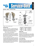
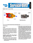
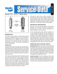
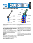
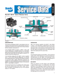
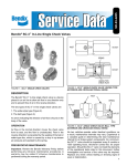
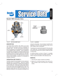
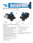
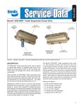
SD-03-906
®
Bendix® QR-L™ Inline Quick Release Valve
WRENCH
FLAT
SUPPLY PORT
(MALE PIPE
THREAD)
NUT & STAR
WASHER
EXHAUST
WRENCH
FLAT
SUPPLY PORT
(FEMALE PIPE
THREAD)
EXHAUST
DELIVERY
PORT
DELIVERY
PORT
Direct Mount QR-L™ Valve
Frame or Bracket Mount QR-L™ Valve
FIGURE 1 - QR-L™ INLINE QUICK RELEASE VALVE
DESCRIPTION
The Bendix® QR-L™ quick release valve is similar to standard
quick release valves such as the QR-1™, QR-N™, and
QRN-2™. Its purpose is to “speed up” the release of air from
air lines and devices it is attached to. Although primarily
intended to enhance air system performance by rapidly
exhausting supply or control air pressure from vehicle air
lines, it can be used in a variety of different applications. It
is uniquely suitable as an air system performance
enhancement due to its 0 psi crack and differential pressure.
Supply and delivery pressure is the same throughout the air
pressure range. A typical air system application for the
QR-L™ valve is illustrated in figure 3.
The QR-L™ valve is non-serviceable. It incorporates a single
supply and delivery port along with two exhaust ports. Two
versions of the QR-L™ valve are available as illustrated in
figure 1. Male pipe threads at the supply port, on the direct
mount version, allow installation in another air device. A
1-1/8” machine thread on the exterior of the supply port and
a 3/8” PT female air connection on the second version
permits installation in a bracket or a hole in a frame or
cross member on the vehicle.
BODY
CRIMPED TO
CAP
O-RING
BODY
DELIVERY
PORT
SUPPLY
PORT
CAP
3 AIR CHANNELS
(0 PSI CRACK &
DIFFERENTIAL)
DIAPHRAGM
EXHAUST
DIAPHRAGM
FIGURE 2 - QR-L™ INLINE QUICK RELEASE VALVE
An arrow, embossed in the cast body, indicates the flow of
air through the valve, from supply to delivery.
Supply port: 1/2"-Male P.T. or 3/8"-Female P.T.
Delivery ports: 1/2" Female P.T.
Weight: .6 lb.
Material: Die cast zinc
Operating pressure: 150 psi maximum
Operating temperature: -40° to 200° F
1
Exhaust
Tractor
Protection
Valve
Service
Brake
Valve
Supply
Control
Line QR-L™
Valve
Trailer
Control
Valve
Delivery
Diaphragm
Exhaust
Trailer
Supply Valve
Supply Line
QR-L™
Valve
FIGURE 5 QR-L™ INLINE QUICK RELEASE VALVE BALANCED
MODE
Exhaust
FIGURE 3 TYPICAL QR-L™ INLINE QUICK RELEASE VALVE
AIR SYSTEM APPLICATION
Supply
OPERATION
0 psi Crack & Differential Pressure
Unlike standard quick release valves, the QR-L™ valve
maintains the same pressure at the supply and delivery
ports (0 psi crack and differential) throughout the entire
pressure range during both apply and release modes. Three
radial channels in the cap, along with a specially shaped
diaphragm, provide the QR-L™ valve with this feature.
Delivery
Diaphragm
Exhaust
FIGURE 6 QR-L™ INLINE QUICK RELEASE VALVE RELEASE
MODE
Apply
When air pressure enters the supply port, it causes the
center portion of the diaphragm to seal the exhaust in the
body. Supply air pressure simultaneously forces the edges
of the diaphragm away from its seat on the cap, allowing air
to flow freely out the delivery port. Delivery pressure is the
same as supply pressure.
Balance
When delivery air pressure (pressure beneath diaphragm)
is equal to supply air pressure above the diaphragm, the
outer edges of the diaphragm seat against the cap. The
exhaust remains sealed because air pressure bears against
the center portion of the diaphragm from one side only.
Exhaust
Release
When air pressure is removed or reduced rapidly at the
QR-L™ valve supply port, the air pressure on the delivery
side of the diaphragm holds the outer edge of the diaphragm
against its seat on the cap while simultaneously moving
the center portion away from the exhaust port in the body.
Air from the delivery port flows out the exhaust ports. If air
pressure is reduced slowly at supply port, air may not flow
out the exhaust ports.
When delivery air pressure is fully exhausted, the diaphragm
will return to its natural state, with its outer edges seated
on the cap and the center portion seated against the exhaust
in the body.
WARNING! PLEASE READ AND FOLLOW
THESE INSTRUCTIONS TO AVOID
PERSONAL INJURY OR DEATH:
Supply
When working on or around a vehicle, the following
general precautions should be observed at all times.
Delivery
Diaphragm
Exhaust
™
FIGURE 4 QR-L INLINE QUICK RELEASE VALVE AIR APPLIED
TO SUPPLY PORT
2
1. Park the vehicle on a level surface, apply the
parking brakes, and always block the wheels.
Always wear safety glasses.
2. Stop the engine and remove ignition key when
working under or around the vehicle. When
working in the engine compartment, the engine
should be shut off and the ignition key should be
removed. Where circumstances require that the
engine be in operation, EXTREME CAUTION should
be used to prevent personal injury resulting from
contact with moving, rotating, leaking, heated or
electrically charged components.
3. Do not attempt to install, remove, disassemble or
assemble a component until you have read and
thoroughly understand the recommended
procedures. Use only the proper tools and observe
all precautions pertaining to use of those tools.
4. If the work is being performed on the vehicle’s air
brake system, or any auxiliary pressurized air
systems, make certain to drain the air pressure from
all reservoirs before beginning ANY work on the
vehicle. If the vehicle is equipped with an AD-IS™
air dryer system or a dryer reservoir module, be
sure to drain the purge reservoir.
5. Following
the
vehicle
manufacturer’s
recommended procedures, deactivate the electrical
system in a manner that safely removes all
electrical power from the vehicle.
6. Never exceed manufacturer’s recommended
pressures.
7. Never connect or disconnect a hose or line
containing pressure; it may whip. Never remove a
component or plug unless you are certain all
system pressure has been depleted.
8. Use only genuine Bendix ® replacement parts,
components and kits. Replacement hardware,
tubing, hose, fittings, etc. must be of equivalent
size, type and strength as original equipment and
be designed specifically for such applications and
systems.
9. Components with stripped threads or damaged
parts should be replaced rather than repaired. Do
not attempt repairs requiring machining or welding
unless specifically stated and approved by the
vehicle and component manufacturer.
10. Prior to returning the vehicle to service, make
certain all components and systems are restored
to their proper operating condition.
SERVICE CHECKS
PREVENTIVE MAINTENANCE
3. Test all air fittings for excessive leakage and tighten as
needed. Perform OPERATIONAL AND LEAKAGE
TESTS before placing the vehicle back into service.
Important: Review the Bendix Warranty Policy before
performing any intrusive maintenance procedures. A warranty
may be voided if intrusive maintenance is performed during
the warranty period.
No two vehicles operate under identical conditions, as a
result, maintenance intervals may vary. Experience is a
valuable guide in determining the best maintenance interval
for air brake system components. At a minimum, the QR-L™
valve should be inspected every 12 months or 3600 operating
hours, whichever comes first, for proper operation. Should
the QR-L™ valve not meet the elements of the operational
tests noted in this document, further investigation and service
of the valve may be required.
1. Remove any accumulated contaminants. Visually
inspect the valve’s exterior for physical damage. Replace
the valve if excessive physical damage is noted.
2. Inspect all air lines connected to the valve for signs of
wear or physical damage. Repair or replace as
necessary.
OPERATIONAL AND LEAKAGE TESTS
1. Block the vehicle’s wheels and fully charge the air
system.
2. Apply and release air pressure rapidly to the QR-L™ valve
several times and check for prompt response.
3. With air pressure applied to the supply port, apply a
soap solution to the QR-L™ valve exhaust ports. Leakage
of a 1” bubble in 5 seconds is permissible.
4. With the brakes still applied to the supply port, apply a
soap solution around the valve where the cap and body
are joined. No leakage at this point is permitted.
If the valve does not function as described, or if leakage is
excessive, replace it at any authorized parts outlet.
REMOVAL
1. Identify and mark or label all air lines and their
connections to the QR-L™ valve. Then disconnect the
air lines. Use the QR-L™ valve wrench flat, closest to
the air line or fitting being removed.
2. Remove the QR-L™ valve from the vehicle. Retain the
mounting hardware, if any.
INSTALLATION
1. Install the QR-L™ valve on the vehicle using the mounting
hardware, if any, saved during removal.
2. Reconnect all air lines to the valve using the identification
made during removal. Note: An arrow embossed in the
body of the vale indicates the direction of air flow and
points toward the delivery port. Use the QR-L™ valve
wrench flat, closest to the air line or fitting being installed.
NOTE: The construction of the QR-L™ valve prevents
disassembly/assembly. It is a non-serviceable device
and cannot be repaired. If the QR-L™ valve does not
meet the operational and leakage tests, it must be
replaced. Replacements are available at any
authorized Bendix parts outlet.
3
4
BW1808 © 2004 Bendix Commercial Vehicle Systems LLC All rights reserved. 3/2004 Printed in U.S.A.