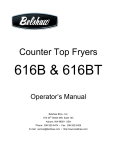
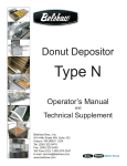
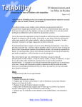
1
Electric Fryer Models 618L, 624, and 634 Operator’s Manual 618L & 624: 634 : To unpack the fryer and transport it to the workstation: If you accept the machine from the shipping company, you are, in effect, saying that the machine is in good condition, and you must pay for the machine. Belshaw cannot pay for shipping damage, because the freight company has accepted the machine from Belshaw in good condition, and is responsible for its safe delivery. For your protection, inspect the machine to see that no parts are bent, scratched, or otherwise damaged. If any damage has occurred in shipping, file a freight claim with the shipping company immediately. 1. Use a fork lift to transport the shipping crate to the work station. 2. Break down the shipping crate. 3. Remove all the packing materials from the fryer. These include foam, tape, brown paper, plastic, and white protective coating. 4. Position the fryer to allow sufficient space on either end of the machine for any equipment you plan to use with it. IMPORTANT Keep this manual for future reference. EQUIPMENT RECORD Please provide the information below when you correspond with us about your machine. Purchased by _____________________________________________________________________ Installed by ______________________________________________________________________ Date of Installation ________________________________________________________________ Model number ___________________________________________________________________ Serial number 0303 MN-1126EN Belshaw Bros., Inc. 1750 22nd Avenue South Seattle, WA 98144-4590 USA Phone: (206) 322-5474 • Fax: (206) 322-5425 Toll Free: (800) 578-2547 Email: [email protected] • http://www.belshaw.com Contents Sections 1 Installation 1 Unpacking the Fryer Initial Cleaning Installing the Fryer Moving the Fryer Mounting the Drain Tray 1 1 1 2 2 2 Operation 4 3 Cleaning 6 Cleaning the Exterior Surfaces Cleaning the Frying Screen Cleaning the Kettle Removing the Shortening Washing Rinsing Drying 6 6 6 6 7 8 8 4 9 Troubleshooting Appendixes A Donut-Making Helps 13 Tips on Making Quality Cake Donuts Calculating Correct Water Temperature Ratios of Plunger Sizes to Donut Weights Temperature Conversion 13 14 14 14 B Electrical Components 15 Testing the Continuity of the Toggle Switch Testing the Continuity of the Thermostat 15 16 Belshaw Bros., Inc. 1750 22nd Ave. S. Seattle, WA 98144 Phone 206-322-5474 Fax 206-3225425 618L, 624, and 634 Electric Fryers MN-1126EN iii C Parts Lists 17 618L Fryer 624 Fryer 634 Fryer D Wiring Diagrams 618L Fryer 624 Fryer 634 Fryer E 18 24 31 (618L-4018) (624-4024) (634-4050) 37 Insert Insert Insert Limited Warranty Insert Figures B-1. B-2. Toggle Switch Continuity Test Thermostat Terminals 20 21 Belshaw Bros., Inc. 1750 22nd Ave. S. Seattle, WA 98144 Phone 206-322-5474 Fax 206-3225425 iv MN-1126EN 618L, 624, and 634 Electric Fryers Preface The 618L, 624, and 634 Electric Fryers are designed to fry cake and yeast-raised donut products. Each must be bolted to a flat, dry floor. The operator should stand opposite the heater head. Hot shortening can cause serious burns. Make sure that the system and the shortening are cool before attempting any cleaning, adjustment, disassembly, or repair. The operator must work safely at all times and read this manual and follow its instructions and warnings. A thorough understanding of how to install, maintain, and safely operate the fryer will prevent production delays and injuries. To avoid electrocution or other injury, unplug the machine before attempting any cleaning, adjustment, disassembly, or repair. Be careful never to get shortening, water, or other materials on the floor. If anything does get spilled on the floor, mop it up immediately. Materials on the floor can cause people to slip or fall, resulting in serious injury or loss of life. To prevent unintentional startup and possible fire, unplug the machine if there is a local power outage. When the power is restored, it is safe to plug the machine in again. To avoid electrocution, make sure that all electrical cords are not frayed or cracked and that they do not pass through any water or shortening. Make sure that all electrical cords are routed so that no one will trip over them. Heed the following warnings and all other warnings that appear in this manual: Make sure the machine is bolted securely to the floor. Doing so will prevent the machine from moving, tipping, or falling, which could cause serious injury. To avoid damaging the machine, never use force to assemble, disassemble, operate, clean, or maintain it. Never let water and hot shortening come in contact with each other. Moisture causes hot shortening to spatter, which may cause serious burns. Do not overfill the kettle with shortening. If shortening overflows the kettle, it could cause serious burns or could cause someone to slip on the floor and be seriously injured. Belshaw Bros., Inc. 1750 22nd Ave. S. Seattle, WA 98144 Phone 206-322-5474 Fax 206-3225425 618L, 624, and 634 Electric Fryers MN-1126EN v 1 Installation Unpacking the Fryer Installing the Fryer 1. Use a fork lift to transport the shipping crate to the work station. 1. 2. Break down the shipping crate. Make sure the power requirements of the machine, found on the data plate on the back of the heater head assembly, match your power source. 3. Remove all the packing materials from the fryer. These include foam, tape, brown paper, plastic, and white protective coating. 2. Using a fork lift or pallet jack, lift the fryer cabinet and screw each leg in as far as it will go. 4. Position the fryer to allow sufficient space on either end of the machine for any equipment you plan to use with it. 3. Set the fryer cabinet on a flat, dry floor. 4. Level the fryer. Follow these steps: a. Check to see if the fryer is level. To do so, place a level across the top of the fryer cabinet. Initial Cleaning Clean your fryer before using it. Wipe the inside of the kettle with a soft, damp cloth. Dry the kettle thoroughly. b. If the fryer is not level, lift the fryer using a fork lift or pallet jack, and turn the legs to adjust them. c. Using the fork lift or pallet jack, lower the fryer to the floor. Be sure that all the legs rest on the floor when the fryer is level. WARNING To avoid electrocuting yourself or damaging the machine, never allow water, steam, cleaning solution, or other liquid to enter the heater head or the electrical box. 5. Bolt the fryer to the floor. The foot of each leg has two holes in it for this purpose. WARNING WARNING Never let water and hot shortening come in contact with each other. Moisture causes hot shortening to spatter, which may cause serious injury. Prior to use, make sure the kettle and any other parts you have washed are dry. To avoid serious burns, other injury, or death, make sure the fryer is securely fastened to the floor so it will not tip or fall over. 9. Connect the fryer to a properly grounded power source. Belshaw Bros., Inc. 1750 22nd Ave. S. Seattle, WA 98144 Phone 206-322-5474 Fax 206-3225425 618L, 624, and 634 Electric Fryers MN-1126EN 1 Moving the Fryer Mounting the Drain Tray If you ever want to move the fryer to a different workstation, follow this procedure: If you ever want to mount the drain tray on the opposite side of the fryer, follow the steps below. You cannot move the drain tray if your fryer has a Belshaw Shortening Melter (FM) mounted on it. 1. Turn off the fryer and disconnect it from the power source. 2. Allow the machine and the shortening to cool. 3. 1. Remove the two acorn nuts on the ends of the drain tray hinge shaft. WARNING 2. Slide the drain tray hinge shaft out of the drain tray mount brackets. Do not touch hot shortening. It can cause serious burns. 3. Lift off the drain tray. 4. Remove the bolts and washers that hold the drain tray mount brackets in place. Remove the mount brackets. 5. Tilt the heater head back and lock it in place. 6. Loosen the set screws in the drain valve extension knob on the side of the cabinet. Remove the knob. 7. Inside the cabinet, there is a set collar on the drain valve extension rod. Loosen the set screw in the set collar. Slide the set collar toward the drain valve. Remove the extension rod and the bushing. 8. Remove the hole plug from the hole in the opposite side of the cabinet and insert the bushing in its place. Install the hole plug in the hole where the bushing was. 9. Remove the kettle from the cabinet, turn it 180º, and put it back in the cabinet. Remove the shortening from the fryer as explained in “Removing the Shortening” in Section 3. WARNING To avoid burns, falls, other injury, or death, never attempt to move the fryer when it has shortening or other liquid in it. WARNING Thoroughly clean and dry the floor if shortening is spilled. Materials on the floor can cause people to slip or fall, resulting in serious injury or loss of life. 4. Remove the bolts that secure the fryer to the floor. 5. Using a fork lift, transport the machine to the new workstation. 6. Level the fryer, bolt it to the floor, and connect it to the power source, as explained in “Installing the Fryer” above. 10. Install the extension rod and the drain valve extension knob at the new location. To do this, reverse the procedure outlined in steps 6 and 7. 11. Remove the two drain tray support rests that are mounted on the outside of the cabinet. Each support rest is held in place by two hex-head machine screws, two hex nuts, two internal tooth lock washers, and two flat washers. 12. Install the drain tray support rests on the opposite side of the cabinet. Belshaw Bros., Inc. 1750 22nd Ave. S. Seattle, WA 98144 Phone 206-322-5474 Fax 206-3225425 2 MN-1126EN 618L, 624, and 634 Electric Fryers 13. Install the drain tray mount brackets (removed in step 4) on the opposite side of the fryer. 14. Put the drain tray in place, so its holes line up with the holes in the mount brackets. 15. Slide the drain tray hinge shaft through the holes in the mount brackets and the drain tray. 16. Tighten the acorn nuts (removed in step 1) on the ends of the drain tray hinge shaft. Belshaw Bros., Inc. 1750 22nd Ave. S. Seattle, WA 98144 Phone 206-322-5474 Fax 206-3225425 618L, 624, and 634 Electric Fryers MN-1126EN 3 Operation Read each step completely before doing what it tells you to do. 1. If you are frying yeast-raised donuts, install the proofer or feed table. Refer to the proofer or feed table manual for complete installation and operation instructions. 2. Make sure the drain valve is closed. 3. Put enough shortening in the kettle to completely cover the heating elements, thermocouple, and high-temperature limit control probe. 2 4. The “Power On” pilot light on top of the heater head will light up. 5. Set the thermostat to 250 F/121 C. The “Heating” pilot light on top of the heater head will light up, indicating that the shortening has not yet reached the selected temperature. 6. Continue adding shortening to the kettle until it reaches the proper depth for frying. Use one of the following methods. For safety reasons, we recommend the first method, and discourage you from using any other method. Put shortening in the kettle using one of these methods: Move the on/off switch to the ON position. The switch is located inside the fryer cabinet, on the right hand side. If you have a Belshaw Shortening Melter (FM) attached to the fryer, use the FM to melt shortening and transfer it to the kettle. See the FM manual. WARNING Use a Belshaw Shortening Melter (FM) to melt shortening and transfer it to the kettle. See the FM manual. Melt shortening in a pan on the stove and pour it into the kettle. Very carefully put solid shortening into the kettle. Hot shortening causes severe burns. Melt shortening in a pan on the stove and pour it into the kettle. Put solid shortening into the kettle, packing it tightly around the heating elements, thermocouple, and hightemperature limit control probe. WARNING To avoid serious burns, be very careful not to splatter hot shortening when you add shortening to the kettle. WARNING Because shortening expands as it increases in temperature, put shortening in the kettle gradually. Let the shortening in the kettle heat up before you add more. Air spaces can cause the shortening to overheat and catch on fire. 7. After all of the shortening has melted, set the thermostat to the desired frying temperature. Belshaw Bros., Inc. 1750 22nd Ave. S. Seattle, WA 98144 Phone 206-322-5474 Fax 206-3225425 4 MN-1126EN 618L, 624, and 634 Electric Fryers The “Heating” pilot light will go out if the high temperature limit control breaks the circuit. Note: If the high temperature limit control does break the circuit, push the red reset button on the back of the heater head. 8. Wait for the shortening to reach the desired temperature. 9. If you are frying cake or French donuts, move the cutter into place over the fryer. Refer to the cutter manual for complete installation and operation instructions. If you are frying yeast-raised donuts using a feed table, load proofing cloths on the feed table. Refer to the feed table manual for complete installation and operation instructions. WARNING To avoid serious burns, when the fryer is operating, do not touch the flue, exhaust manifold, stacks, gas burners, or any part of the fryer that is in contact with hot shortening. Keep clear from the area above the flue outlet. CAUTION To avoid damaging the machine, do not operate the conveyor until all the shortening has melted. 10. Continue supplying shortening to the kettle as required. Keep the kettle filled up to the “Oil Level” marks on the side. 11. When you are done frying donuts, move the on/off switch to the OFF position. Belshaw Bros., Inc. 1750 22nd Ave. S. Seattle, WA 98144 Phone 206-322-5474 Fax 206-3225425 618L, 624, and 634 Electric Fryers MN-1126EN 5 Cleaning For your safety, observe the following warnings throughout the entire cleaning process. 3 Cleaning the Frying Screen 1. In a sink or a dishwasher, wash the frying screen using warm water and mild detergent. Do not use an abrasive cleaner or scraper. 2. Rinse the frying screen in clear water. 3. Dry the frying screen thoroughly, using a soft cloth, before you use it again. WARNING Thoroughly clean and dry the floor if shortening, water, or other materials are spilled. Materials spilled on the floor can cause serious injury or loss of life. WARNING WARNING To avoid electrocuting yourself or damaging the machine, never allow water, steam, shortening, cleaning solution, or any other liquid to enter the electrical box or the heater head. WARNING To avoid being burned in an explosion, never use any flammable materials for cleaning. Cleaning the Exterior Surfaces 1. 2. Clean the polished and painted surfaces of the fryer with a soft, damp cloth. Use a nonabrasive cleaner to remove any discoloration. Polish these surfaces with a soft, dry cloth. Dry the frying screen thoroughly. Moisture causes hot shortening to spatter, which may cause serious injury. 4. Check the frying screen to make sure no metal is flaking off of it. If the screen is flaking, replace it immediately, so you do not get metal particles in your product. Cleaning the Kettle There are four basic steps to cleaning the kettle: removing the shortening, washing, rinsing, and drying. You must perform all four steps and perform them in the order listed. Removing the Shortening WARNING To avoid being burned or electrocuted, disconnect the fryer from the power source before cleaning it. 1. Disconnect the machine from the power source. 2. Let the shortening cool to 100 F/38 C. Belshaw Bros., Inc. 1750 22nd Ave. S. Seattle, WA 98144 Phone 206-322-5474 Fax 206-3225425 6 MN-1126EN 618L, 624, and 634 Electric Fryers 3. Place a Belshaw Shortening Filter or a large metal container under the drain valve of the fryer. 8. Tilt the heater head assembly out of the fryer and lock it in place. 9. Using a non-abrasive, non-metallic spatula, scrape the sediment and any remaining shortening through the drain valve. WARNING Do not use a plastic container. If the shortening is not cool enough, the container will melt, possibly causing you to be burned, and causing shortening to get on the floor. 4. 5. Open the drain valve by turning the drain valve extension knob on the side of the fryer cabinet. Allow all the shortening to drain into the Shortening Filter or metal container. If you are using a metal container, watch it to make sure the shortening does not overflow. If the container becomes full, close the drain valve, put another metal container under the drain valve, and open the drain valve again. WARNING Do not allow the shortening to overflow the containers. Shortening will get on the floor, and if the shortening is not cool enough, you may be burned. WARNING Thoroughly clean and dry the floor if shortening is spilled. Shortening on the floor can cause serious injury or loss of life. 6. If you have drained the shortening into a metal container and you wish to re-use the shortening, set the container of shortening aside. Place another suitable container under the drain valve. 7. Brush accumulated carbon from the heating elements. Accumulated carbon causes corrosion and poor heat recovery. 10. Close the drain valve. 11. If your fryer has a Belshaw Shortening Melter (FM) connected to it, install the plug into the reservoir nipple. Washing 1. Carefully pour hot water into the kettle, up to the normal level of the shortening. Add trisodium phosphate or another appropriate cleaner. 2. Scrub the inside of the kettle. Do not use any abrasive cleaners or scrapers. WARNING To avoid being burned, be very careful as you work with hot cleaning solution. Never put your hands in the solution. Wear gloves and long sleeves in case any solution splashes. 3. Allow the cleaning solution to cool to the touch. 4. Place a large metal container under the drain valve. WARNING Do not use a plastic container. If the cleaning solution is not cool enough, the container will melt; possibly causing you to be burned, and causing cleaning solution to get on the floor. 5. Open the drain valve and allow the cleaning solution to drain into the container. Belshaw Bros., Inc. 1750 22nd Ave. S. Seattle, WA 98144 Phone 206-322-5474 Fax 206-3225425 618L, 624, and 634 Electric Fryers MN-1126EN 7 6. Watch the container to make sure the cleaning solution does not overflow. If the container becomes full, close the drain valve, put another large metal container under the drain valve, and open the drain valve again. 4. Open the drain valve and allow the water to drain into the container. 5. Watch the container to make sure the water does not overflow the container. If the container becomes full, close the drain valve, put another large metal container under the drain valve, and open the drain valve again. WARNING Do not allow the cleaning solution to overflow the container. Cleaning solution will get on the floor, and if the solution is not cool enough, you may be burned. 7. When the draining is complete, close the drain valve. 8. Carefully carry the container(s) to the sink and slowly pour the solution into the sink. WARNING Thoroughly clean and dry the floor if cleaning solution is spilled. Liquid on the floor can cause serious injury or loss of life. Rinsing 1. Carefully pour clean, hot water into the kettle, up to the normal level of the shortening. If the cleaner you have used requires that you add a neutralizer, do so now. 2. Allow the water to sit for 5-10 minutes. Then allow it to cool to the touch. 3. Place a large metal container under the drain valve. WARNING Do not allow the water to overflow the container. Water will get on the floor, and if the water is not cool enough, you may be burned. 6. When the draining is complete, close the drain valve. 7. Carefully carry the container(s) to the sink and slowly pour the water into the sink. WARNING Thoroughly clean and dry the floor if water is spilled. Water on the floor can cause serious injury or loss of life. Drying Dry the inside of the kettle thoroughly, using a soft cloth. WARNING Dry the kettle thoroughly. Moisture causes hot shortening to spatter, which may cause serious injury. WARNING Do not use a plastic container. If the water is not cool enough, the container will melt, possibly causing you to be burned, and causing cleaning solution to get on the floor. Belshaw Bros., Inc. 1750 22nd Ave. S. Seattle, WA 98144 Phone 206-322-5474 Fax 206-3225425 8 MN-1126EN 618L, 624, and 634 Electric Fryers Troubleshooting 4 If you have a problem with your fryer that you cannot solve, call your dealer or another qualified technician. If your dealer cannot help you, please call Belshaw Bros. at (206)322-5474. When you call, please specify the following: The model name of the machine. The serial number of the machine. The voltage, phase, and cycle of the machine. CAUTION If you perform repairs yourself or have them performed by anyone other than a service technician authorized by Belshaw Bros., you do so at your own risk. WARNING Disconnect the machine from the power source before disassembling, repairing, or wiring. Belshaw Bros., Inc. 1750 22nd Ave. S. Seattle, WA 98144 Phone 206-322-5474 Fax 206-3225425 618L, 624, and 634 Electric Fryers MN-1126EN 9 THE FRYER WILL NOT TURN ON OR HEAT Possible Causes What To Do The on/off switch is not in the ON position. Move the on/off switch to the ON position. The on/off switch is located inside the fryer cabinet, on the right hand side. The thermostat is not turned on. Turn the thermostat knob to a setting that is high enough to make the “Heating” pilot light come on. The high-temperature limit control switch has been tripped. Press the red reset button on the back of the heater head. WARNING Before doing any of the following, turn off the machine and allow the shortening to cool. The primary power distribution circuit breaker has been tripped. Flip the circuit breaker. The circuit breaker is visible through an access cutout in the electrical box. (The electrical box is inside the cabinet, in the back.) A fuse is blown. Replace the fuse. THE HEATING ELEMENTS FAIL TO MAINTAIN THE PROPER TEMPERATURE Possible Causes What To Do WARNING Before doing any of the following, turn off the machine and allow the shortening to cool. The thermostat is out of adjustment. Re-calibrate the thermostat. See Appendix B, “Electrical Components.” The thermostat is defective. Replace the thermostat. Sediment has accumulated around the thermostat bulb. Remove the shortening from the fryer, as explained in Section 3, “Cleaning.” Remove the sediment from the thermostat bulb. Belshaw Bros., Inc. 1750 22nd Ave. S. Seattle, WA 98144 Phone 206-322-5474 Fax 206-3225425 10 MN-1126EN 618L, 624, and 634 Electric Fryers THE HEATING ELEMENTS WILL NOT HEAT Possible Causes What To Do The fryer’s circuit breaker has been tripped. Press the red reset button on the back of the heater head. The high-temperature limit control switch has been tripped. Press the red reset button on the back of the heater head. WARNING Before doing any of the following, turn off the machine and allow the shortening to cool. The contactor is defective. Replace the contactor. A heating element is defective. Replace the defective heating element. The high-temperature limit control is defective. Replace the high-temperature limit control. The thermostat is out of adjustment. Re-calibrate the thermostat. See Appendix B, “Electrical Components.” The thermostat is defective. Replace the thermostat. Belshaw Bros., Inc. 1750 22nd Ave. S. Seattle, WA 98144 Phone 206-322-5474 Fax 206-3225425 618L, 624, and 634 Electric Fryers MN-1126EN 11 Appendixes A Donut-Making Helps B Electrical Components C Parts Lists D Wiring Diagram E Limited Warranty Belshaw Bros., Inc. 1750 22nd Ave. S. Seattle, WA 98144 Phone 206-322-5474 Fax 206-3225425 12 MN-1126EN 618L, 624, and 634 Electric Fryers A Donut-Making Helps If the shortening is too cold, the donuts will spread too rapidly, will form large rings, will tend to crack open, will be too light in appearance, and will absorb too much shortening. Tips on Making Quality Cake Donuts Use the correct batter temperature. In general, the correct batter temperature is 75 -80 F/24 -27 C. Check the mix manufacturer’s instructions, as the recommended temperature range may vary. If the shortening is too deep, the donuts may not turn over when they reach the turner, causing them to cook unevenly. If the batter is too warm, the donuts will lack volume and may “ring out” or be misshapen. If the batter is too cold, the donuts will stay under the shortening too long, fry too slowly, and crack open or ball up. They may also absorb excess shortening and lose volume. Use the correct floor time. A floor time of 10 minutes between mixing and cutting allows the baking powder to react with the water. This helps the donuts attain the proper volume the proper level of shortening penetration. If the floor time exceeds 30 minutes, the mix will gas off, the donuts will lose volume and shape and will absorb too much shortening. Use the correct frying temperature. The correct shortening temperature for frying is 370 -380 F/188 -193 C. If the shortening is too hot, the donuts will fry too quickly on the outside and will lose volume. The donuts may also become dense inside. Maintain the proper shortening level. We recommend a distance of 1 1/4” between the cutter and the shortening. If the shortening is too shallow (too far below the cutter), the donuts may not drop flat, may turn over while submerging and surfacing, and may become irregular, cracked, or rough-crusted. Ensure that the donuts absorb the right amount of shortening. Donuts should absorb 1-1/2 to 3 oz/42 to 85 g of shortening per dozen, depending on their weight. You can achieve proper absorption by following tips 1-3. If the donuts do not absorb enough shortening, they will not keep well. If they absorb too much shortening, they will lose volume and may become misshapen. If this happens, follow tips 1-3, mix the batter a little longer than usual, turn the donuts as soon as they become golden brown, and turn the donuts only once. Belshaw Bros., Inc. 1750 22nd Ave. S. Seattle, WA 98144 Phone 206-322-5474 Fax 206-3225425 618L, 624, and 634 Electric Fryers MN-1126EN 13 Calculating Correct Water Temperature The following is an example of how to calculate the correct water temperature to use. You must use your own room temperature, dry mix temperature, desired batter temperature, and, if you are making yeast-raised donuts, estimated temperature increase during mixing. Cake Donuts Yeast-Raised Donuts F 72 +70 142 C 22.2 +21.1 43.3 F 72 +70 142 C 22.2 +21.1 43.3 Total B 75 x3 225 23.9 x3 71.7 80 x3 240 26.7 x3 80.1 Total B -Total A Desired water temp. for cake donuts 225 -142 83 F 71.7 -43.3 28.4 C 240 -142 98 80.1 -43.3 36.8 98 -30 68 F 36.8 -17 19.8 C Room temperature Dry mix temperature Total A Desired batter temperature Figure from above Temperature increase during mixing (average: 30 F/17 C) Desired water temperature for yeast-raised donuts Ratios of Plunger Sizes to Donut Weights The weights given are for donuts without icings or other toppings. They are provided for reference only, as weights vary according to the density of the batter. Plunger Size 1” 1 7/16” 1 9/16” 1 13/16” Donut Weight per Dozen 5-8 oz/142-227 g 10-17 oz/283-482 g 14-21 oz/397-595 g 19-23 oz/539-652 g Temperature Conversion To convert temperatures from Fahrenheit to Celsius, subtract 32 from F and divide the result by 1.8. For example, 212 F-32/1.8 = 100 C. To convert temperatures from Celsius to Fahrenheit, multiply C by 1.8 and add 32 to the result. For example, (100 C x 1.8) + 32 = 212 F. F C F C 55 60 65 70 75 80 325 330 12.8 15.6 18.3 21.2 23.9 26.7 162.8 165.6 340 345 350 355 360 365 370 375 171.1 173.9 176.7 179.4 182.2 185.0 187.8 190.6 Belshaw Bros., Inc. 1750 22nd Ave. S. Seattle, WA 98144 Phone 206-322-5474 Fax 206-3225425 14 MN-1126EN 618L, 624, and 634 Electric Fryers 335 168.3 380 193.3 Belshaw Bros., Inc. 1750 22nd Ave. S. Seattle, WA 98144 Phone 206-322-5474 Fax 206-3225425 618L, 624, and 634 Electric Fryers MN-1126EN 15 B Electrical Components This appendix explains how to test the continuity of electrical components in your fryer. These include the toggle switch and the thermostat. switch terminals The appendix also contains a document by the Robertshaw Controls Company, the maker of the thermostat we use in the 618L, 624, and 634. It explains how to check, adjust, and recalibrate the thermostat. Testing the Continuity of the Toggle Switch toggle switch + WARNING battery To avoid the possibility of electric shock, disconnect the machine from the power source before testing. _ 1. Disconnect the machine from the power source. 2. Disconnect the terminal wires from the switch. 3. Obtain a continuity tester or a volt-ohm meter. If neither of these instruments is available, make a continuity tester using a battery and a bulb. See Figure B-1. 4. Connect the wires of the continuity tester to the switch terminals, as shown in Figure B1, and test the switch in the ON and OFF positions. The switch should show continuity only when in the ON position. Figure B-1. Toggle Switch Continuity Test. Belshaw Bros., Inc. 1750 22nd Ave. S. Seattle, WA 98144 Phone 206-322-5474 Fax 206-3225425 16 MN-1126EN 618L, 624, and 634 Electric Fryers Testing the Continuity of the Thermostat WARNING To avoid the possibility of electric shock, disconnect the machine from the power source before testing. 1. Disconnect the machine from the power supply. 2. Disconnect the terminal wires from the thermostat. 3. Connect the continuity tester across the B terminals indicated in Figure B-2. This set of contacts should be closed whenever the thermostat is on. To test, start with the thermostat in the OFF position. Then turn the thermostat up until you hear a distinct click (at about the 175 F/79 C setting). At this time, there should be continuity across the B terminals. 4. Connect the continuity tester across the A terminals indicated in Figure B-2. Start with the thermostat in the OFF position and turn the thermostat up until you hear a distinct click. If there is no continuity (the indicator or light does not come on), proceed to step 5. 5. With the continuity tester still connected, turn the thermostat knob to OFF and remove the knob. There is an adjusting screw in the center of the knob stem. Turn it counterclockwise until there is continuity. If there is no continuity (the indicator or light does not come on), then the thermostat is defective. If there is continuity, proceed to step 6. setting of the thermostat until it does. Then recalibrate the thermostat according to the manufacturer’s instructions. If the indicator or light will not go off at any setting or recalibration, then the thermostat is defective. “B” terminals “A” terminals Figure B-2. Thermostat Terminals. 6. Immerse the thermostat sensing bulb in a pan of boiling water and set the thermostat at about 212 F/100 C. The continuity tester’s indicator or light should go off. If the indicator or light does not go off, increase the temperature Belshaw Bros., Inc. 1750 22nd Ave. S. Seattle, WA 98144 Phone 206-322-5474 Fax 206-3225425 618L, 624, and 634 Electric Fryers MN-1126EN 17 C Parts Lists The following pages contain lists of the parts that make up the 618L, 624, 634 Fryers. You can use the parts lists to order replacement parts. When you do, please provide electrical information about your fryer. Some of the part numbers vary according to the voltage, phase, and cycle of the machine. IMPORTANT The parts lists and assembly drawings are meant as guides. Because Belshaw constantly improves its products, parts lists and assembly drawings may not reflect the most recent design changes. Belshaw Bros., Inc. 1750 22nd Ave. S. Seattle, WA 98144 Phone 206-322-5474 Fax 206-3225425 18 MN-1126EN 618L, 624, and 634 Electric Fryers Belshaw Bros., Inc. 1750 22nd Ave. S. Seattle, WA 98144 Phone 206-322-5474 Fax 206-3225425 618L, 624, and 634 Electric Fryers MN-1126EN 19 FIGURE C-1. 618L FINAL ASSEMBLY. BILL OF MATERIAL ITEM QTY. PART NO. 1 1 or 618-1042 or BILL OF MATERIAL DESCRIPTION Pre-Wire Panel Assembly–U.L. ITEM QTY. PART NO. 28 1 624-40 DESCRIPTION Drain Nipple 1 or 618-1043 or Pre-Wire Panel Assembly–CSA and 208/236 Volt Export 29 1 618L-98 Drain Valve Extension Knob 1 or 618-1044 or Pre-Wire Panel Assy.–440/480 Volt, Transformer (Shown) (See Fig. B-2) 30 1 618L-516 Extension Rod Assembly 1 618-1048 Pre-Wire Panel Assembly–380 Volt Export 31 1 FT100-50 Set Collar 2 1 618-161 Electrical Box Cover 32 1 -------- 1” Plastic Insulating Bushing 3 1 or 618L-1044 or Cabinet Assembly–Painted 33 1 618-128 Label–Ground 1 618-1044SS Cabinet Assembly–Stainless Steel 34 1 618-131 Ground Lug 4 1 618-540 Electrical Box Assembly 35 1 -------- 1” EMT Locknut 5 1 618L-103 Label–”Drain Valve” 36 1 MDD-459 Label–”Warning” 6 1 EP18/24140 Label–”Belshaw” 37 1 618L-105 Label–”Warning,” Cutter Mounting 7 3 618-116 Label–”Caution–Hot” 38 4 624-143 Adjustable Leg 8 2 634-619 Bracket Plate Assembly 9 1 618-17 Door Knob FASTENERS 10 2 634-63 Cutter Column Mounting Bar Spacer 11 1 634-59 Heater Head Mounting Bracket–L.H. ITEM QTY. DESCRIPTION A 1 8 x 3/8 Slotted Round-Head Sheet Metal Screw 12 1 634-75 Bracket Sleeve B 8 1/4-20 x 5/8 Hex-Head Machine Screw 13 1 634-60 Heater Head Mounting Bracket–R.H. C 1 10-24 x 1-1/4 Socket-Head Cap Screw 14 1 618L-1515240 Heater Head Assembly–208/240 Volt (See Figure B-3) D 2 10-16 x 7/8 Hex Washer-Head Tek Screw 1 618L-1045 Heater Head Assembly–208/240 Volt, CSA and Export (See Figure B-3) E 2 10-16 x 5/8 Hex Washer-Head Tek Screw 1 618L-1023 Heater Head Assembly–380/440 Volt, Export (See Figure B-3) F 6 10-16 x 1/2 Hex Washer-Head Tek Screw 1 618L-1039 Heater Head Assembly–480 Volt, Domestic (See Figure B-3) G 8 10-24 x 3/8 Slotted Round-Head Machine Screw 15 1 -------- 1” Sealtite Conduit H 1 8-32 x 1-1/8 Slotted Truss-Head Machine Screw 16 1 -------- 1” x 90° Sealtite Connector J 1 8-32 x 1/4 Slotted Round-Head Machine Screw 17 1 618L-23 Drain Tray Hinge Shaft K 1 1/4-20 x 1/4 Socket-Head Flat-Point Set Screw 18 1 618-37 Drain Tray Support Rod L 1 1/4-28 x 1/4 Socket-Head Flat-Point Set Screw 19 1 618L1003SS Drain Tray Assembly M 6 5/16-18 Hex Nut 20 1 618L-7 Frying Screen N 7 1/4-20 Hex Nut 21 1 624-38 Drain Tray Support Rest–Rear P 9 10-24 Hex Nut 22 1 624-39 Drain Tray Support Rest–Front R 6 5/16 Flat Washer 23 1 -------- Snap Bushing (Heyco #2087) S 3 #10 Flat Washer 24 1 -------- 1-1/4” to 1” Reducing Washer T 4 1/4 Flat Washer 25 2 -------- Hole Plug (Heyco #2674) U 1 #8 Internal Tooth Lockwasher 26 1 618L1000SS Kettle Assembly V 11 1/4 Internal Tooth Lockwasher 27 1 624-11 Drain Valve W 8 #10 Internal Tooth Lockwasher Belshaw Bros., Inc. 1750 22nd Ave. S. Seattle, WA 98144 Phone 206-322-5474 Fax 206-322-5425 20 MN-1126EN 618L, 624, and 634 Fryers 618-1042 PRE-WIRE PANEL ASSEMBLY—U.L. BILL OF MATERIAL FASTENERS ITEM 1 QTY. 1 PART NO. 618-541 DESCRIPTION Pre-Wire Mounting Panel Assembly ITEM A QTY. 8 DESCRIPTION 10-16 x 1/2 Hex Washer-Head Tek Screw 2 2 624-136 Circuit Breaker–30 Amps B 4 #10 SAE Flat Washer 3 1 624-137 Circuit Breaker–15 Amps 4 1 624-138 Circuit Breaker Interior 5 2 624-144 Magnetic Contactor 6 1 (990-0165) Jumper (Marathon #SPA-409-2) 7 4 (995-0402) AWG #10 Red 105°C, 6” Long 618-1043 PRE-WIRE PANEL ASSEMBLY—CSA AND 208/236 VOLT EXPORT. BILL OF MATERIAL FASTENERS ITEM 1 QTY. 1 PART NO. 618-541 DESCRIPTION Pre-Wire Mounting Panel Assembly ITEM A QTY. 4 DESCRIPTION 10-16 x 1/2 Hex Washer-Head Tek Screw 2 1 618-129 Power Distribution Block B 2 10-16 x 5/8 Hex Washer-Head Tek Screw 3 2 624-144 Magnetic Contactor–40 Amps C 2 10-16 x 7/8 Hex Washer-Head Tek Screw D 2 #10 SAE Flat Washer 4 1 C200-30 Fuse Holder–Double Pole 5 2 C200-30A Fuse–FRN 5 Amp 6 1 618-133 Label–Control Circuit 7 4 (990-0152) Cable Tie, TY33M 8 2 (990-0504) R4149SF 18 Ga. #10 Red Hollingsworth Ring Terminal 9 2 (990-0502) R4142SF 18 Ga. #6 Red Hollingsworth Ring Terminal 10 2 (990-0508) SO9615SF 18 Ga. Red Hollingsworth Female Slip-On Terminal 11 1 (995-0402) AWG #10 Red 105°C, 7” Long 12 2 (995-0402) AWG #10 Red 105°C, 8” Long 13 1 (995-0402) AWG #10 Red 105°C, 11” Long 14 1 (995-0454) AWG #18 Red 105°C, 6” Long 15 1 (995-0450) AWG #18 Black 105°C, 6” Long 16 1 (995-0451) AWG #18 Blue 105°C, 5” Long 17 1 (995-0456) AWG #18 Yellow 105°C, 5” Long Belshaw Bros., Inc. 1750 22nd Ave. S. Seattle, WA 98144 Phone 206-322-5474 Fax 206-3225425 618L, 624, and 634 Electric Fryers MN-1126EN 21 618-1048 PRE-WIRE PANEL ASSEMBLY—380 VOLT EXPORT. BILL OF MATERIAL ITEM 1 QTY. 1 PART NO. 618-541 DESCRIPTION Pre-Wire Mounting Panel Assembly 2 1 618-129 Power Distribution Block 3 2 624-144 Magnetic Contactor–40 Amps 4 1 C200-132 Fuse Holder–Single Pole 5 2 C200-30A Fuse–FRN 5 Amp 6 1 624-6 Neutral Bar 618-1044 PRE-WIRE PANEL ASSEMBLY—440/480 VOLT, TRANSFORMER. BILL OF MATERIAL FASTENERS ITEM 1 QTY. 1 PART NO. 618-541 DESCRIPTION Pre-Wire Mounting Panel Assembly ITEM A QTY. 6 DESCRIPTION 10-16 x 1/2 Hex Washer-Head Tek Screw 2 1 618-129 Power Distribution Block B 2 10-16 x 5/8 Hex Washer-Head Tek Screw 3 2 624-144 Magnetic Contactor–40 Amps C 2 10-16 x 7/8 Hex Washer-Head Tek Screw D 2 #10 SAE Flat Washer 4 1 C200-30 Fuse Holder–Double Pole 5 2 C200-30A Fuse–FRN 5 Amp 6 1 618-133 Label–Control Circuit 7 1 C400G-295 Transformer–240 V x 120 V 8 2 (990-0165) Jumper–Marathon #SPA-409-2 9 6 (990-0150) Cable Tie, TY24M 10 2 (990-0504) R4149SF 18 Ga. #10 Red Hollingsworth Ring Terminal 11 4 (990-510) SF20752SF 18 Ga. #6 Red Hollingsworth Flanged Spade Terminal 12 2 (990-0502) R4142SF 18 Ga. #6 Red Hollingsworth Ring Terminal 13 2 (990-0508) SO9615SF 18 Ga. Red Hollingsworth Female Slip-On Terminal 14 1 (995-0451) AWG #18 Blue 105°C, 5” Long 15 1 (995-0456) AWG #18 Yellow 105°C, 5” Long 16 1 (995-0454) AWG #18 Red 105°C 17 1 (995-0454) AWG #18 Red 105°C, 15” Long 18 1 (995-0450) AWG #18 Black 105°C 19 1 (995-0450) AWG #18 Black 105°C, 16-1/2” Long 20 1 (995-0402) AWG #10 Red 105°C, 11” Long 21 4 (995-0424) AWG #12 Red 105°C Belshaw Bros., Inc. 1750 22nd Ave. S. Seattle, WA 98144 Phone 206-322-5474 Fax 206-322-5425 22 MN-1126EN 618L, 624, and 634 Fryers Belshaw Bros., Inc. 1750 22nd Ave. S. Seattle, WA 98144 Phone 206-322-5474 Fax 206-3225425 618L, 624, and 634 Electric Fryers MN-1126EN 23 FIGURE C-2. 618L HEATER HEAD ASSEMBLY. BILL OF MATERIAL FASTENERS ITEM 1 QTY. 1 PART NO. 618L-527 DESCRIPTION Heater Head Case Assembly ITEM A QTY. 9 DESCRIPTION 10-24 x 3/8 Round-Head Slotted Machine Screw 2 1 MK-89 Pilot Light–250 Volt, Red B 1 #4 x 3/16 Blunt-Nose Sheet Metal Screw 3 1 MK-64 Pilot Light–250 Volt, Yellow C 4 6-32 x 1/4 Pan-Head Slotted Machine Screw 4 1 618-8A Thermostat Knob D 2 #6 x 3/8 Blunt-Nose Sheet Metal Screw 5 1 724G-204 Pilot Light Label E 4 5/8 Metal Washer 6 1 619L-96 Limit Control Protection Shield F 4 5/8-18 Jam Nut 7 1 DR42-607 Limit Control Mounting Bracket Assembly G 4 5/8 Fiber Washer 8 1 FM200-65 High-Temperature Limit Control H 12 10-24 Hex Nut 9 1 618-8 Thermostat J 12 #10 Internal Tooth Lockwasher 10 1 618L-122 Heater Head Bottom L 6 10-24 x 3/4 Round-Head Slotted Machine Screw 11 1 618L-123 Heater Head Skirt M 3 10-24 x 5/8 Round-Head Slotted Machine Screw 12 1 618L-63 Element Shield Bar 13 3 634-41 Element Shield Spacer 14 2 or 624-1C or Heating Element–208/240 Volt Fryer 2 624-1B Heating Element–380/480 Volt Fryer 15 9 618L-100 Thermostat Bulb Clip 16 2 618L-95 Upper Element Tie Bar 17 1 618L-62 Element Shield 18 1 FM200-66 “Push to Reset” Label 19 2 618L-1 Lower Element Tie Bar 20 1 624-120 Bulb Bracket Clamp Plate 21 1 624-119 Bulb Bracket Belshaw Bros., Inc. 1750 22nd Ave. S. Seattle, WA 98144 Phone 206-322-5474 Fax 206-322-5425 24 MN-1126EN 618L, 624, and 634 Fryers Belshaw Bros., Inc. 1750 22nd Ave. S. Seattle, WA 98144 Phone 206-322-5474 Fax 206-3225425 618L, 624, and 634 Electric Fryers MN-1126EN 25 FIGURE C-3. 624 FINAL ASSEMBLY. BILL OF MATERIAL ITEM QTY. PART NO. 1 1 or 624-1044 or BILL OF MATERIAL DESCRIPTION Pre-Wire Panel Assembly–U.L. ITEM QTY. PART NO. 28 1 624-40 DESCRIPTION Drain Nipple 1 or 624-1046 or Pre-Wire Panel Assembly–CSA and 208/236 Volt Export 29 1 618L-98 Drain Valve Extension Knob 1 or 624-1048 or Pre-Wire Panel Assy.–440/480 Volt, Transformer (Shown) (See Fig. B-5) 30 1 624-534 Extension Rod Assembly 1 624-1049 Pre-Wire Panel Assembly–380 Volt Export 31 1 FT100-50 Set Collar 2 1 618-161 Electrical Box Cover 32 1 -------- 1” Plastic Insulating Bushing 3 1 or 624-1052 or Cabinet Assembly–Painted 33 1 618-128 Label–Ground Ground Lug 1 624-1052SS Cabinet Assembly–Stainless Steel 34 1 618-131 4 1 618-540 Electrical Box Assembly 35 1 -------- 1” EMT Locknut 5 1 618L-103 Label–”Drain Valve” 36 1 MDD-459 Label–”Warning” 6 1 EP18/24140 Label–”Belshaw” 37 1 618L-105 Label–”Warning,” Cutter Mounting 7 3 618-116 Label–”Caution–Hot” 38 4 624-143 Adjustable Leg 8 2 634-619 Bracket Plate Assembly 9 1 618-17 Door Knob FASTENERS 10 2 634-63 Cutter Column Mounting Bar Spacer 11 1 634-59 Heater Head Mounting Bracket–L.H. ITEM QTY. DESCRIPTION A 1 8 x 3/8 Slotted Round-Head Sheet Metal Screw 12 1 634-75 Bracket Sleeve B 8 1/4-20 x 5/8 Hex-Head Machine Screw 13 1 634-60 Heater Head Mounting Bracket–R.H. C 1 10-24 x 1-1/4 Socket-Head Cap Screw 14 1 624-1515240 Heater Head Assembly–208/240 Volt (See Figure B-6) D 2 10-16 x 7/8 Hex Washer-Head Tek Screw 1 624-1042 Heater Head Assembly–208/240 Volt, CSA and Export (See Figure B-6) E 2 10-16 x 5/8 Hex Washer-Head Tek Screw 1 624-1033 Heater Head Assembly–380/440 Volt, Export (See Figure B-6) F 6 10-16 x 1/2 Hex Washer-Head Tek Screw 1 624-1043 Heater Head Assembly–480 Volt, Domestic (See Figure B-6) G 8 10-24 x 3/8 Slotted Round-Head Machine Screw 15 1 -------- 1” Sealtite Conduit H 1 8-32 x 1-1/8 Slotted Truss-Head Machine Screw 16 1 -------- 1” x 90° Sealtite Connector J 1 8-32 x 1/4 Slotted Round-Head Machine Screw 17 1 618L-23 Drain Tray Hinge Shaft K 1 1/4-20 x 1/4 Socket-Head Flat-Point Set Screw 18 1 618-37 Drain Tray Support Rod L 1 1/4-28 x 1/4 Socket-Head Flat-Point Set Screw 19 1 624-1003SS Drain Tray Assembly M 6 5/16-18 Hex Nut 20 1 624-7 Frying Screen N 7 1/4-20 Hex Nut 21 1 624-38 Drain Tray Support Rest–Rear P 9 10-24 Hex Nut 22 1 624-39 Drain Tray Support Rest–Front R 6 5/16 Flat Washer 23 1 -------- Snap Bushing (Heyco #2087) S 3 #10 Flat Washer 24 1 -------- 1-1/4” to 1” Reducing Washer T 4 1/4 Flat Washer 25 2 -------- Hole Plug (Heyco #2674) U 1 #8 Internal Tooth Lockwasher 26 1 624-1000SS Kettle Assembly V 11 1/4 Internal Tooth Lockwasher 27 1 624-11 Drain Valve W 8 #10 Internal Tooth Lockwasher Belshaw Bros., Inc. 1750 22nd Ave. S. Seattle, WA 98144 Phone 206-322-5474 Fax 206-322-5425 26 MN-1126EN 618L, 624, and 634 Fryers 624-1044 PRE-WIRE PANEL ASSEMBLY—U.L. BILL OF MATERIAL FASTENERS ITEM 1 QTY. 1 PART NO. 618-541 DESCRIPTION Pre-Wire Mounting Panel Assembly ITEM A QTY. 8 DESCRIPTION 10-16 x 1/2 Hex Washer-Head Tek Screw 2 3 624-136 Circuit Breaker–30 Amps B 4 #10 SAE Flat Washer 3 1 624-137 Circuit Breaker–15 Amps 4 1 624-138 Circuit Breaker Interior 5 2 624-144 Magnetic Contactor 6 1 (990-0165) Jumper (Marathon #SPA-409-2) 7 4 (995-0402) Red 10 Ga. AWM-MTW, 6” Long 8 2 (995-0402) Red 10 Ga. AWM-MTW, 24” Long 9 8 (990-0150) Wire Tie–TY24M 624-1046 PRE-WIRE PANEL ASSEMBLY—CSA AND 208/236 VOLT EXPORT. BILL OF MATERIAL FASTENERS ITEM 1 QTY. 1 PART NO. 618-541 DESCRIPTION Pre-Wire Mounting Panel Assembly ITEM A QTY. 4 DESCRIPTION 10-16 x 1/2 Hex Washer-Head Tek Screw 2 1 618-129 Power Distribution Block B 2 10-16 x 5/8 Hex Washer-Head Tek Screw 3 2 624-144 Magnetic Contactor–40 Amps C 2 10-16 x 7/8 Hex Washer-Head Tek Screw D 2 #10 SAE Flat Washer 4 1 C200-30 Fuse Holder–Double Pole 5 2 C200-30A Fuse–FRN 5 Amp 6 1 618-133 Label–Control Circuit 7 4 (990-0152) Cable Tie, TY33M 8 2 (990-0504) R4149SF 18 Ga. #10 Red Hollingsworth Ring Terminal 9 2 (990-0502) R4142SF 18 Ga. #6 Red Hollingsworth Ring Terminal 10 2 (990-0508) SO9615SF 18 Ga. Red Hollingsworth Female Slip-On Terminal 11 1 (995-0402) AWG #10 Red 105°C, 7” Long 12 2 (995-0402) AWG #10 Red 105°C, 8” Long 13 1 (995-0402) AWG #10 Red 105°C, 9” Long 14 1 (995-0402) AWG #10 Red 105°C, 6” Long 15 2 (995-0402) AWG #10 Red 105°C, 11” Long 16 1 (995-0454) AWG #18 Red 105°C, 6” Long 17 1 (995-0450) AWG #18 Black 105°C, 6” Long 18 1 (995-0451) AWG #18 Blue 105°C, 5” Long 19 1 (995-0456) AWG #18 Yellow 105°C, 5” Long Belshaw Bros., Inc. 1750 22nd Ave. S. Seattle, WA 98144 Phone 206-322-5474 Fax 206-3225425 618L, 624, and 634 Electric Fryers MN-1126EN 27 624-1049 PRE-WIRE PANEL ASSEMBLY—380 VOLT EXPORT. BILL OF MATERIAL FASTENERS ITEM 1 QTY. 1 PART NO. 618-541 DESCRIPTION Pre-Wire Mounting Panel Assembly ITEM A QTY. 4 DESCRIPTION 10-16 x 1/2 Hex Washer-Head Tek Screw 2 1 618-129 Power Distribution Block B 2 10-16 x 7/8 Hex Washer-Head Tek Screw 3 2 624-144 Magnetic Contactor–40 Amps C 4 10-16 x 1/2 Hex Slotted Washer-Head Tek Screw 4 1 C200-132 Fuse Holder–Single Pole D 2 #10 SAE Flat Washer 5 2 C200-30A Fuse–FRN 5 Amp 6 1 624-6 Buss Bar 7 1 624-140 Mounting Block–Neutral Bar 8 1 634-353 “Neutral” Label 9 1 618-133 Label–Control Circuit 10 8 (990-0152) Cable Tie, TY33M 11 2 (990-0504) R4149SF 18 Ga. #10 Red Hollingsworth Ring Terminal 12 3 (990-0508) SO9615SF 18 Ga. Red Hollingsworth Female Slip-On Terminal 13 2 (990-0561) SO73163SF 22-18 Ga. Red Hollingsworth Piggy-Back Slip-On Terminal 14 1 (995-0424) AWG #12 Red 105°C, 7” Long 15 1 (995-0424) AWG #12 Red 105°C, 8” Long 16 1 (995-0424) AWG #12 Red 105°C, 9” Long 17 1 (995-0424) AWG #12 Red 105°C, 8-1/2” Long 18 1 (995-0424) AWG #12 Red 105°C, 10” Long 19 1 (995-0424) AWG #12 Red 105°C, 12-1/2” Long 20 1 (995-0450) AWG #18 Black 105°C, 21” Long 21 1 (995-0454) AWG #18 Red 105°C, 6-1/2” Long 22 1 (995-0450) AWG #18 Black 105°C, 4-1/2” Long 23 1 (995-0454) AWG #18 Red 105°C, 4-1/2” Long Belshaw Bros., Inc. 1750 22nd Ave. S. Seattle, WA 98144 Phone 206-322-5474 Fax 206-322-5425 28 MN-1126EN 618L, 624, and 634 Fryers 624-1048 PRE-WIRE PANEL ASSEMBLY—440/480 VOLT, TRANSFORMER. BILL OF MATERIAL FASTENERS ITEM 1 QTY. 1 PART NO. 618-541 DESCRIPTION Pre-Wire Mounting Panel Assembly ITEM A QTY. 6 DESCRIPTION 10-16 x 1/2 Hex Washer-Head Tek Screw 2 1 618-129 Power Distribution Block B 2 10-16 x 5/8 Hex Washer-Head Tek Screw 3 2 624-166 Magnetic Contactor C 2 10-16 x 7/8 Hex Washer-Head Tek Screw 4 1 C200-30 Fuse Holder–Double Pole D 2 #10 SAE Flat Washer 5 2 C200-30A Fuse–FRN 5 Amp 6 1 618-133 Label–Control Circuit 7 1 C400G-295 Transformer–240 V x 120 V 8 2 (990-0165) Jumper–Marathon #SPA-409-2 9 6 (990-0150) Cable Tie, TY24M 10 2 (990-0504) R4149SF 18 Ga. #10 Red Hollingsworth Ring Terminal 11 2 (990-0502) R4142SF 18 Ga. #6 Red Hollingsworth Ring Terminal 12 2 (990-0508) SO9615SF 18 Ga. Red Hollingsworth Female Slip-On Terminal 13 4 (990-510) SF20752SF 18 Ga. #6 Red Hollingsworth Flanged Spade Terminal 14 1 (995-0424) AWG #12 Red 105°C, 6” Long 15 2 (995-0424) AWG #12 Red 105°C, 7” Long 16 2 (995-0424) AWG #12 Red 105°C, 8” Long 17 1 (995-0424) AWG #12 Red 105°C, 10” Long 18 1 (995-0454) AWG #18 Red 105°C, 10” Long 19 1 (995-0454) AWG #18 Red 105°C, 16” Long 20 1 (995-0450) AWG #18 Black 105°C, 10” Long 21 1 (995-0450) AWG #18 Black 105°C, 16” Long 22 1 (995-0451) AWG #18 Blue 105°C, 5” Long 23 1 (995-0456) AWG #18 Yellow 105°C, 5” Long Belshaw Bros., Inc. 1750 22nd Ave. S. Seattle, WA 98144 Phone 206-322-5474 Fax 206-3225425 618L, 624, and 634 Electric Fryers MN-1126EN 29 Belshaw Bros., Inc. 1750 22nd Ave. S. Seattle, WA 98144 Phone 206-322-5474 Fax 206-322-5425 30 MN-1126EN 618L, 624, and 634 Fryers FIGURE C-4. 624 HEATER HEAD ASSEMBLY. BILL OF MATERIAL FASTENERS ITEM 1 QTY. 1 PART NO. 624-542 DESCRIPTION Heater Head Case Assembly ITEM A QTY. 5 DESCRIPTION 10-24 x 3/8 Round-Head Slotted Machine Screw 2 1 MK-89 Pilot Light–250 Volt, Red B 1 #4 x 3/16 Blunt-Nose Sheet Metal Screw 3 1 MK-64 Pilot Light–250 Volt, Yellow C 4 6-32 x 1/4 Pan-Head Slotted Machine Screw 4 1 618-8A Thermostat Knob D 3 #6 x 3/8 Blunt-Nose Sheet Metal Screw 5 1 724G-204 Pilot Light Label E 6 5/8 Metal Washer 6 1 619L-96 Limit Control Protection Shield F 6 5/8-18 Jam Nut 7 1 DR42-607 Limit Control Mounting Bracket Assembly G 6 5/8 Fiber Washer 8 1 FM200-65 High-Temperature Limit Control H 16 10-24 Hex Nut 9 1 618-8 Thermostat J 16 #10 Internal Tooth Lockwasher 10 1 624-168 Heater Head Bottom L 10 10-24 x 3/4 Round-Head Slotted Machine Screw 11 1 624-169 Heater Head Skirt M 3 10-24 x 5/8 Round-Head Slotted Machine Screw 12 1 624-77 Element Shield Bar 13 3 634-41 Element Shield Spacer 14 2 or 624-1C or Heating Element–208/240 Volt Fryer 2 624-1B Heating Element–380/480 Volt Fryer Thermostat Bulb Clip 15 9 618L-100 16 2 624-114 Upper Element Tie Bar 17 1 624-78 Element Shield 18 1 FM200-66 “Push to Reset” Label 19 2 624-54 Lower Element Tie Bar 20 1 634-15 Bulb Bracket Clamp Plate 21 1 634-14 Bulb Bracket 24 1 624-120 Bulb Bracket Clamp Plate 25 1 624-119 Bulb Bracket Belshaw Bros., Inc. 1750 22nd Ave. S. Seattle, WA 98144 Phone 206-322-5474 Fax 206-3225425 618L, 624, and 634 Electric Fryers MN-1126EN 31 Belshaw Bros., Inc. 1750 22nd Ave. S. Seattle, WA 98144 Phone 206-322-5474 Fax 206-322-5425 32 MN-1126EN 618L, 624, and 634 Fryers FIGURE C-5. 634 FINAL ASSEMBLY. BILL OF MATERIAL ITEM QTY. PART NO. 1 1 or 634-1046 or BILL OF MATERIAL DESCRIPTION Pre-Wire Panel Assembly–U.L. ITEM QTY. PART NO. 28 1 624-40 DESCRIPTION Drain Nipple 1 or 634-1048 or Pre-Wire Panel Assembly–CSA and 208/236 Volt Export 29 1 618L-98 Drain Valve Extension Knob 1 or 624-1048 or OR 634-1049 ?? Pre-Wire Panel Assembly–440/480 Volt, Transformer (Shown) (See Figure B-5, Pages B-14 and B-15) 30 1 634-511 Extension Rod Assembly 1 624-1049 Pre-Wire Panel Assembly–380 Volt Export (See Parts List on Page B-13) 31 1 FT100-50 Set Collar 2 1 618-161 Electrical Box Cover 32 1 -------- 1” Plastic Insulating Bushing 3 1 or 634-1053 or Cabinet Assembly–Painted 33 1 618-128 Label–Ground Ground Lug 1 634-1053SS Cabinet Assembly–Stainless Steel 34 1 618-131 4 1 618-540 Electrical Box Assembly 35 1 -------- 1” EMT Locknut 5 1 618L-103 Label–”Drain Valve” 36 1 MDD-459 Label–”Warning” 6 1 EP18/24140 Label–”Belshaw” 37 1 618L-105 Label–”Warning,” Cutter Mounting 7 3 618-116 Label–”Caution–Hot” 38 4 624-143 Adjustable Leg 8 2 634-619 Bracket Plate Assembly 9 1 618-17 Door Knob FASTENERS 10 2 634-63 Cutter Column Mounting Bar Spacer 11 1 634-59 Heater Head Mounting Bracket–L.H. ITEM QTY. DESCRIPTION A 1 8 x 3/8 Slotted Round-Head Sheet Metal Screw 12 1 634-75 Bracket Sleeve B 8 1/4-20 x 5/8 Hex-Head Machine Screw 13 1 634-60 Heater Head Mounting Bracket–R.H. C 1 10-24 x 1-1/4 Socket-Head Cap Screw 14 1 634-1515240 Heater Head Assembly–208/240 Volt (See Figure B-8) D 2 10-16 x 7/8 Hex Washer-Head Tek Screw 1 634-1002 Heater Head Assembly–208/240 Volt, CSA and Export (See Figure B-8) E 2 10-16 x 5/8 Hex Washer-Head Tek Screw 1 634-1007 Heater Head Assembly–380/440 Volt, Export (See Figure B-8) F 6 10-16 x 1/2 Hex Washer-Head Tek Screw 1 634-1044 Heater Head Assembly–480 Volt, Domestic (See Figure B-8) G 8 10-24 x 3/8 Slotted Round-Head Machine Screw 15 1 -------- 1” Sealtite Conduit H 1 8-32 x 1-1/8 Slotted Truss-Head Machine Screw 16 1 -------- 1” x 90° Sealtite Connector J 1 8-32 x 1/4 Slotted Round-Head Machine Screw 17 1 618L-23 Drain Tray Hinge Shaft K 1 1/4-20 x 1/4 Socket-Head Flat-Point Set Screw 18 1 618-37 Drain Tray Support Rod L 1 1/4-28 x 1/4 Socket-Head Flat-Point Set Screw 19 1 634-1003SS Drain Tray Assembly M 6 5/16-18 Hex Nut 20 1 634-13 Frying Screen N 7 1/4-20 Hex Nut 21 1 624-38 Drain Tray Support Rest–Rear P 9 10-24 Hex Nut 22 1 624-39 Drain Tray Support Rest–Front R 6 5/16 Flat Washer 23 1 -------- Snap Bushing (Heyco #2087) S 3 #10 Flat Washer 24 1 -------- 1-1/4” to 1” Reducing Washer T 4 1/4 Flat Washer 25 2 -------- Hole Plug (Heyco #2674) U 1 #8 Internal Tooth Lockwasher 26 1 634-1000SS Kettle Assembly V 11 1/4 Internal Tooth Lockwasher 27 1 624-11 Drain Valve W 8 #10 Internal Tooth Lockwasher Belshaw Bros., Inc. 1750 22nd Ave. S. Seattle, WA 98144 Phone 206-322-5474 Fax 206-3225425 618L, 624, and 634 Electric Fryers MN-1126EN 33 634-1046 PRE-WIRE PANEL ASSEMBLY—U.L. BILL OF MATERIAL FASTENERS ITEM 1 QTY. 1 PART NO. 618-541 DESCRIPTION Pre-Wire Mounting Panel Assembly ITEM A QTY. 8 DESCRIPTION 10-16 x 1/2 Hex Washer-Head Tek Screw 2 3 624-328 Circuit Breaker–40 Amps B 4 #10 SAE Flat Washer 3 1 624-137 Circuit Breaker–15 Amps 4 1 624-138 Circuit Breaker Interior 5 2 624-144 Magnetic Contactor 6 1 (990-0165) Jumper (Marathon #SPA-409-2) 7 4 8 2 9 8 Red 8 Ga. AWM-MTW, 6” Long Red 8 Ga. AWM-MTW, 24” Long (990-0150) Wire Tie–TY24M 634-1048 PRE-WIRE PANEL ASSEMBLY—CSA AND 208/236 VOLT EXPORT. BILL OF MATERIAL FASTENERS ITEM 1 QTY. 1 PART NO. 618-541 DESCRIPTION Pre-Wire Mounting Panel Assembly ITEM A QTY. 4 DESCRIPTION 10-16 x 1/2 Hex Washer-Head Tek Screw 2 1 618-129 Power Distribution Block B 2 10-16 x 5/8 Hex Washer-Head Tek Screw 3 2 624-144 Magnetic Contactor–40 Amps C 2 10-16 x 7/8 Hex Washer-Head Tek Screw D 2 #10 SAE Flat Washer 4 1 C200-30 Fuse Holder–Double Pole 5 2 C200-30A Fuse–FRN 5 Amp 6 1 618-133 Label–Control Circuit 7 4 (990-0152) Cable Tie, TY33M 8 2 (990-0504) R4149SF 18 Ga. #10 Red Hollingsworth Ring Terminal 9 2 (990-0502) R4142SF 18 Ga. #6 Red Hollingsworth Ring Terminal 10 2 (990-0508) SO9615SF 18 Ga. Red Hollingsworth Female Slip-On Terminal 11 1 (995-0391) AWG #8 Red 105°C, 7” Long 12 1 (995-0391) AWG #8 Red 105°C, 8” Long 13 1 (995-0391) AWG #8 Red 105°C, 9” Long 14 1 (995-0391) AWG #8 Red 105°C, 6” Long 15 2 (995-0391) AWG #8 Red 105°C, 11” Long 16 1 (995-0454) AWG #18 Red 105°C, 6” Long 17 1 (995-0450) AWG #18 Black 105°C, 6” Long 18 1 (995-0451) AWG #18 Blue 105°C, 5” Long 19 1 (995-0456) AWG #18 Yellow 105°C, 5” Long Belshaw Bros., Inc. 1750 22nd Ave. S. Seattle, WA 98144 Phone 206-322-5474 Fax 206-322-5425 34 MN-1126EN 618L, 624, and 634 Fryers 634-1049 PRE-WIRE PANEL ASSEMBLY—440/480 VOLT, TRANSFORMER. BILL OF MATERIAL FASTENERS ITEM 1 QTY. 1 PART NO. 618-541 DESCRIPTION Pre-Wire Mounting Panel Assembly ITEM A QTY. 6 DESCRIPTION 10-16 x 1/2 Hex Washer-Head Tek Screw 2 1 618-129 Power Distribution Block B 2 10-16 x 5/8 Hex Washer-Head Tek Screw 3 2 624-144 Magnetic Contactor C 2 10-16 x 7/8 Hex Washer-Head Tek Screw 4 1 C200-30 Fuse Holder–Double Pole D 2 #10 SAE Flat Washer 5 2 C200-30A Fuse–FRN 5 Amp 6 1 618-133 Label–Control Circuit 7 1 C400G-295 Transformer–240 V x 120 V 8 2 (990-0165) Jumper–Marathon #SPA-409-2 9 6 (990-0150) Cable Tie, TY24M 10 2 (990-0504) R4149SF 18 Ga. #10 Red Hollingsworth Ring Terminal 11 2 (990-0502) R4142SF 18 Ga. #6 Red Hollingsworth Ring Terminal 12 2 (990-0508) SO9615SF 18 Ga. Red Hollingsworth Female Slip-On Terminal 13 4 (990-510) SF20752SF 18 Ga. #6 Red Hollingsworth Flanged Spade Terminal 14 6 (995-0391) AWG #8 Red 105°C 15 1 (995-0454) AWG #18 Red 105°C 16 1 (995-0454) AWG #18 Red 105°C, 15” Long 17 1 (995-0450) AWG #18 Black 105°C 18 1 (995-0450) AWG #18 Black 105°C, 16-1/2” Long 19 1 (995-0451) AWG #18 Blue 105°C, 5” Long 20 1 (995-0456) AWG #18 Yellow 105°C, 5” Long Belshaw Bros., Inc. 1750 22nd Ave. S. Seattle, WA 98144 Phone 206-322-5474 Fax 206-3225425 618L, 624, and 634 Electric Fryers MN-1126EN 35 Belshaw Bros., Inc. 1750 22nd Ave. S. Seattle, WA 98144 Phone 206-322-5474 Fax 206-322-5425 36 MN-1126EN 618L, 624, and 634 Fryers FIGURE C-6. 634 HEATER HEAD ASSEMBLY. BILL OF MATERIAL FASTENERS ITEM 1 QTY. 1 PART NO. 634-668 DESCRIPTION Heater Head Case Assembly ITEM A QTY. 10 DESCRIPTION 10-24 x 3/8 Round-Head Slotted Machine Screw 2 1 MK-89 Pilot Light–250 Volt, Red B 1 #4 x 3/16 Blunt-Nose Sheet Metal Screw 3 1 MK-64 Pilot Light–250 Volt, Yellow C 4 6-32 x 1/4 Pan-Head Slotted Machine Screw 4 1 618-8A Thermostat Knob D 3 #6 x 3/8 Blunt-Nose Sheet Metal Screw 5 1 724G-204 Pilot Light Label E 6 5/8 Metal Washer 6 1 619L-96 Limit Control Protection Shield F 6 5/8-18 Jam Nut 7 1 DR42-607 Limit Control Mounting Bracket Assembly G 6 5/8 Fiber Washer 8 1 FM200-65 High-Temperature Limit Control H 34 10-24 Hex Nut 9 1 618-8 Thermostat J 34 #10 Internal Tooth Lockwasher 10 1 634-393 Heater Head Bottom L 26 10-24 x 3/4 Round-Head Slotted Machine Screw 11 1 634-394 Heater Head Skirt M 4 10-24 x 5/8 Round-Head Slotted Machine Screw 12 1 634-27 Element Shield Bar 13 3 634-41 Element Shield Spacer 2 or 634-1 or Heating Element–208/240 Volt Fryer 2 634-1A Heating Element–380/480 Volt Fryer 14 15 9 618L-100 Thermostat Bulb Clip 16 2 634-40 Upper Element Tie Bar 17 1 634-26 Element Shield 18 1 FM200-66 “Push to Reset” Label 19 2 634-51 Lower Element Tie Bar 20 1 634-15 Bulb Bracket Clamp Plate 21 1 634-14 Bulb Bracket 24 1 624-120 Bulb Bracket Clamp Plate 25 1 624-119 Bulb Bracket Belshaw Bros., Inc. 1750 22nd Ave. S. Seattle, WA 98144 Phone 206-322-5474 Fax 206-3225425 618L, 624, and 634 Electric Fryers MN-1126EN 37 D 618L Fryer 624 Fryer 634 Fryer Wiring Diagrams (618L-4018) (624-4024) (634-4050) Belshaw Bros., Inc. 1750 22nd Ave. S. Seattle, WA 98144 Phone 206-322-5474 Fax 206-322-5425 38 MN-1126EN 618L, 624, and 634 Fryers Belshaw Bros., Inc. 1750 22nd Ave. S. Seattle, WA 98144 Phone 206-322-5474 Fax 206-3225425 618L, 624, and 634 Electric Fryers MN-1126EN 39 Belshaw Bros., Inc. 1750 22nd Ave. S. Seattle, WA 98144 Phone 206-322-5474 Fax 206-322-5425 40 MN-1126EN 618L, 624, and 634 Fryers Belshaw Bros., Inc. 1750 22nd Ave. S. Seattle, WA 98144 Phone 206-322-5474 Fax 206-3225425 618L, 624, and 634 Electric Fryers MN-1126EN 41