1
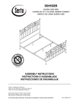
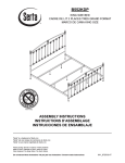
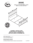
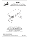
PR-25 Real Wood Audio Video Cabinet
ASSEMBLY INSTRUCTIONS
Patent Pending
The real hardwoods used in Bell'O furniture are naturally
beautiful. Some differences in wood grain are desirable
and expected. Please use only high quality wood furniture
polish to care for your cabinet.
PARTS LIST
PART DESCRIPTION
QUANTITY
A. CABINET TOP
1 PC
B. LEFT SIDE SUPPORT PANEL
1 PC
C. RIGHT SIDE SUPPORT PANEL
1 PC
D. UPPER INTERIOR SHELF
1 PC
E. MIDDLE INTERIOR SHELF
1 PC
F. BOTTOM SHELF
1 PC
G. TOP DOOR PANEL
1 PC
H. LOWER SHELF DIVIDER
2 PCS
I. UPPER SHELF DIVIDERS
2 PCS
J. CENTER SUPPORT LEG
1 PC
2
PARTS LIST (Continued)
PART DESCRIPTION
QUANTITY
K1. UPPER BACK PANEL
1 PC
K2. LOWER BACK PANEL
1 PC
L. LOWER CABINET DOORS
2 PCS
1. CAM LOCK PIN
18 PCS
2. CAM LOCK
18 PCS
3. 30MM DOWEL
32 PCS
4. 03X12MM SCREW
33 PCS
5. 50MM DOWEL
4 PCS
6. LEFT DRAWER HINGE
1 PC
7. UPPER DOOR KNOB
2 PCS
3
PARTS LIST (Continued)
PART DESCRIPTION
QUANTITY
8. 05/32" x 22MM SCREW
4 PCS
9. RIGHT DRAWER HINGE
1 PCS
10. HINGE PIN
2 PCS
11. 3.5 X 15MM SCREW
16 PCS
12. LOWER DOOR HINGE
4 PCS
13. LOWER CABINET KNOB
2 PCS
14. TOP SHELF SUPPORT ROD
1 PC
FOR YOUR SAFETY, PLEASE FOLLOW THESE PRECAUTIONS:
! ALWAYS REMOVE THE TV AND OTHER EQUIPMENT FROM THE FURNITURE PRIOR TO MOVING THE ASSEMBLED UNIT.
! BE CAREFUL WHEN MOVING THE ASSEMBLED FURNITURE AFTER THE SHELVES AND DOORS HAVE BEEN
INSTALLED, AND/OR WHEN THERE IS EQUIPMENT LOCATED ON OR IN THE FURNITURE AS THIS MAY CAUSE
THE SHELVES AND OTHER ITEMS TO BECOME UNSECURED AND FALL.
! WHEN IN USE, THIS FURNITURE MUST BE PLACED ON A FLAT, SOLID AND LEVEL SURFACE.
! DO NOT LEAN ON THE TV WHEN IT IS ON THE TV STAND.
! DO NOT CLIMB OR STEP ON THE STAND.
! DO NOT BANG OR PLACE YOUR OWN WEIGHT ON THE DOORS.
! DO NOT PLACE ITEMS ON THE SHELVES WHICH EXCEED THE MAXIMUM WEIGHT LIMITS OF 200 LBS. FOR TOP SHELF
AND 50 LBS. FOR EACH LOWER SHELF
4
ASSEMBLY INSTRUCTIONS
NOTE: 2 PEOPLE ARE RECOMMENDED TO ASSEMBLE THIS FURNITURE. THIS TABLE IS
CONSTRUCTED WITH REAL WOOD VENEER. TO AVOID DAMAGE DURING ASSEMBLY, IT
SHOULD BE ASSEMBLED ON A SOFT SURFACE.
Fig. 1
F
3
H
1. PLACE the bottom shelf (F) on edge. PLACE four smaller dowels (3) into the holes in the top
side of the bottom shelf as shown in Fig. 1. PLACE the edge of one of the dividers (H) onto
the dowels, with the FRONT arrow facing the front of the shelf (the edge without the cut out
slots) as shown.
5
Fig. 2
5
E
F
H
2. PLACE four larger dowels (5) half way through the lower middle shelf (E), and PLACE
the ends of the dowels into the exposed edge of the divider (H) as shown in Fig. 2.
6
Fig. 3
5
H
E
3. PLACE the second divider (H) over the exposed ends of the dowels (5) on the opposite
side of the lower middle shelf (E) with the FRONT arrow facing the front of the shelf (the
edge without the cut out slots) as shown in Fig. 3.
7
Fig. 4
D
3
H
4. Place four smaller dowels (3) into the holes on the exposed edge of the divider (H).
Place the upper interior shelf (D) onto the dowels as shown.
8
Fig. 5
14
H
2
B
3
1
10
5. PLACE the left cabinet side (B) on a soft surface with the levelling foot facing the rear as shown.
A. SCREW two cam lock pins (1) into the upper and center cross frame, and three cam lock pins
(1) into the bottom cross frame. INSERT two smaller dowels (3) into each of the cross frames.
B. INSERT two cam locks (2) into the underside of each shelf panel (D), (E) and three cam locks
into the underside of the bottom shelf panel (F) as shown.
C. INSERT hinge pin (10) into the cabinet side above the top shelf as shown in Fig. 5.
D. With the arrows on the dividers (H) facing FORWARD, CAREFULLY ALIGN the assembled
interior shelves and dividers with cam lock pins and dowels on the cabinet side and SECURE
them together by turning the cam locks to tighten. DO NOT FORCE the pieces together.
Alignment may require some slight movement of the parts to get the proper fit.
E. INSERT the top shelf support rod (14) into the predrilled holes in the cabinet side (B) as shown.
9
Fig. 6
C
3
6. Placement of the right cabinet
side (C):
A. SCREW two cam lock pins (1)
into the upper and center cross
frame, and three cam lock pins
(1) into the bottom cross frame.
INSERT two smaller dowels (3)
into each of the cross frames.
10
1
G
2
B. INSERT two cam locks (2) into
the underside of each shelf
panel (D), (E) and three cam
locks into the underside of the
bottom shelf panel (F) as
shown.
C. CAREFULLY ALIGN and
PLACE the top door panel (G)
onto the cabinet side (B) so
that it is resting on the hinge
pin (10). INSERT the remaining
hinge pin (10) into the exposed
end of the top door panel as
shown in Fig. 6.
J
D
D. With the adjustable foot on the
cabinet side panel (C) facing
towards the rear, CAREFULLY
ALIGN the cabinet side panel
B
with the assembled interior shelves
and dividers and SECURE them
together by turning the cam locks to
tighten. DO NOT FORCE the pieces
together. Alignment may require some
slight movement of the parts to get the
proper fit.
E
F
E. SCREW the adjustable center leg (J) into the insert
located in the bottom of the cabinet.
10
Fig. 7
I
3
6
4
3
8
D
G
4
7
8
9
7
7. CAREFULLY TURN the partially assembled cabinet upright.
A. SCREW the LEFT drop down door hinge (6) and RIGHT door hinge (9) into the interior sides
of the cabinet using the small Philips head screws (4). NOTE: THE DOOR TENSION ON THE
HINGES CAN BE ADJUSTED BY TURNING THE KNOB LOCATED ON THE HINGE.
B. INSERT four smaller dowels (3) into the upper interior shelf (D). ALIGN and PLACE the two
upper cabinet dividers (I) onto the dowels as shown in Fig. 7.
C. ATTACH the two upper door knobs ( 7) to the drop down door using screws (8).
11
Fig. 8
A
3
1
1
2
3
I
2
B
C
8. SCREW two cam lock pins (1) into the tops of the cabinet sides (B) and (C).
A. PLACE two smaller dowels (3) into the tops of the cabinet sides, and the tops of the dividers (I).
B. PLACE two cam locks (2) into the interior of each cabinet side.
C. CAREFULLY ALIGN the cabinet top panel (A) with the top of the cabinet sides and dividers and
SECURE them together by turning the cam locks to tighten. DO NOT FORCE the pieces
together. Alignment may require some slight movement of the parts to get the proper fit.
12
Fig. 9
K1
K2
4
9. Working from the rear of the cabinet, SCREW two rear panels (K1) and (K2) to the cabinet using
screws (4). NOTE: THE REAR PANELS ARE MADE TO BE SNUG. DO NOT FORCE OR
BEND THE PANELS MORE THAN VERY SLIGHTLY IF NEEDED.
13
Fig. 10
12
L
11
12
11
11
13
8
8
Ensure table is
level by adjusting
rear legs (J). This
will also aide in
leveling the doors.
13
L
10. SCREW the lower door hinges (12) to the interior of the cabinet using screws (11).
A. ATTACH the cabinet doors (L) to the hinges (12) using screws (11).
B. ATTACH the lower cabinet knobs (13) to the doors using screws (8).
14
Fig. 11:
Aligning the Doors
11. ALIGN the doors by adjusting the screws on the insides of each hinge (11) using the supplied
screwdriver tool as shown.
15
Warranty
One (1) Year Limited Warranty
All Bell’O International products are warranted, with the exception of glass, to the original purchaser at the time of
purchase and for a period of one (1) year thereafter. Glass is warranted to the original purchaser at the time of
purchase and for a period of thirty (30) days thereafter. Warranty is only valid in the United States of America.
In order to provide you with timely assistance, please thoroughly inspect your furniture for missing or defective parts
immediately after opening the carton. To receive replacement or missing part(s) under this warranty, go to our
website at www.bello.com or call our Customer Service Department at 1-888-235-7646. Please have the model
number and part number(s) for reference. You will also need your sales receipt or other proof of purchase.
Replacement part(s) will be shipped to you at no charge with Bell’O International assuming all shipping and handling
expense.
We warrant to you, the original purchaser, that our furniture and all of its parts and components are free of defects in
material or workmanship. "Defects", as used in this warranty, is defined as any imperfections that impair the use of
the furniture or product.
Our warranty is expressly limited to the replacement of furniture parts and components. For one (1) year after the
date of purchase, Bell’O International will replace any part described on the enclosed furniture parts list that is
defective in material or workmanship.
This warranty applies under conditions of normal use. Our furniture products are not intended for outdoor use. The
warranty does not cover: 1) defects caused by improper assembly or disassembly; 2) defects caused by shipping,
claims for damage during transit to you should be placed immediately by you to the transportation company;
3) defects occurring after purchase due to product modification, intentional damage, accident, misuse, abuse,
negligence or exposure to the elements; 4) cosmetic damage and 5) labor or assembly costs.
There are no warranties, express or implied, including without limitation merchantability or fitness for particular use,
except as (i) contained herein or (ii) required by applicable law in the state whose law governs (which shall be New
Jersey absent controlling law imposing the law of another state in lieu thereof as governing law). All warranties of
whatsoever derivation shall be limited to the term set forth above, unless otherwise required by applicable law.
Manufacturer’s employees or representatives’ … ORAL OR OTHER WRITTEN STATEMENTS DO NOT CONSTITUTE
WARRANTIES, shall not be relied upon by Buyer, and are not a part of the contract for sale or this limited warranty.
Except as provided herein, Bell’O International shall have no liability or responsibility to the purchaser or any other
person or entity with respect to any liability, loss or damage caused directly or indirectly by use of the product,
including, but not limited to, any incidental or consequential damages. Some states do not allow limitation on how
long an implied warranty can last or the exclusion of limitation of incidental or consequential damages, so the above
limitation and exclusion may not apply to you.
This warranty gives you specific legal rights. You may also have other rights, which vary from state to state.
BELL'O INTERNATIONAL CORPORATION, 711 Ginesi Drive, Morganville, NJ 07751-1235
Phone: (732) 972-1333 Fax: (732) 536-6482 Web: www.bello.com E-mail: [email protected]