1
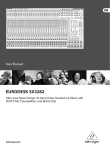
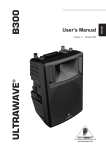
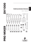
ENGLISH User Manual Pro Mixer DX2000USB Professional 7-Channel DJ Mixer with infinium “Contact-Free” VCA Crossfader, USB/Audio Interface and Massive Software Bundle Thank you The DX2000USB is a multi-functional stereo mixer designed for all applications where pre-recorded music is mixed and played. It is equally useful at home, in dance clubs, personal DJ setups and broadcast studios. It has two mono mic channels and five stereo music channels, plus USB input/output. The mic channels may be routed to the main mix directly. Music channels, on the other hand, must be assigned to one of two stereo submixes, called X and Y. A super-smooth user-definable VCA crossfader ultimately controls the blend of X and Y being sent to the main mix. behringer.com Table of Contents Thank you...................................................................... 1 Important Safety Instructions.................................... 2 1. Pro Mixer DX2000usb............................................ 3 2. Mono Input Channel............................................... 4 3. Stereo Input Channel.............................................. 5 4. Talk Over................................................................... 6 5. Master Audio Outputs............................................. 6 6. Headphones, Monitors & Pfl................................ 8 7. Sub Bass.................................................................... 9 8. Controlling External Devices.................................. 9 9. Connections.............................................................. 9 10. Crossfader Adjustment....................................... 13 11. Specifications....................................................... 14 Limited Warranty........................................................ 15 Legal Disclaimer......................................................... 16 Pro Mixer DX2000USB User Manual ENGLISH 3 Important Safety Instructions [7] Do not block any ventilation openings. Install in accordance with the manufacturer’s instructions. EN [8] Do not install near any heat sources such as radiators, heat registers, stoves, or other apparatus (including amplifiers) that produce heat. * [9] Do not defeat the safety purpose of the polarized or grounding- Terminals marked with this symbol carry electrical current of sufficient magnitude to constitute risk of electric shock. Use only high-quality commercially-available speaker cables with ¼" TS plugs pre-installed. All other installation or modification should be performed only by qualified personnel. * ! This symbol, wherever it appears, alerts you to important operating and maintenance instructions in the accompanying literature. Please read the manual. Caution the manufacturer. [12] Use only with the cart, stand, tripod, bracket, or table specified by the manufacturer, or sold with the apparatus. When a cart is used, use caution when moving the cart/apparatus combination to avoid injury from tip-over. [13] Unplug this apparatus during lightning storms or when unused for long periods of time. required when the apparatus has been damaged in any way, such as power supply cord or plug is damaged, liquid has been spilled or objects have fallen into the apparatus, the apparatus has been exposed to rain or moisture, does not operate normally, or has been dropped. [15] The apparatus shall be connected to a MAINS socket outlet Caution To reduce the risk of fire or electric shock, do not expose this appliance to rain and moisture. The apparatus shall not be exposed to dripping or splashing liquids and no objects filled with liquids, such as vases, shall be placed on the apparatus. ! [11] Use only attachments/accessories specified by [14] Refer all servicing to qualified service personnel. Servicing is To reduce the risk of electric shock, do not remove the top cover (or the rear section). No user serviceable parts inside. Refer servicing to qualified personnel. ! [10] Protect the power cord from being walked on or pinched particularly at plugs, convenience receptacles, and the point where they exit from the apparatus. This symbol, wherever it appears, alerts you to the presence of uninsulated dangerous voltage inside the enclosure - voltage that may be sufficient to constitute a risk of shock. ! type plug. A polarized plug has two blades with one wider than the other. A grounding-type plug has two blades and a third grounding prong. The wide blade or the third prong are provided for your safety. If the provided plug does not fit into your outlet, consult an electrician for replacement of the obsolete outlet. Caution These service instructions are for use by qualified service personnel only. To reduce the risk of electric shock do not perform any servicing other than that contained in the operation instructions. Repairs have to be performed by qualified service personnel. [1] Read these instructions. [2] Keep these instructions. with a protective earthing connection. [16] Where the MAINS plug or an appliance coupler is used as the disconnect device, the disconnect device shall remain readily operable. 1. Pro Mixer DX2000usb 1.1 Highly accurate main and PFL peak—reading bargraph meters The main output level is constantly monitored by a pair of highly accurate main bargraph meters [38] . In addition, all channels have PFL (Pre-Fader-Listen) [13] . This means that you can see (on a separate PFL bargraph meter [39] ) and hear (on your headphones and/or monitors) the music you are about to play without disturbing the mix—essential if you want to come in at the same level and in time with the music currently playing. All professional DJ’s strive to do this, often overlapping two tracks, or slowly crossfading between them. (These and other DJ mixing tricks will be explained elsewhere in this manual.) [3] Heed all warnings. 1.2 How will you use your DX2000USB? [4] Follow all instructions. Your DX2000USB is a creative instrument. Learn to play it well. If possible, experiment with it “off-line”—before you use it in earnest in a club or studio. It offers you many creative music mixing possibilities, with its ultra DJ-friendly [5] Do not use this apparatus near water. [6] Clean only with dry cloth. control surface. In addition, many special features have been included to enhance the flexibility and ease of operation of your mix. For example, the adjustable TALK OVER feature can automatically and temporarily reduce the music level while you are speaking. We have given particular attention to metering your music with PFL offered on every channel. In addition, all channels have signal present and clip LEDs constantly monitoring input levels. You will also see virtually every switch on your DX2000USB has an associated status LED to let you know when it is engaged. Just another way in which we try to make life easier for you, the DJ. It is true that not all the features of the DX2000USB are relevant to every application. For example, the TRACK START [20] buttons buttons may be extraneous to the needs of the vinyl DJ. Nonetheless, the superior quality of all of the features of your DX2000USB means you will be well equipped for any situation. 1.3 PSU (Power Supply Unit) Please connect the IEC cable to the power socket [72] on the back panel of your mixer. ENGLISH Pro Mixer DX2000USB User Manual 2 ENGLISH 1.4 Rack mounting the DX2000USB Your DX2000USB is shipped with optional rack ears. If you want to make your DX2000USB a desktop mixer, loosen the screws from the side panels and remove the rack ears (note that there is a left and a right one). 1.5 Warranty Please register your mixer on our website at behringer.com to become eligible for our extended warranty. The serial number [71] can be found on the rear panel. 1.6 Packing Your BEHRINGER PRO MIXER DX2000USB was carefully packed in the factory and the packaging was designed to protect the unit from rough handling. Nevertheless, we recommend that you carefully examine the packaging and its contents for any signs of physical damage, which may have occurred in transit. ◊ If the unit is damaged, please do not return it to us, but notify your dealer and the shipping company immediately, otherwise claims for damage or replacement may not be granted. Shipping claims must be made by the consignee. 2. Mono Input Channel Plug a mic or line source (tape, CD player etc.) into the appropriate MIC [52] or LINE [51] input. Speak or play music at typical volume to check out and set up the channel. ◊ Mic and line inputs are on balanced XLR and ¼" jacks respectively. Balanced operation gives best noise performance. Unbalanced microphones need to have XLR pins 1 and 3 shorted. Any Line source will work perfectly well if a mono jack is used, or the ring and barrel of a TRS jack are shorted (see chapter 10 “CONNECTIONS”). 2.1 Input selection Inputs are on the back panel. Your input source is selectable between MIC and LINE by a switch [1] . A pair of associated LEDs [2] lets you know which input is selected. 2.2 Gain setting ◊ Gain is dependent on EQ. Set up your EQ before fine-tuning gain. If you re-EQ, also re-check gain. 2.2.1 Quick way Channel input level is continuously monitored by a pair of LEDs [3] . As long as the SIG. LED is flickering and the CLIP is not, the gain is reasonable. Mic channel input level can be continuously adjusted by the GAIN knob [4] (from +10 to +60 dB; Mic signals are low, therefore they need to be heavily pre-amplified). CLIP lets you know if you overload the channel (it lights at +18 dB). ◊ SIG. lets you know if a signal is present (it only responds to bass frequencies). That’s why you can use it to keep an eye on the beats. ◊ If you are using a mono line source in a mic channel, the gain structure is comparable to that on a stereo music channel, albeit 20 dB more sensitive. (from - 10 to + 40 dB ; = 20 dB pad on mic input) 2.2.2 Gain setting by using PFL Pre-Fader-Listen is the professional way to set gain. Hit the PFL button [13] to temporarily send the channel signal to the PFL bargraph meter [39] . Adjust the GAIN control until the bargraph meters are in the yellow (0 dB) but not the red (Clip). Once gain has been set for a channel, release its PFL button. Pro Mixer DX2000USB User Manual 5 2.5 Output Mic channel output is fed directly into the main mix, not via the X and Y subgroup channels. Level is controlled by a precision 100 mm fader [14] , while stereo position is set by the PAN control [10] . The channel signal is sent to the mix by depressing the CHANNEL ON switch [12] . A LED indicator illuminates when the channel is on. (Channel on is the inverse of the more traditional channel mute found on standard recording consoles). ◊ The mic channels are routed to the RECORD OUT jacks [66] on the rear panel of the DX2000USB, but not to the LINE OUT jacks [22] situated to the left of the main meters. ◊ You will usually want to PFL only one channel at a time, otherwise the PFL meter reading will be meaningless. ◊ The faders used are special high-quality true-log faders. These give ultra-smooth operation even at low levels, on par with those used in very expensive studio consoles. 2.3 Insert point 2.6 Effects Situated on the rear of the console, mic channels have insert points [50] on TRS jacks. (These are post-gain and pre-EQ). You can use these combined input/output sockets to put a compressor, gate or any other signal processor(s) in line with your microphone (see chapter 10 “CONNECTIONS”). You can patch a mono or stereo outboard effects processor into your DX2000USB via the SEND [53] and RETURN [54] jacks on the back panel. Now you can add effects to your voice instantly simply by punching the illuminated EFFECT button [9] . The effect send level is dependent on the fader setting. Adjust the desired amount of effect (from -oo to +30 dB) by the FX RETURN knob [42] to the right of the bargraph meters. ◊ Compressors can help even out voice volume, adding loads of energy, but they can also cause feedback problems if over-used. Noise gates shut off mics automatically when not in use—useful for keeping out music spillage which can muddy the sound of your mix. Often a compressor/gate combination is best. Check out the excellent BEHRINGER range of interactive dynamics products. ◊ Set your effects unit input level so that the input meter reading (if there is one) is healthy when you are sending a typical signal to it. Too low a level will mean too much hiss on your effects return, too high and you’ll get distortion. 2.4 Equalizer 3. Stereo Input Channel The mic channel EQ section comprises three control knobs and one switch. Depressing the LOW CUT switch [5] rolls off the bass end (-18 dB/oct @ 75 Hz). We recommend using this feature with microphones to eliminate “popping” and handling noise. Where loud music is playing, LOW CUT also helps to avoid bass feedback. Separate controls cut and boost HIGH [6] , MID [7] and LOW [8] frequencies respectively. Use EQ creatively to sweeten the sound of your microphone, or defensively to help cut feedback (see below for EQ specifications). Plug a phono (turntable) or line source (CD player etc.) into the appropriate PHONO/LINE [59] or CD [58] input. Play music at a typical volume to check out and set up the channel. Press the PHONO/LINE button if you would like to use the PHONO/LINE jacks for a line-level source instead of a turntable. EQ Frequency Range Centre High Shelving EQ 10 kHz +/– 12 dB OFF Mid Peaking EQ 750Hz +/- 8 dB OFF Low Sheiving EQ 50Hz +/– 12 dB OFF Tab. 2.4: Equalizer of the mono input channels ◊ If you are serious about your mic channel, and want to really kill feedback, you can patch our FEEDBACK DESTROYER PRO DSP1124P across the channel insert point at the rear of the console. It is ideal for this purpose. 3.1 Input selection Inputs are on the DX2000USB’s back panel. Your input source is selectable between a pair of stereo inputs by the INPUT switch [1] at the top of the channel strip. An associated pair of LEDs [2] lets you know which input is selected. The choice of inputs depends on which of channels 3 - 7 you are looking at. The mixer is set up as follows: Channel Input 1 Input 2 3 PHONO/LINE 1 CD 1 / USB 4 PHONO/LINE 2 CD 2 5 PHONO/LINE 3 CD 3 6 LINE 1 CD 4 7 LINE 2 CD 5 Tab. 3.1: Stereo channel configuration ◊ Never patch line level devices into your highly sensitive phono inputs. Phono cartridge output is measured in millivolts. Line level signals are of the order of magnitude of a volt. With line levels you are looking at a signal up to 100 times more powerful than the phono pre-amplifier is designed to handle! Press the PHONO/LINE button to allow the PHONO/LINE jacks to operate at line-level. ◊ If for some reason your turntable has a built-in RIAA pre-amp, you should patch it into a line level input. ◊ A mix could include three turntables (channels 3 - 5) and two samplers for creative DJ work, or four CD/cart players plus a stereo tape recorder for a broadcast studio. In fact any line level signal could be patched into any line-level input. 3.2 Gain setting ◊ Gain is dependent on EQ. Set up your EQ before fine-tuning gain. 3.2.1 Quick way Channel input level is continuously monitored by a pair of LEDs [3] . CLIP lets you know if you’re about to overload the channel (it lights at +18 dB). The SIG. LED only responds to bass frequencies and is perfectly suited to keep an eye on the beats. As long as the signal LED is flashing on the beat (and the CLIP LED isn’t) you can be sure the gain is reasonable. Do this for all music channels. Channel gain can be continuously adjusted by the GAIN knob [4] (from -20 to +20 dB). ◊ If you are in the habit of slamming the channel faders all the way up (+6 dB), try to keep your MAIN faders at a compensatory -6 dB to make sure you don’t risk distortion. At this level PFL and MAIN meters should show the same level (check this by engaging PFL on the channel currently playing), allowing easy comparison between outgoing (playing) and incoming (cueing) tracks. Keep an eye on the output meters—red spells trouble. Remember—distortion is not volume, and any distortion introduced before the power amplifiers and speakers will worsen your sound and cause amps and speakers to clip sooner. 3.2.2 Gain setting by using PFL Pre-Fader-Listen is the professional way to set gain, and we always recommend you do it if you have the time. Hit the PFL button [13] to temporarily send the channel signal to the PFL meter [39] . Adjust GAIN until the PFL meter is hitting the yellow (up to +10 dB) but not the red (clip). Once gain has been set for a channel, release its PFL button. ◊ Normally you will want to PFL only one channel at a time. This might not be true if you are layering tracks, and/or using “Permanent PFL”—see the chapter 7 “HEADPHONES, MONITORS & PFL”. Also note that the mono PFL meter is a sum of L and R channel signals. ENGLISH Pro Mixer DX2000USB User Manual 4 ENGLISH 3.3 Equalizer The channel EQ section comprises three control knobs and two switches. The EQ ON [16] switch activates the tone controls which enable cut and boost of HIGH [6] , MID [7] and LOW [8] frequencies respectively (see below for specs.) EQ can sweeten or effect a track, with the fading out and in of frequency bands being very popular. EQ Frequency Range Centre High Shelving EQ 15 kHz +6/-18 dB OFF Mid Peaking EQ 1.4 kHz +6/-25 dB OFF Low Sheiving EQ 50Hz +6/-25 dB OFF Tab. 3.2: Equalizer of the stereo channels ◊ EQ is particularly useful if two or more music tracks are playing together, as frequencies often clash. Low frequencies in particular can phase and cancel, causing uneven bottom-end response. The trick is to cut the bass from all but one track playing. You can roll off the bass by turning LOW fully counterclockwise. 3.4 Output Channel level is controlled by a precision stereo 100-mm fader [14] . ◊ The faders used are high-quality true-log faders. These give ultra-smooth operation even at low levels, on a par with those used in the most expensive studio consoles. Press the CROSSFADER switch [17] to send the channel signal to either of the two stereo submixes, which we call X and Y. The ASSIGN button [18] selects between these two submixes, and a pair of LEDs [19] clearly show you which of X or Y is currently selected per channel. The X and Y mixes are then routed to opposite ends of the main crossfader [33] . ◊ You can immediately tell if any channel is switched on (CROSSFADER switch depressed) by looking at the master ASSIGN X and ASSIGN Y [36] indicators situated under the crossfader. 4. Talk Over Let’s say you are talking over a music intro. You would almost certainly want to attenuate the music while you speak. The DX2000USB talk over system does this for you— automatically. Depressing the TALK OVER button [11] on a mic channel engages the talk over system. You can leave this button down all the time—it will not affect the music unless you speak into the mic, provided you set the system up correctly. How do you do this? If you look to the left of the main bargraph meters you will see three rotary controls and two LEDs. These are the master talk over adjustments you will want to make. Once you have set them up for your system you will probably not have to alter them unless something else is changed. SENSITIVITY [23] sets the speech level threshold at which attenuation (also called gain reduction) kicks in once talk over is activated by a mic channel signal. TIME [24] controls the rate at which music volume recovers after a mic channel signal has activated the automatic music level reduction process. DAMPING [25] allows you to adjust the depth of music attenuation triggered by the mic channel signal. To set up these controls properly, first turn DAMPING full on (MAX). Set up the gain on your mic channel using PFL. Now adjust SENSITIVITY until the music is always attenuated by a voice signal. (Attenuation is at MAX to enable you to hear this adjustment as clearly as possible.) ◊ Take care to ensure that SENSITIVITY is not set too high, otherwise spill from loudspeakers into the mic could trigger the talk over system, and the music volume will just keep going up and down! (You have set up an intermittent negative feedback loop.) Once SENSITIVITY has been set so that talk over is only being activated by speech, it’s time to fine-tune the system with the other two controls again, according to taste. Twin LEDs let you know how your talk over system is behaving. When DAMP [27] is lit, your music is being automatically attenuated. ON [26] lets you know that one or both mic channels have talk over engaged. ◊ If two mics are being used, set SENSITIVITY with both mic channels switched on. ◊ Talk over could just as easily be used for MC-ing. It might not however be appropriate for rapping, which takes place alongside rather than over the music, unless the damping effect is set to be quite subtle. 5. Master Audio Outputs 5.1 Crossfader The heart of your music mix is the horizontally-mounted infinium optical crossfader [33] , which controls the blend of the X and Y mixing channels. When set fully to the left, only X is heard in the mix, and vice versa. We know how much you rely on this, and for that reason we have not only ensured that it is incredibly durable and smooth-acting. We also allow you to tailor its response to your “feel” by means of a simple adjustment (see chapter 11 “CROSSFADER ADJUSTMENT”). The crossfader is most often used to fade one track into another during a DJ mix. ◊ If you are bringing in an intro over an outro, there will be a time when you want to hear both tracks at full volume. Simply pause your crossfader in the middle position until you are ready to fade out the outgoing track. ◊ The crossfader is actually a sophisticated VCA controller. Its ultra-high quality design means that you can expect nearly endless operations without failure. And even if the fader does get something nasty poured Pro Mixer DX2000USB User Manual over it by mistake (please don’t do this!) the quality of your music should be unaffected. This is because no audio signal actually passes through your crossfader, unlike on many other DJ mixers. ◊ You can immediately tell if any channel is switched on (CROSSFADER switch depressed) by looking at the master ASSIGN X and ASSIGN Y indicators [36] situated under the crossfader. 5.2 Transforming with punch and cut Transforming is a DJ term used to describe the chopping up of sound to create dramatic effects. Traditionally this is done by rapidly moving a crossfader to give a stuttering or “gated” effect, either between two music sources, or one source and silence. Another DJ trick is to use the channel faders or channel on buttons to chop one music track over another. These methods are still valid, but if you are looking for instantaneous transforming action, check out our ergonomic alternative—a pair of big assignable PUNCH/CUT buttons. We are sure you will grow to love their speed and ease of operation. Punch and cut are two transform modes selectable by the TRANSFORM MODE button [48] . A pair of LEDs [49] lets you know whether PUNCH or CUT is active. The X and Y PUNCH/CUT buttons [34] and [35] are ergonomically situated by the crossfader with which they are designed to work. CUT mode enables the big buttons to be used as mutes for interesting gating effects, temporarily silencing the X or Y output. In PUNCH mode the X button [34] introduces the X signal to the mix, while the Y button [35] brings in the Y signal. This means you can add in bits and beats from X on top of Y and vice versa, opening up your scope for creative mixing. ◊ This is the first time we have come across any really BIG buttons on the DX2000USB. At this point it’s worth pointing out that all the smaller switches on your DX2000USB are latching. This means they stay down until you hit them again. Big buttons are all non-latching, or momentary in operation. This means that they are only active when your finger (or other appendage) is actually holding them down, like the keys on a MIDI keyboard. These are ideal for executing transformations, as you will very quickly find as you get into using your DX2000USB. ◊ Try running a rhythm track through X (crossfader fully to the left). Now use the Y button in PUNCH transform mode to manually chop in a sustained signal like orchestral music, ambient sounds, noise, whatever. ◊ As well as using the X - Y crossfader to select / fade between X and Y you can also use it to blend X and Y together, by simply leaving it somewhere in the middle. Now you can use the big buttons in CUT mode to chop between X and Y for more creative music gating effects. ◊ You can send more than one channel to either X, Y or both. In practice you will usually only send one at a time, but if you are layering tracks you might want to 7 send more. Also you can crossfader between channels assigned to the same side of the crossfader using the 100 mm channel faders. 5.3 Main/tape outputs Level to the main outputs (Max. output +28 dBu balanced, +22 dBu unbalanced) is ultimately governed by a pair of precision 60 mm main faders [30] . This level is continuously monitored by the pair of highly accurate tri-colored bargraph meters [38] sited immediately above the output faders. The main outputs constitute a blend of X and Y, as well as channels not assigned to the crossfader, and the two mic channels, all covered previously in the manual, plus the stereo effects return. The main output also feeds the RECORD OUT jacks on the back of the console. ◊ The LINE OUT jacks on the top of the console are taken directly from the output of the crossfader. This mix does not include the mic channels 1 and 2. ◊ Never connect to both sets of LINE IN/OUT jacks (see chapter 10 “CONNECTIONS”). 5.4 Main boost and main dim MAIN BOOST [28] and MAIN DIM [29] are big non-latching buttons acting on the main outputs, temporarily boosting (by +4 dB) and cutting (by -20 dB) volume. ◊ MAIN DIM could be used for audience sing-along bits. Or you could use MAIN BOOST to emphasize the beats etc. ◊ MAIN BOOST should not be applied for more than just spot effects, as you will probably stress the sound system, or simply cause the limiters to come in harder. 5.5 Zone The ZONE stereo output [69] is a second main mix output with its own totally independent ZONE LEVEL control [41] . This can be used for feeding the mix into a separate sound system such as DJ foldback, or another room or area in a dance club. 5.6 Effect return A line-level stereo effect RETURN [54] (Max. gain 30 dB) feeds directly into the mix, level being adjusted by the FX RETURN knob [42] . This input is designed to accept the output from a mono or stereo effects unit (see chapter 10 “CONNECTIONS”). It could also be used to return another stereo music source such as DAT or mini disc if five stereo channels are not enough for your music needs. 5.7 USB connection The DX2000USB has built-in USB connectivity, allowing stereo signals to be sent to and from the mixer and a computer. The audio sent from the mixer to a computer is identical to the RECORD OUT signal. Audio being sent from a computer to the DX2000USB can be selected with the Channel 3 INPUT button. ENGLISH Pro Mixer DX2000USB User Manual 6 ENGLISH Connect a USB type B plug into the USB jack on the mixer, and the other end into a free USB port on your computer. There are no required drivers, but we recommend that PC users install the included ASIO driver. The driver can also be downloaded from behringer.com. 6.2 Headphones—read carefully—this is tricky! 6. Headphones, Monitors & Pfl OPTION 1: 6.1 Monitoring A separate stereo MONITOR output [68] is provided. Level is controlled by a single 60 mm MONITOR stereo fader [32] . The monitor signal is taken directly from the main mix. Engaging PFL anywhere on the board changes the monitor source to PFL. ◊ Main fader adjustments will not affect the level of the monitor output—unlike on standard recording consoles where monitor follows the main faders. 6.1.1 PFL in the studio In a studio setup, the monitor output is normally sent to an amplifier driving a pair of speakers facing the operator. (The main output might feed a tape recorder (recording studio) or transmission line (broadcast studio)). In the studio environment, PFL (Pre-Fader-Listen) is the preferred way to set up an individual channel. Depressing a channel’s PFL button cancels the mix from the monitor output and replaces it with that channel’s signal. Now the DJ or engineer can hear in isolation what’s going on in one (or more) channel(s), via headphones or the monitor speakers. During PFL, channel level is sent to the PFL meter to enable accurate gain setting. 6.1.2 PFL in the club In a club, the main output would normally drive the house PA, while the monitor output could offer foldback into the DJ area, usually via a separate amp and speaker(s). In the club environment, things get messy. You can’t hear any sound in isolation, either on a foldback system or headphones, because both are to some extent drowned out by the main PA system. You should, however, be able to hear the PFL signal loud enough to detect the beat, cue starts etc. What you can’t do is to judge by ear exactly what level the next track will come in at. For that you must use your eyes and the highly-accurate bargraph meters. ◊ PFL is in stereo: if you PFL a stereo channel you will hear it in stereo even though there is only one PFL bargraph meter. If a mono channel is PFL-ed, you will hear it according to the position of the channel PAN. This is a professional feature and called “Solo-In-Place” in big recording consoles. Pro Mixer DX2000USB User Manual 9 The PHONES section lies to the far right hand side of the DX2000USB, below the headphones stereo jack socket [43] . PHONES LEVEL [45] controls headphones level. Right, that’s the easy bit explained. Now pay attention. The PHONES output can have as its source either PFL or Main mix selected by the MAIN/PFL switch [44] . When this switch is down, headphones follow the same logic as monitor, i.e. main mix unless any channel has PFL engaged. When it is up, headphones audition PFL only, i.e. if no channel’s PFL is engaged, the heaphones will fall silent. (NOTE: SPLIT switch is UP here) OPTION 2: Depressing the SPLIT switch [47] disables the PFL/MAIN switch, activating instead the BALANCE control [46] . The headphones mix is now in mono instead of stereo as previously, and BALANCE controls the blend of the PFL and MAIN mix signals. This gives you the interesting possibility of hearing both the outgoing (MAIN) and incoming (PFL) tracks simultaneously through a single output, via your headphones. The same signal can be heard at the monitor output so long as the PHONES TO MONITOR button [31] , sited above the MONITOR fader, is depressed. (PHONES TO MONITOR forces the monitor output to follow the headphones.) 6.3 Permanent PFL—using PFL as a listening subgroup We have seen that with both the PHONES TO MONITOR and PFL/MAIN switches depressed, your monitor output is always looking at PFL, not switching automatically between PFL and the main mix. Now you can actually use the stereo PFL bus as a subgroup with its own stereo output (the MONITOR output). ◊ Another way to keep the monitors fixed on PFL is to make sure a PFL button is always left engaged somewhere on the desk. You could simply leave a PFL button depressed on an unused, unassigned channel. If your channel fader is always brought up to +6 dB (i.e. full-on as per usual with you DJ types) then comparing PFL values will give a true indication of relative mix volume between tracks. Now all you have to do in order to achieve a totally professional-sounding volume-consistent mix is to adjust each successively incoming track’s gain until the PFL meter is hitting 0 dB (or whatever level you think you can get away with) before you bring it in with the crossfader. It’s that simple. Try it ... 7. Sub Bass The sub bass output [63] on the back panel comes with two rotary controls, one for output LEVEL [62] (max. +22 dBu) and another for adjusting the crossover frequency of the low pass filter, CROSSOVER FREQUENCY. [61] (low pass filter variable from 30 Hz to 200 Hz). This can be used to drive a very low frequency sound system in a studio or club to provide added bottom end. ◊ Sub bass units are often useful in small studios where there is no room for large extended-range monitors in front of the mixer. channel immediately above it. Otherwise things could get very confusing! Please refer to the specifications of the equipment you want to connect. 8.3 Sound-to-light A mono audio output [60] is provided for connection to lighting controllers with a sound-to-light facility. Connection is via a standard ¼" jack on the back panel. Sensitivity is conveniently adjustable from the DX2000USB by the LIGHT LEVEL knob [40] to the left of the bargraph meters. Too high, and the lights will stay on, too low and they won’t flash at all. Adjust LIGHT LEVEL until lights flash in time with the music. 8. Controlling External Devices 9. Connections 8.1 Desk lamp 9.1 PRO MIXER DX2000USB connections A connector [37] for an optional standard 12 V working light is offered, immediately above the bargraph meters. You should only use 5 Watt lights. Follow us on a walk along the rear panel of your PRO MIXER, starting left: 8.2 Remote control of audio devices We have not yet mentioned the big non-latching TRACK START buttons [20] immediately below the faders on channels 3 to 7. These have nothing to do with the audio side of your desk. They are REMOTE CONTROL buttons for interfacing with certain audio sources such as CD players, CART machines etc. which have remote jacks built into them. Please refer to the manufacturer’s specifications to see if your equipment conforms to this protocol. If it does, connection to the DX2000USB is by simple jack leads [55] on the rear panel. Please ensure that your equipment’s remote control output does not exceed 30 V DC/50 mA (This is unlikely!). The advantages of REMOTE CONTROL are purely ergonomic—you don’t have to stretch over the desk to bring in an audio file, jingle or music CD in on cue. For clarity of function it is best to associate each REMOTE button on the DX2000USB with the device supplying audio to the stereo [50] Channel inserts. For inserting into the channel signal, pre-EQ and pre-fader. Unbalanced, send and return on a single ¼" jack socket, wired tip = send (out), ring = return (in) and sleeve = ground/screen. [51] Line input. Balanced ¼" jack socket, wired tip = hot (+ve), ring = cold (-ve) and sleeve = ground/screen. [52] Mic input. Balanced XLR, wired pin 1 = ground/screen, 2 = hot (+ve) and 3 = cold (-ve). [53] (Aux) Send. Unbalanced ¼" jack socket, wired tip = signal and sleeve = ground/screen. [54] (Aux) Return. Unbalanced ¼" jack sockets, wired tip = signal and sleeve = ground/screen. [55] Remote control. ¼" jack socket. [56] Line Input (Input 7). Unbalanced ¼" jack sockets, wired tip = signal and sleeve = ground/screen. [57] CD inputs. RCA sockets. [58] CD inputs. RCA sockets. ENGLISH Pro Mixer DX2000USB User Manual 8 ENGLISH [59] Phono/Line inputs. RCA sockets. [60] Light out. Unbalanced ¼" jack socket, wired tip = signal and sleeve = gound/screen. [63] Sub bass out. Balanced XLR, wired pin 1 = ground/screen, pin 2 = hot (+ve) and pin 3 = cold (-ve). [70] Monitor outputs. Balanced XLR, wired pin 1 = ground/ screen, pin 2 = hot (+ve) and pin 3 = cold (-ve). [72] IEC socket. For connecting the mixer a standard IEC cable. Always connect the mixer to a wall outlet before engaging the POWER switch. [64] Main inserts. For inserting into the main mix signal. Unbalanced, send and return of one channel on a single ¼" jack socket, wired tip = send (out), ring = return (in) and sleeve = ground/srceen. [74] USB input. Accepts a standard Type B USB cable for stereo input/output connection with a computer. [65] Main outputs. Balanced ¼" jack sockets, wired tip = hot (+ve), ring = cold (-ve) and sleeve = ground/screen. [22] Line out (without voice). RCA sockets. [66] Record out (with voice). RCA sockets. [67] Main outputs. Balanced XLR, wired pin 1 = ground/ screen, pin 2 = hot (+ve) and pin 3 = cold (-ve). [68] Monitor outputs. Unbalanced ¼" jack, wired tip = signal and sleeve = ground/screen. [69] Zone outputs. Unbalanced ¼" jack, wired tip = signal and sleeve = ground/screen. And on the front panel: [21] Line in. RCA sockets. [43] Phones. ¼" jack socket, wired tip = left signal, ring = right signal and sleeve = ground/screen. ◊ Please ensure that only qualified persons install and operate the PRO MIXER DX2000USB. During installation and operation the user must have sufficient electrical contact to earth. Electrostatic charges might affect the operation of the PRO MIXER DX2000USB! Pro Mixer DX2000USB User Manual 11 ENGLISH Pro Mixer DX2000USB User Manual 10 ENGLISH 9.2 Plug soldering guide You will need a lot of cables for different purposes—see the following figures to make sure you have got the right ones. Pro Mixer DX2000USB User Manual 13 10.2 Slope Balanced use with XLR connectors With the SLOPE potentiometer (VR44) you can adjust the fade over process of the both channels. Dependent on the setting of the SLOPE potentiometer there are the following volume curves: input Use custom-made RCA cables for all connections which use RCA sockets (centre post = signal (+ve) and sleeve = ground/screen). 1 = Ground / Shield 2 = hot (+ve) 3 = cold (-ve) output For unbalanced use pin 1 and pin 3 have to be bridged Fig. 10.1: Un-/balanced jack plugs and balanced XLR connectors Fig. 10.3: Insert send/return plug Fig. 11.1: Volume curve I (SLOPE potentiometer completely left) 10. Crossfader Adjustment On the main motherboard you can find two potentiometers, which you can adjust with a little screwdriver. These potentiometers are identified as OVERLAP and SLOPE. You can unscrew the bottom of your mixer to reach the main motherboard. ◊ Please be aware that the BEHRINGER warranty becomes discretionary when you start disassembling your DX2000USB! Don’t even think of it, if you make much of your warranty privileges. Sorry, but we have to mention this. 10.1 Overlap Fig. 10.2: Headphones connector With the OVERLAP potentiometer (VR43) you can adjust the increase or decrease in dB, which is conducted when the crossfader is located in the middle position. Ex works this value is adjusted at -3 dB and should not be modified. This guarantees a constant volume across the entire fader path. Fig. 11.2: Volume curve II (SLOPE potentiometer completely right) ENGLISH Pro Mixer DX2000USB User Manual 12 ENGLISH Mic input Gain Frequency response THD E lectronically balanced, discrete input configuration +10 to +60 dB 10 Hz to 80 kHz, +/-3 dB 0.08 % typ. @ -30 dBu, 1 kHz -10 to +40 dB 10 Hz to 80 kHz, +/-3 dB 0.08 % typ. @ -10 dBu, 1 kHz S/N ratio 85 dB, unweighted EQ Low Mid High Low cut +/-12 dB @ 50 Hz +/-8 dB @ 750 Hz +/-12 dB @ 10 kHz 75 Hz, 18 dB/oct Stereo Input Channels Phone/Line/CD input Unbalanced input Gain Line/CD Phone +17/-20 dB +17/-20 dB Frequency response Line/CD Phone 10 Hz to 130 kHz, +/-3 dB 20 Hz to 20 kHz, RIAA THD Line/CD Phone 0.05 % typ @ 0 dBu, 1 kHz 0.1 % typ @ -40 dB, 1 kHz S/N ratio Line/CD Phone -82 dB, unweighted -78 dB, unweighted Kill EQ Low Mid High +6/-25 dB @ 50 Hz +6/-25 dB @ 1.4 kHz +6/-18 dB @ 15 kHz Connectors § 1 Warranty [2] This limited warranty does not cover the product if it has been electronically or [1] This limited warranty is valid only if you purchased the product from a BEHRINGER mechanically modified in any way. If the product needs to be modified or adapted in order to comply with applicable technical or safety standards on a national or local level, in any country which is not the country for which the product was originally developed and manufactured, this modification/adaptation shall not be considered a defect in materials or workmanship. This limited warranty does not cover any such modification/adaptation, regardless of whether it was carried out properly or not. Under the terms of this limited warranty, BEHRINGER shall not be held responsible for any cost resulting from such a modification/adaptation. Zone out Jack 0 dB (max.10 dB gain) Insert send 0 dB Insert return 0 dB authorized dealer in the country of purchase. A list of authorized dealers can be found on BEHRINGER’s website behringer.com under “Where to Buy”, or you can contact the BEHRINGER office closest to you. Effect send 0 dB [2] BEHRINGER* warrants the mechanical and electronic components of this product USB Line input Gain Frequency response THD Audio Stereo In/Out Connector Type B Sample rate 48 kHz Power Supply Mains Voltages Power consumption Fuse (100 - 230 V ~, 50/60 Hz) Mains connector 100 - 240 V ~, 50/60 Hz 40 W T 1.6 A H 250 V Standard IEC receptacle to be free of defects in material and workmanship if used under normal operating conditions for a period of one (1) year from the original date of purchase (see the Limited Warranty terms in § 4 below), unless a longer minimum warranty period is mandated by applicable local laws. If the product shows any defects within the specified warranty period and that defect is not excluded under § 4, BEHRINGER shall, at its discretion, either replace or repair the product using suitable new or reconditioned product or parts. In case BEHRINGER decides to replace the entire product, this limited warranty shall apply to the replacement product for the remaining initial warranty period, i.e., one (1) year (or otherwise applicable minimum warranty period) from the date of purchase of the original product. [3] Upon validation of the warranty claim, the repaired or replacement product will be returned to the user freight prepaid by BEHRINGER. [4] Warranty claims other than those indicated above are expressly excluded. Physical Dimensions 2 3/8 / 6 x 17 ¼ x 14" / 61 mm / 152.4 x 440 x 355.5 mm Weight 14.3 lbs / 6.5 kg PLEASE RETAIN YOUR SALES RECEIPT. IT IS YOUR PROOF OF PURCHASE COVERING YOUR LIMITED WARRANTY. THIS LIMITED WARRANTY IS VOID WITHOUT SUCH PROOF OF PURCHASE. § 2 Online registration Please do remember to register your new BEHRINGER equipment right after your purchase at behringer.com under “Support” and kindly read the terms and conditions of our limited warranty carefully. Registering your purchase and equipment with us helps us process your repair claims quicker and more efficiently. Thank you for your cooperation! § 3 Return authorization number [1] To obtain warranty service, please contact the retailer from whom the equipment was purchased. Should your BEHRINGER dealer not be located in your vicinity, you may contact the BEHRINGER distributor for your country listed under “Support” at behringer.com. If your country is not listed, please check if your problem can be dealt with by our “Online Support” which may also be found under “Support” at behringer.com. Alternatively, please submit an online warranty claim at behringer.com BEFORE returning the product. All inquiries must be accompanied by a description of the problem and the serial number of the product. After verifying the product’s warranty eligibility with the original sales receipt, BEHRINGER will then issue a Return Materials Authorization (“RMA”) number. [2] Subsequently, the product must be returned in its original shipping carton, together with the return authorization number to the address indicated by BEHRINGER. Master out Jack XLR 0 dB +6 dB Monitor out Jack 0 dB (max.10 dB gain) 15 Limited Warranty 11. Specifications Mono Input Channels Pro Mixer DX2000USB User Manual [3] Shipments without freight prepaid will not be accepted. § 4 Warranty Exclusions [1] This limited warranty does not cover consumable parts including, but not limited to, fuses and batteries. Where applicable, BEHRINGER warrants the valves or meters contained in the product to be free from defects in material and workmanship for a period of ninety (90) days from date of purchase. [3] This limited warranty covers only the product hardware. It does not cover technical assistance for hardware or software usage and it does not cover any software products whether or not contained in the product. Any such software is provided “AS IS” unless expressly provided for in any enclosed software limited warranty. [4] This limited warranty is invalid if the factory-applied serial number has been altered or removed from the product. [5] Free inspections and maintenance/repair work are expressly excluded from this limited warranty, in particular, if caused by improper handling of the product by the user. This also applies to defects caused by normal wear and tear, in particular, of faders, crossfaders, potentiometers, keys/buttons, guitar strings, illuminants and similar parts. [6] Damage/defects caused by the following conditions are not covered by this limited warranty: • improper handling, neglect or failure to operate the unit in compliance with the instructions given in BEHRINGER user or service manuals; • connection or operation of the unit in any way that does not comply with the technical or safety regulations applicable in the country where the product is used; • damage/defects caused by acts of God/Nature (accident, fire, flood, etc) or any other condition that is beyond the control of BEHRINGER. [7] Any repair or opening of the unit carried out by unauthorized personnel (user included) will void the limited warranty. [8] If an inspection of the product by BEHRINGER shows that the defect in question is not covered by the limited warranty, the inspection costs are payable by the customer. [9] Products which do not meet the terms of this limited warranty will be repaired exclusively at the buyer’s expense. BEHRINGER or its authorized service center will inform the buyer of any such circumstance. If the buyer fails to submit a written repair order within 6 weeks after notification, BEHRINGER will return the unit C.O.D. with a separate invoice for freight and packing. Such costs will also be invoiced separately when the buyer has sent in a written repair order. [10] Authorized BEHRINGER dealers do not sell new products directly in online auctions. Purchases made through an online auction are on a “buyer beware” basis. Online auction confirmations or sales receipts are not accepted for warranty verification and BEHRINGER will not repair or replace any product purchased through an online auction. § 5 Warranty transferability This limited warranty is extended exclusively to the original buyer (customer of authorized retail dealer) and is not transferable to anyone who may subsequently purchase this product. No other person (retail dealer, etc.) shall be entitled to give any warranty promise on behalf of BEHRINGER. ENGLISH Pro Mixer DX2000USB User Manual 14 EN Pro Mixer DX2000USB User Manual Legal Disclaimer § 6 Claim for damage Subject only to the operation of mandatory applicable local laws, BEHRINGER shall have no liability to the buyer under this warranty for any consequential or indirect loss or damage of any kind. In no event shall the liability of BEHRINGER under this limited warranty exceed the invoiced value of the product. § 7 limitation of liability This limited warranty is the complete and exclusive warranty between you and BEHRINGER. It supersedes all other written or oral communications related to this product. BEHRINGER provides no other warranties for this product. § 8 Other warranty rights and national law [1] This limited warranty does not exclude or limit the buyer’s statutory rights as a consumer in any way. [2] The limited warranty regulations mentioned herein are applicable unless they constitute an infringement of applicable mandatory local laws. [3] This warranty does not detract from the seller’s obligations in regard to any lack of Technical specifications and appearance are subject to change without notice. The information contained herein is correct at the time of printing. BEHRINGER accepts no liability for any loss which may be suffered by any person who relies either wholly or in part upon any description, photograph or statement contained herein. Colors and specifications may vary slightly from product. BEHRINGER products are sold through authorized dealers only. Distributors and dealers are not agents of BEHRINGER and have absolutely no authority to bind BEHRINGER by any express or implied undertaking or representation. This manual is copyrighted. No part of this manual may be reproduced or transmitted in any form or by any means, electronic or mechanical, including photocopying and recording of any kind, for any purpose, without the express written permission of Red Chip Company Ltd. ALL RIGHTS RESERVED. © 2010 Red Chip Company Ltd. Trident Chambers, Wickhams Cay, P.O. Box 146, Road Town, Tortola, British Virgin Islands Pro Mixer DX2000USB User Manual FEDERAL COMMUNICATIONS COMMISSION COMPLIANCE INFORMATION Pro Mixer DX2000USB Responsible party name: BEHRINGER USA, Inc. Address: 18912 North Creek Parkway, Suite 200 Bothell, WA 98011, USA Phone/Fax No.: Phone: +1 425 672 0816 Fax: +1 425 673 7647 hereby declares that the product conformity of the product and any hidden defect. Pro Mixer DX2000USB § 9 Amendment complies with the FCC rules as mentioned in the following paragraph: Warranty service conditions are subject to change without notice. For the latest warranty terms and conditions and additional information regarding BEHRINGER’s limited warranty, please see complete details online at behringer.com. * BEHRINGER Macao Commercial Offshore Limited of Rue de Pequim No. 202-A, Macau Finance Centre 9/J, Macau, including all BEHRINGER group companies This equipment has been tested and found to comply with the limits for a Class B digital device, pursuant to part 15 of the FCC Rules. These limits are designed to provide reasonable protection against harmful interference in a residential installation. This equipment generates, uses and can radiate radio frequency energy and, if not installed and used in accordance with the instructions, may cause harmful interference to radio communications. However, there is no guarantee that interference will not occur in a particular installation. If this equipment does cause harmful interference to radio or television reception, which can be determined by turning the equipment off and on, the user is encouraged to try to correct the interference by one or more of the following measures: • Reorient or relocate the receiving antenna. • Increase the separation between the equipment and receiver. • Connect the equipment into an outlet on a circuit different from that to which the receiver is connected. • Consult the dealer or an experienced radio/TV technician for help. This device complies with Part 15 of the FCC rules. Operation is subject to the following two conditions: (1) this device may not cause harmful interference, and (2) this device must accept any interference received, including interference that may cause undesired operation. 17 ENGLISH ENGLISH 16 ENGLISH behringer.com