1
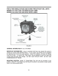
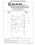
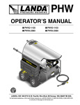
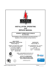
BECKETT CLEANCUT INSTALLATION INFORMATION
SINGLE STAGE FUEL UNIT
Part No. 21844
GENERATION INFORMATION - ALL SYSTEMS
IMPORTANT INFORMATION Long or oversized inlet lines may
require the pump to operate dry during initial bleeding period. In
such cases, the priming may be assisted by injecting fuel oil in
the pump gearset. Under lift conditions, lines and fittings must be
air tight. To assure this, oil-resistant pipe joint compound may be
applied to both the used and unused inlet and both return fittings.
WARNING
!
Please read and understand the manual supplied with this equipment. This equipment must be installed, adjusted and put into
operation only by a qualified individual or service agency that is:
y Licensed or certified to install and provide technical service
to oil heating systems.
y Experienced with all applicable codes, standards and ordinances.
y Responsible for the correct installation and commission of
this equipment.
y Skilled in the adjustment of oil burners using combustion
test instruments.
The installation must strictly comply with all applicable codes,
authorities having jurisdiction and the latest revision of the National Fire Protection Association Standard for the installation of
Oil-burning Equipment, NFPA 31 (or CSA-B139 and CSA-B140
in Canada).
Regulation by these authorities take precedence over the general
instructions provided in this installation manual.
!
WARNING Oil Leak & Fire Hazard
y
The inlet and return line pressures must not exceed 3 psig,
or pump seal damage and oil leaks could result! See NFPA
31-25, 8.6.3.
Do not use a check valve in the inlet line of a 1-pipe system
(with or w/o a boost pump), or in the return line of a 2-pipe
system.
NFPA 31-25, 8.5 states that ‘A return line from a burner or
pump to a supply line shall have no valves or obstructions
and shall enter the top of the same tank.’
Check valve flow restriction in a return line can elevate
pressures and damage the fuel unit seals.
Dangerous thermal expansion of oil trapped by an inlet
line check valve can create extreme pressures that damage
fuel unit seals, line fittings, inlet filters, gauges and other
components. A properly installed vacuum safety valve, such
as Suntec PRV-38, having accumulator effect and pressure
relief to tank is acceptable in the inlet line.
Do not use teflon tape or compression fittings.
y
y
y
y
CAUTION
This pump must be used with
a controlling device that provides a valve on delay (pre-purge).
!
Professional Service Required
Incorrect installation, adjustment, or misuse of this burner could result in severe
personal injury, death, or substantial property damage from fire, carbon monoxide
poisoning, soot or explosion.
y
2-STAGE
2STAGE FUEL UNIT
Part No. 21941
Beckett
INLET
USE ONLY WITH
VALVE ON DELAY
A2EA-6520
4 GPH 100-150 PSI 3450 RPM
NO. 2 & LIGHTER FUEL
3 GPH 150-200 PSI 3450 RPM
NO. 2 FUEL
INLET
BY-PASS
Made by Suntec
Exclusively for Beckett
Figure
11
FIGURE
MOUNTING POSITION Beckett CleanCut fuel unit may be
mounted in any position (except upside-down during single pipe
installation).
VACUUM CHECK A Vacuum Gauge may be installed in either
of the 1/4” NPT inlet ports. The Beckett CleanCut pump should
be used where the vacuum does not exceed 6” hg. single pipe
and 12” hg. two pipe. The Beckett CleanCut XL pump should be
used where the vacuum is less than 17” hg. Remember, running
vacuum is the total of all pressure drops (eP) in the system from
tank to inlet of pump.
PRESSURE CHECK When a pressure check is made use either
the BLEED PORT OR NOZZLE PORT.
CUTOFF CHECK To check cutoff pressure, dead head a pressure gauge in nozzle port. Run burner for short period of time.
Shut burner off. The pressure will drop and hold above zero.
MOUNTING PUMP (If the shutter screw interferes
with the solenoid on the fuel unit)
To install a CleanCut fuel unit on chassis with existing shutter tab
see Figure 2 and follow these steps:
Remove existing fuel unit and solenoid valves, if applicable, and
appropriately dispose of them.
Note the air setting of the shutter, then remove the air shutter, set
the shutter aside to be reinstalled.
DO NOT INSTALL
THE TOP SHUTTER
SCREW IF IT INTERFERES WITH THE
SOLENOID ON THE
FUEL UNIT.
OO
LOWER SHUTTER SCREW
R.W. BECKETT CORPORATION
U.S.A.: P.O. Box 1289 · Elyria, Ohio 44036
Canada: R.W. Beckett Canada, Ltd. · Unit #3, 430 Laird Road · Guelph,
Ontario N1G 3X7
Form Number 61583 R07
© 2007 R.W. Beckett Corporation 10/07
SHUTTER TAB
(REMOVE)
Figure 2
Remove the shutter tab by using a pair of side cutter pliers and
file sharp edges flush with burner surface. This will permit the
shutter to be locked securely.
Install the air shutter using the screw located below the pump.
Adjust the shutter to the original air setting and tighten screw
securely.
NOTICE On older burners, do not install the top shutter
‘H’
screw, it will interfere with the solenoid on the fuel unit.
To install a CleanCut fuel unit on a housing that has two top shutter mounting screw holes, make sure the screw is installed in the
hole on the left that is closest to the front of the burner (air tube
side).
Other Mounting Installations: The CleanCut Pump with a
standard cord set or a PD Timer can be installed on the following
burners: Carlin EZ-1, Wayne ’M’, Wayne ’E’, Wayne ’HS’, Ducane
’DM’, or Aero.
Ducane ’DR’: 5/16” diameter hole will have to be drilled into the
housing through the wire cavity.
Weil ’QB’: The valve coil blocks the air shutter screw. Allow
enough slack in the cord set in order to pivot the valve coil away
from the housing.
Figure 4
‘R’
Lift - ‘H’ in
Figure 4
(ft)
Run - ‘R’ in Figure 4
Single Stage Pump
(4GPH)
SYSTEM INSTALLATION REQUIREMENTS
ONE-PIPE SYSTEM
!
DO NOT Install bypass plug - the shaft seal will rupture!
Connect inlet line to pump inlet. Start burner. Arrange primary
burner control for continuous operation during purging. Open
bleed valve 1 turn CCW. Bleed unit until all air bubbles disappear. Notice: Hurried bleeding will impair efficient operation of
unit. Tighten bleed valve securely.
The Clean Cut fuel unit may be installed with a Gravity or Lift Oil
Supply System. The maximum allowable lift is 8 ft.
IMPORTANT: One pipe installations must be absolutely air tight
or leaks or loss of prime may result. Bleed line and fuel unit
completely. Bleed for 15 seconds after last air is seen from bleed
/ gauge port to be certain lines are air free.
L = line Length in Feet H = Head in Feet Q = Firing rate in GPH
3/8” Line
L=
*6-.75H
.0086Q
1/2” Line
L=
*6-.75H
.00218 Q
SK9859
Run - ‘R’ in Figure 4
Two-Stage XL Pump
(4GPH)
3/8” OD
tubing
1/2” OD
tubing
3/8” OD
tubing
1/2” OD
tubing
0
84’
100’
93’
100’
2
73’
100’
85’
100’
4
63’
100’
77’
100’
6
52’
100’
69’
100’
8
42’
100’
60’
100’
10
31’
100’
52’
100’
12
21’
83’
44’
100’
14
-
41’
36’
100’
16
-
-
27’
100’
18
-
-
-
76’
WIRING INSTRUCTIONS
SOLENOID WIRING
!
Disconnect power supply before wiring to prevent electrical shock or equipment damage.
Lead wires on these devices are long enough to reach the junction box on most burner installations. Note: check the burner
manufacturer’s installation sheets for correct solenoid wiring.
(See Figure 5). All electrical work must be done according to local and national codes. (Solenoid 115V, 0.1 amp, 60 HZ)
* If tank is above pump, change – to +. Fittings, valves and filters
will reduce total length allowed.
VIOLET
WHITE
MAXIMUM 1 PIPE (H)
LIFT: 8FT
Figure 3
SK9858
TWO-PIPE SYSTEM
Remove 1/16” pipe bypass plug from plastic bag attached to unit.
Remove 1/4” plug from return port. Insert by-pass plug. Attach
return and inlet lines. Start burner – Air bleeding is automatic.
Opening air bleed valve will allow a faster bleed if desired. Return line must terminate 3-4” above supply line inlet. Failure to
do this may introduce air into the system and could result in the
loss of prime.
Figure 5
REPLACEMENT PARTS
Item
Beckett Part Number
Strainer/Gasket
51974U
Valve stem
21877U
Valve Coil (115vAC)
21755U
Valve Coil (220/240vAC)
21756U
Valve Coil (12vDC/24vAC)
21754U
PD Timer
21887U
Valve Cord Set
21807