1
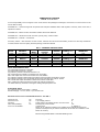
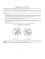
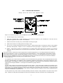
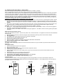
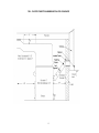
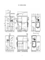
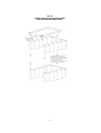
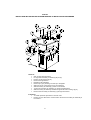
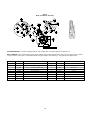
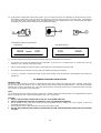
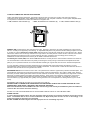
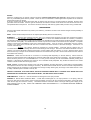
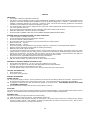
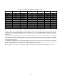
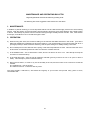
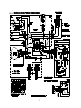
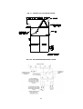
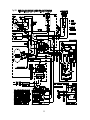
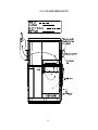
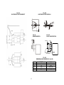
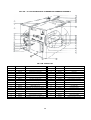
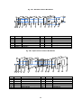
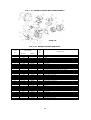
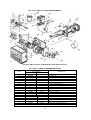
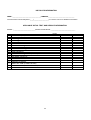
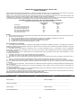
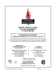
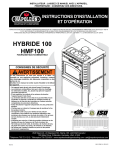
INSTALLATION, OPERATING and SERVICE MANUAL NEWMAC COMBINATION FURNACE CLC 90-100 E The installation of the unit shall be in accordance with the regulations of the authorities having jurisdiction. HEAD OFFICE MARKETING / PRODUCTION Newmac Mfg. Inc. DEBERT AIR INDUSTRIAL PARK, 208 LANCASTER CRESCENT P.O. BOX 9, DEBERT NOVA SCOTIA, BOM 1G0 PHONE: 902-662-3840 FAX: 902-662-2581 WAREHOUSE Newmac Mfg. Inc. 430 SPRINGBANK AVE., SOUTH WOODSTOCK, ONTARIO N4V 1B2 PHONE: 519-539-6147 FAX: 519-539-0048 EMAIL: [email protected] HOMEPAGE: newmacfurnaces.com CSA B415.1 156156 NOTICE TO HOMEOWNER: READ THESE INSTRUCTIONS SAVE THESE INSTRUCTIONS 2210039 April 2012 Subject to change without notice Printed:__________ COMBINATION FURNACE MODEL CLC 90-100 E It is the responsibility of the consignee of the unit to examine the packages for damages, and if found, to note the same on the Carrier’ Bill of Lading. PACKAGE # 1 – Heat exchanger with end panels and side panel installed, filters, draft regulator, accessory carton, brick rack, 8 split brick in firebox. PACKAGE # 2 – Blower section with blower installed, blower belt attached. PACKAGE # 3 – Oil Burner box with oil burner, primary relay, cell and nozzle. PACKAGE # 4 – Firebrick – 20 full brick Accessory Carton – Wire harness, fan limit control, solid fuel and oil burner thermostats, junction box with relay transformer mounted, blower motor and pulley, draft fan package, Instruction Manual. FIG. 1 - GENERAL INSTRUCTIONS MODEL BECKETT BTUH INPUT BTUH OUTPUT NOZZLE PUMP (p.s.i.) INSERTION CLC90E CLC100E AFG (NM502) AFG (NM502) 105,000 119,000 89,000 98,000 .75 (70 A) .85 (70 A) 100 100 7-7/8” 7-7/8” MODEL RIELLO BTUH INPUT BTUH OUTPUT NOZZLE PUMP (p.s.i.) INSERTION CLC90E CLC90E CLC100E 40 F3 (10” BT) 40 F3 (10” BT) 40 F3 (10” BT) 111,000 111,000 119,000 95,000 95,000 102,000 0.65 (60W) 0.65 (60AB) 0.75 (60W) 150 150 130 7-1/2” 7-1/2” 7-1/2” WOOD PERFORMANCE DATA Avg. particulate emissions: 0.035 g/MJ Avg. particulate emissions: 1.69 g/hr Avg. efficiency based on delivered heat: 83.17 % Min. heat output from CSA B 415 emission test: 34,544 Btu Max. heat output from CSA B 415 emission test: 108,368 Btu Avg. efficiency based on HHV (High Heat Value) of fuel and stack loss method: 72.95% Avg. efficiency based on LHV (Low Heat Value) of fuel and stack loss method: 78.56% Min. overall heat output rate based on stack loss method: 27,985 BTU Max. overall heat output rate based on stack loss method:103,507 BTU The stated efficiency is based on the higher heating value(HHV)of the fuel ELECTRICAL DATA Avg. electrical power consumption: 0.183 kw Electrical Supply: 115 vac, 60 HZ, 1 ph, less than 12A Minimum Clearance From Combustible Surfaces: See FIG. 6 Oil burner end Wood door end One side Other side (walkway) Floor non-combustible 24" 48" 6" 24" Flue Pipe 18” Top of Supply Plenum 6” Supply Plenum and takeoff ducts to 6' from furnace 6” Duct beyond 6' from furnace 1/2" In USA next 3’ 3", balance 1" Return Air is “otherwise certified” to be installed as per CSA B139 Clearances (Unlined Joist Space may be used for the Return Air as there is no radiation in the Return Air section) Effective August 2008 Refer to Canadian Building Code 1 COMBINATION FURNACE INSTALLATION Check with provincial, state or local codes concerning clearances, chimney requirements and other installation procedures before installation. Some codes may vary from the requirements set forth in this manual. To ensure the furnace is on a level foundation and above any possible dampness, a cement pad is recommended. It is important that the top be level. Install as close to the chimney as possible so that a minimum of pipes and elbows may be used. If unit is installed in an enclosed area (furnace room), ventilation must be provided for the burner – minimum of one square inch for every 1,000 BTU. 1. The NEWMAC COMBINATION FURNACE may be installed with the supply or return air on either side. The units leave the factory with the return or cold air on the right when viewed looking at the oil burner end. If it simplifies the duct installation to have the supply air on the opposite side, remove the installed panel and install it on the other side. 2. After placing the heat exchanger on the proper side of the pad, assemble the blower section to the heat exchanger section by lining up the prepunched holes and metal screwing together. 3. Install the oil nozzle in the burner firing assembly, and check to make sure adjustments are according to Fig. 14. Install the oil burner by mounting it on the burner mounting plate. Check to make sure the oil burner tube is aligned with the hole in the combustion chamber. 4. Install junction box, fan/limit control, draft fan and thermostat as in Fig. 7. Note recommended setting. FIG. 2 - THERMOSTAT HEAT ANTICIPATORS HONEYWELL T822 WHITE ROGERS IF30 In order to prevent short cycling, the heat anticipator in the thermostats must be set at .4 amps as indicated in the diagrams below. WARNING: The heat anticipator will BURN OUT IF 25 volts are applied directly to thermostat by shorting out primary control during testing or incorrect wiring. If this happens the warranty on the thermostat is void. 2 FIG. 3 - FAN AND LIMIT CONTROLS Settings: Fan off – 95 F, Fan on – 130 F. High limit – 180 F NOTE: For constant fan operation, push the MANUAL-AUTO switch on button to MAN position. 5. Connect wiring as in Fig. 10 (All models). 6. Install the oil storage tank or tanks according to the instructions supplied by the manufacturer of the tank and the appropriate regulation for the location of the installation. 7. Install brick in firebox according to Fig. 8A and baffles according to Fig.8B. 8. Install motor and belt on circulating blower according to Fig.9. 9. Do not use a manual flue pipe damper with this furnace. Optimal draft should be controlled by means of the supplied barometric draft regulator – adjust to a -.03 to –0.5 draft at the chimney (see page 11, paragraph 5 for correct installation). 10. Caution: If this furnace is used as a replacement for an existing furnace make sure there is a minimum of 6” clearance above the warm air plenum as far as 6 feet out from the furnace. Beyond 6 feet there must be a minimum of 1/2” clearance. This furnace must be connected to a chimney approved for wood burning appliances, ie. ULC S629 (Canada) and UL103 (US). Newmac recommends an 7” round or 7” square chimney flue (inside dimension). It is the responsibility of the installer to ensure there is sufficient draft in all cases. Draft should be between -0.03 and -0.05 ins wc. No other appliance should be connected to this chimney flue for installations in the US. No other appliance should be connected to this chimney flue unless the installation conforms to clause 5 of B365 and providing there is sufficient draft, in Canada. amended April 2011 The installation must conform with the regulations of the local authorities having jurisdiction with the applicable Electrical Code, and C.S.A. Standard B139 “The Installation Code for Oil Burning Appliances and Equipment” and with the regulations in C.S.A. Standard B365 “The Installation Code for Solid Fuel Burning Appliances and Equipment” when pertaining to supply air plenum clearances and flue pipe installation. The flue pipe must be black 24 ga pipe minimum. Caution: The flue collar is sized so that a trade size flue pipe fits snugly inside it. Joints in flue pipes, including the connection at the appliance and the chimney, shall have at least 30mm (1 3/16”) overlap. Flue pipe connections must be secured with at least 3 metal screws or an equivalent mechanical means; and be made tight in accordance with good practice. The flue pipe shall have joints arranged so that condensation from the chimney will drain towards the appliance, and not have longitudinal seams located on the underside, in horizontal runs. The flue products may contain carbon monoxide particularly when the wood fire is being starved for air (made to burn at slow rate). Therefore, the flue pipe must seal tight and must not be inserted into the return air stream of the circulating blower. 3 Wood storage should conform to local bylaws, and should not be within the appliances minimum clearances for combustible surfaces as shown on Page 1. Do not store fuel within the space required for fuelling, ash removal, and other routine maintenance operations. This furnace must be installed by a qualified furnace service person. COMBUSTION AIR: Where fans are used in the fuel storage area, they should be installed so as not to create negative pressure in the room where the solid fuel burning appliance is located. OUTSIDE COMBUSTION AIR: Provision for outside combustion air may be necessary to ensure that fuel-burning appliances do not discharge products of combustion into the house. Guidelines to determine the need for additional combustion air may not be adequate for every situation. If in doubt, it is advisable to provide additional air. Outside combustion air may be required if: 1. the solid-fuel-fired appliance does not draw steadily, experiences smoke roll-out, burns poorly, or back-drafts whether or not there is combustion present; 2. existing fuel-fired equipment in the house, such as fireplaces or other heating appliances, smell, do not operate properly, suffer smoke roll-out when operated, or back-draft whether or not there is combustion present; 3. any of the above symptoms are alleviated by opening a window slightly on a calm (windless) day; 4. the house is equipped with a well-sealed vapor barrier and tight fitting windows and/or has any powered devices which exhaust house air; 5. there is excessive condensation on windows in the winter; or 6. a ventilation system is installed in the house. If these or other indications that infiltration air is inadequate, additional combustion air should be provided from the outdoors. DUCT INSTALLATION: The plenums and warm air supply ducts must be constructed of metal. To prevent excessive noise 2 and temperature rise, limit the minimum return air duct size to at least 250 square inches (in ). Because the unit may be used as a gravity furnace when the power is off, the following is recommended: 1. Locate the furnace as centrally as possible in the home so the best warm air distribution may be enjoyed. 2. Use an extended plenum (central duct) at least one size larger than called for in National Warm Air Standards. 3. Use a minimum pipe size of six inches in diameter in runs and in no case smaller than five inch diameter. 4. Slope extended plenums and runs as much as possible to facilitate gravity flow of warm air. IMPORTANT: Model CLC90-100E FIG. 4 - MINIMUM DUCT SIZES Return Air 250 sq. in. Supply Air 180 sq. in. Static Pressure .20” W.C. The above chart gives the MINIMUM free area duct size. The supply air extended plenum should be 8 – 10 feet out from the furnace with the sizes shown in the chart, then gradually transitioned to the end of duct system. If the plenum is lower than 24 inches high, increase the duct size proportionately. HUMIDIFIER: Install humidifier in the return air plenum. This prevents possible damage due to excessive temperatures when there is a power failure. Metal connecting ducting from the warm air plenum should be used. 4 OIL FIRED BLOCKED VENT SWITCH - MODEL WMO-1 Refer to the Newmac and Field Controls Instructions enclosed in the WMO-1 package. Do not use the WMO-1 Blocked Vent Switch with the Newmac SVS Sealed Vent System When installed on the chimney vent or on the appliance burner plate according to these instructions, the manually reset WMO1 blocked vent switch is designed to shut off power to the oil burner if the hot flue gases in the chimney vent connector pipe back up sufficiently to activate it. The WMO-1 switch is required on new Newmac oil-fired and combination furnaces or boilers installed in Canada. It must be installed by a qualified installer in accordance with the manufacturer's installation instructions. Electrical wiring must be in accordance with applicable codes and the Canadian Electrical Code. Before leaving the appliance check that the WMO-1 switch and its cover are tightly secured. Installation on the Burner Plate - combinations - Figs. 5A and 5B 1. See Fig. 5A. Remove the 5/8" diameter plug in the burner plate. Cut or file a hole in the rigid fibreglass insulation, behind the 5/8" hole in the burner plate, large enough that the WMO-1 securing nut will seat against the back of the burner plate. Remove one of the securing nuts from the tube of the WMO-1 assembly. Tighten the remaining nut onto the tube as far as possible. 2. See Fig 5B. With the WMO-1 assembly outside the burner plate, insert the threaded tube end into the 5/8" diameter hole in the burner plate, re-install the first securing nut onto the tube on the inside of the burner plate. Tighten securely. CAUTION: Disconnect the electrical power supply before wiring the WMO-1 assembly. 3. See Fig. 5C. Using suitable AC90 flexible (BX) conduit or equivalent, wire the WMO-1 switch in series with the appliance limit circuit. Connect at the burner junction box. 4. Check the operation of the WMO-1 switch before leaving the appliance. The WMO-1 switch is reset by pushing the square red button. WMO-1 Blocked Vent Switch Check Note: take appropriate precautions - this test can produce soot, smoke and fumes. The appliance should not be left unattended during the test. 1. With the appliance shut down, block the vent pipe at the downstream (chimney) side of the barometric damper. 2. Start the appliance. 3. The WMO-1 switch should stop the oil burner in less than 10 minutes. 4. After the test, turn off the appliance and let it cool. 5. Remove the blockage from the vent pipe. 6. Reset the WMO-1 switch by pushing in the square red button until it clicks. 7. Ensure that the appliance is in a safe condition. Maintenance and Cleaning The WMO-1 switch assembly should be checked and cleaned at least once a year and after any time the switch has shut off the burner. Cleaning procedure 1. 2. 3. 4. 5. 6. 7. Switch off the electrical power to the appliance. Remove the WMO-1 cover. Remove the two mounting screws for the thermodisc temperature sensor. Carefully pull the sensor to one side. Using a suitable soft brush or cloth carefully clean any soot from the surface of the sensor and the inside of the 5/8" diameter tube. Replace the sensor and secure with its mounting screws. Check that the wiring is in good condition and secure. 8. Check that the 5/8" diameter tube and its securing nuts are tight. 9. Replace the cover and tighten the mounting screws. 9. Check the operation of the WMO-1 switch as described above. Troubleshooting If for any reason the WMO-1 switch shuts the appliance down during operation, the cause of the shut down should be investigated and corrected before resetting the switch and restarting the appliance. The blockage switch is reset by pushing the square red button until it clicks. FIG. 5A Securing Nut FIG. 5B FIG. 5C View Port WMO-1 Viewport Primary Control T T F F Limit 5/8" hole WMO-1 Securing Nuts WMO-1 Tube Horizontal N Cad Cell Connect WMO-1 at appliance junction box (except CL series) Burner Plate Burner Burner Plate Motor CL series combination furnaces: Connect WMO-1 at the burner control junction box Ignition 5 Burner FIG. 6 - FLUE PIPE CONNECTION & MINIMUM INSTALLATION CLEARANCES 6 FIG. 7 - CONTROL LOCATIONS 7 FIG. 8A FIREBOX INSTALLATION PROCEDURE WITH STAINLESS STEEL FRONT 8 FIG. 8B BAFFLE AND SECONDARY AIR SYSTEM REMOVAL & INSTALLATION PROCEDURE Removal: Gain access through firedoor Lift right side secondary air baffle (2) off pin (D) Ensure pin (D) clears hole (E) Remove through firedoor Repeat for left side baffle Remove pin (3) by bending one side up to straighten Slide pin (3) out of mounting hole (C) of bracket (F) Slide secondary air assembly (1) back out of bracket Tip front of secondary air assembly (1) down towards firedoor Slide secondary air assembly forward off right & left side mounting clip (A) Remove the secondary air assembly (1) through the firedoor Installation: To install repeat the procedure in reverse order Ensure pin (3) is bent down on both ends to secure the secondary air assembly in the furnace 9 FIG. 9 Motor and Blower Assembly MOUNTING MOTOR: If motor is equipped with oil caps, rotate motor in mounting base so oil caps are up BELT TENSION: When adjusting the proper pulley setting make certain that the belt is able to flex at least one inch without movement of the motor pulley. The belt should be just tight enough to avoid slippage. Align pulleys with straight edge. ITEM NO PART NO DESCRIPTION ITEM NO PART NO DESCRIPTION 1 2040105 G9 Twin Circulating Blower c/w 8” Pulley 10 2040141 Blower Motor Mounting Bracket 2 2240003 8” x ¾” Blower Pulley 11 2120027 5/16” x ¾” Sq. Head Screw 3 2240001 3 ¼” x ½” Variable Speed Motor Pulley 12 2150001 5/16” Washer 4 2240040 40” x ½” Belt 13 2130002 5/16” Nut 5 2130010 Motor Adjustment 14 2130002 5/16” Nut 6 2140002 ¾” x ¼” Hex Cap Screw (2) 15 2130010 Motor Adjustment 7 Motor Frame 16 2130011 Motor Adj. Leg Rubber Foot 8 2150004 ¼ Washer 17 2020002 1/3 HP Belt Drive Blower Motor 9 2130003 ¼” Hex Nut 10 COMBINATION OPERATING INSTRUCTIONS 1. When the installation is complete set both burner and solid fuel thermostats to the bottom of the scale. 2. Close the supply switch and turn the solid fuel thermostat above room temperature. The draft fan should operate. If this fails to happen, check (a) power supply, (b) voltage on secondary side of control relay – transformer, (c) correct wiring hook up, (d) correct voltage at fan motor. If (a) to (d) check OK, the fan is defective. 3. Open the line switch, turn the solid fuel thermostat to its lowest setting and the oil burner thermostat above room temperature. Remove the air bleed plug from the pump (refer to Diagram attached to pump) (a) open oil supply valve, (b) place a container in position to catch foam, (c) close the line switch and after pure oil is emitted, open the line switch and replace bleed plug, (d) close the line switch and the oil burner should run normally after a few seconds. 4. Adjust oil burner air control so that a # 1 or less smoke is arrived at by means of a smoke test. Close all three slide plates when doing the smoke test – see paragraph 10 of this section. If a smoke tester is not available, slowly close the air adjustment until the fire becomes smokey. Slowly open the air adjustment until there is a small amount of smoke on the flame tips. 5. By means of the barometric draft regulator – adjust to a - .03 draft at the chimney. This must be done by means of a draft meter. The maximum draft is not to be more than - .05 as damage can result to the furnace when used as a gravity unit. The test must be made between the flue collar on the furnace and the draft regulator. A flue gas analysis should be made with all three slide plates closed (see paragraph 10 of this section) and the unit adjusted so that between a 8 % and 10 % 2 CO is registered. 6. The combination fan & limit switch is thermally operated. The limit side is connected in series to the power supply to the oil burner. Because of blower failure, dirty filters or some other cause, the present limit will interrupt the power supply to the burner. If the limit switch shuts the unit down it may be because of a common fault, not enough return air supply or a supply air grill being covered by a rug. The load side of a limit also supplies power to the transformer – relay. If the unit goes off on limit, the draft fan will shut off. 7. The fan side of the combination control is adjustable with fan on and off fingers. If the furnace fan has been adjusted to o o odeliver a 75 F temperature rise (difference between return air and supply air) a setting of fan on 130 F and off at 90 100 o F is comfortable. The temperature rise in accomplished by speeding up or slowing down the fan by means of the o adjustable pulley on the fan motor. Maximum temperature rise is 75 F on CLC 90-100 E. o The motor pulley is factory set but should be adjusted to give a 75 F temperature rise at a .20” W.C. or .25”W.C. static pressure (air resistance in duct work). Since most home duct work does not have resistance of the value the fan speed must be adjusted by means of the following: With the oil burner operating, place a thermometer in the warm air supply (place thermometer so that it cannot see the heat exchanger) and measure the temperature after the unit has been operating for at least 5 minutes. (Be sure the blower door o is closed) measure the return air (at return air grill). If the difference is less than 75 F slow the fan speed by opening the o motor pulley or if it is greater than 75 F close the pulley. In the majority of cases the fan must be slowed. By means of the motor adjustment bracket, adjust the motor so that the belt may be deflected approximately one inch. This adjustment is important as a tight belt causes excessive fan bearing wear, it uses more electricity and it is noisy. If the above instructions are followed, continuous air circulation can be comfortably accomplished without the added expense of a two speed motor, simply by using the manual fan switch on the face of the combination control. 8. Before loading the solid fuel firebox, turn the thermostat up to insure that the draft fan is on: after the fire is established set thermostat to desired temperature. IMPORTANT: Learn how to load your solid fuel box with wood so as to maintain a comfortable home temperature. The amount of fuel required depends upon your home’s heating requirements. A small and intense fire is preferable to a large smoldering one to reduce the amount of creosote deposition. 9. The oil burner thermostat on combination furnaces is generally set about 5 F to 10 F (3 C to 5 C) lower than the solid fuel side. When the solid fuel thermostat is calling for heat, the draft fan is on. If the fuel has been depleted and cannot keep the temperature up, the oil burner thermostat brings the oil burner on. The NEWMAC COMBINATION FURNACE has a relay that stops the draft fan when the oil burner comes on, making the oil fuel side efficient, and making the furnace operate safely. 0 11 0 0 0 10. (a) By means of slide plate A above the firedoor, you can control the amount of combustion air allowed into the fire box. The position of slide plate A will vary with heat requirement, as well as size and type of wood being burnt. Slide plates B and C should be open when burning wood. For added efficiency, when heating with oil only, close all three slide plates and adjust your solid fuel thermostat to its lowest temperature setting. (b) FURNACE LABEL ILLUSTRATION Draft Slide A Draft Slides B and C DRAFT CONTROL SOLID FUEL MAXIMUM MINIMUM DRAFT CONTROL OIL ONLY OIL ONLY SOLID FUEL CLOSED CLOSED MAXIMUM 11. For safe operating procedures for solid fuel burning, refer to the notice label on the furnace. The furnace room must have adequate air for combustion. If the unit is in a confined space, on square inch of free air access for every 1,000 BTU must be provided. Use a chimney suitable for solid fuel, which must be kept free of accumulations of soot and ash. Accumulations of soot and ash not only create a fire hazard but cause poor efficiency. In case of a soot fire, move all thermostats to their lowest setting, close the barometric draft regulator and call the fire department. OIL BURNER OPERATING INSTRUCTIONS GENERAL CARE This burner is fully automatic in operation. All adjustments have been carefully set and should not be changed. Keep burner free from excess dirt and moisture. Any oil leaks, however small, should receive immediate attention. The oil filters should be cleaned once a year by the service man. The motor should be given a few drops of light oil two or three times a year if oil cups are provided. No other parts require lubrication. FUEL The supply tank should be kept at least one quarter full. Outside underground storage tanks if not equipped with a special gauge, are gauged by stick. Recommended grade of fuel: No. 2 Furnace Oil. CAUTION 1. DO NOT USE GASOLINE CRANKCASE OR ANY OIL CONTAINING GASOLINE. 2. DO NOT TAMPER WITH THE UNIT OR CONTROLS, CALL THE SERVICE TECHNICIAN. 3. Do not attempt to start burner when excess oil has accumulated, when the heating unit is full of vapour, or when the combustion chamber is very hot. 4. Do not start the burner unless the blower access door is secured in place. 5. DO NOT BURN GARBAGE OR PAPER IN THE HEATING SYSTEM, AND NEVER LEAVE PAPER OR RAGS AROUND THE UNIT. 12 HEATING PLANT Give your Heating unit the proper care and attention. The use of the furnace as an incinerator is not recommended. Heating unit flues should be kept clean for economical operation. Dampers are set by installation technicians and should not be changed. Free ventilation must be permanently provided in the room where the burner installation is made. CONTROLS The operation of the burner is normally controlled by room thermostat, which may be set for any temperature desired, usually 0 70 F. If a higher or lower temperature is desired, the indicator should be moved to the proper point on the scale. To shut down burner at any time, turn main switch to off position. SUMMER SHUT DOWN When burner is not to be used during the summer months turn off burner main switch. If the heating unit room is damp, protect burner against dirt and moisture with light cover. SAFETY SHUT-OFF An emergency oil shut-off valve should be installed as required by local ordinance. Always keep the valve shut-off if the burner is shut down for an extended period of time. SERVICE: If burner fails to run when the thermostat or other operating control is calling for heat see that the main switch is turned on and that fuses are not blown. Be sure there is oil in the supply tank and that the electric service to the building has not been temporarily interrupted. Press button on burner control box and if burner still fails to start call the service person. A periodic inspection of the burner is recommended. BURNING WOOD OPERATING INSTRUCTIONS When installation is complete, turn on the power switch and turn the thermostat above room temperature. Check to make sure the forced draft fan above the fire door is operating when the thermostat is set above room temperature. The draft fan should be off when thermostat is set below room temperature. The maximum draft is not to be more than - .05 as damage may result to the furnace when operated as a gravity unit. The motor pulley is factory set but should be adjusted to give an adequate temperature rise under most conditions. However, because of various temperatures that can result from burning wood, the blower speed can be adjusted by the motor pulley. The temperature rise is the difference in temperature between the hot air plenum and the cold air plenum and under no o o circumstances should the temperature rise be more than 80 F (27 F). NOTE: Before loading the fire box, turn the thermostat up to insure that the draft fan is on. This provides an air curtain to avoid smoke roll out during loading and fans the coals to assist the ignition process of your new fuel. It also helps to promote draft when there is inadequate draft. After the fire is established, set the thermostat to desired temperature. To start the fire, turn up the thermostat to Maximum setting to turn ON Forced Draft Fan. Place some newspaper crumpled up in the bottom of the firebox on top of the minimum requirement of 2” of sand , ash or firebrick. Add some small kindling and light the fire. When the fire starts add some larger pieces of kindling or wood until you have a good fire. The idea is to ultimately end up with a good bed of ash and coals which helps to maintain a good controllable fire. When reloading the firebox there will be a build up of ash and coals from the previous fire. Rake the coals mixed with ash to the front of the firebox which places the coals at the front. Load in your wood and the fire should light in a few minutes. When the firebox gets full of ash (within two inches of door level), some morning, before loading the firebox, push or rake the coals to the rear of the firebox. Remove the ash from the front of the firebox using the shovel supplied for this purpose. Refer to Maintenance section on Page 15 for proper removal of ash instructions. When the ashes only are removed from the front, rake the coals from the back to the front. Load in desired amount of wood and the fire will again be burning in a few minutes. The fire burns best when the ashes and coals are 3” to 4” below the fire door level. Return wood thermostat in main living space to desired setting. For safe operating procedure, refer to the “Notice” label on the furnace. 13 TYPES OF COMBUSTION AIR FOR WOOD HEATING Unlike older airtight heating appliances, low emission furnaces have more than one location and control for supplying combustion air into the firebox. These additional air inlets allow for near complete combustion of wood gases and particulates. It is important to understand how these three different air supplies work. 1. PAC, PRIMARY AIR CONTROL (A) 2. SAC, SECONDARY AIR CONTROL (B) 3. LPA, LOWER PRIMARY AIR (C) PRIMARY AIR (A) starts the fire and controls the burn rate. Opening or closing this air supply regulates how hot the furnace will burn. Primary air is supplied by the following: an adjustable slide plate to vary the burn rate and sliding the plate to the Left is a hotter fire. Use the Primary Air Control (PAC) slide plate knob on the left side of draft fan to control the burn rate. Always start the fire with the PAC set on high and leave it on high until the secondary flames continue to burn at the rear of the firebox below the baffle, then adjust the PAC to a lower setting (to the right). Adjust the PAC accordingly when refueling. An established hot coal bed requires less Primary Air to restart a fresh load of firewood. The Primary Air Control (PAC) also called COMBUSTION AIR is normally set in the center between maximum and minimum. The Thermostat also controls the amount of primary air entering the unit by turning on the draft fan and adjustment of slide plate (A). Turn up the thermostat for 10 to 20 minutes after reloading for a good start, then turn down to desired temperature. It is very important to keep the secondary flames burning to maximize heat output and minimize air pollution, so some experimentation will be necessary because each installation is different. Wood moisture content will also affect the amount of time that a unit will need to burn on high after each reload. SECONDARY AIR allows the furnace to burn clean. This preheated air enters the upper firebox just below the baffle plate. This superheated air mixed with the wood gases and flames ignites, reaching temperatures in the 1100F to 1600F range. Without Secondary Air these volatile gases would exit the furnace unburned as creosote, smoke, particulates, and high levels of Carbon Monoxide, increasing pollution and greatly decreasing efficiency. Heat comes from burning the wood gases, not the wood, which itself turns into black charcoal after the gases are all released and then to grey ashes. Secondary air increases a furnaces efficiency by approximately 40% greatly reducing the amount of wood required for a heating season (up to 1/3 less wood). SECONDARY AIR SLIDE (B) is located on the right side of the draft fan. NEVER ATTEMPT TO BURN YOUR FURNACE WITH THE SECONDARY SLIDE IN THE CLOSED POSITION AS YOUR FURNACE WILL BURN POORLY AND DIRTY AND PRODUCE CREOSOTE. SAC & LPA Slide Plates must be OPEN at all times when burning wood and may be CLOSED only when the Oil Burner is fired as this will increase oil burner efficiency. DO NOT LET THE COALS/ASHES BUILD UP ANY HIGHER THAN HALF WAY UP THE FIRE BOX LINER. POWER FAILURE In case of prolonged power failure, first turn off power supply to furnace, then remove the blower access door and air filters. The draft fan will be off, to control combustion air, adjust slide plates for more or less air accordingly. Turn power switch back on after filters are reinstalled. DO NOT CHARGE the firebox higher than half way up the liner as overheating may result. 14 SAFETY Whenever a loading door is opened, it always should be cracked slightly before fully opening to allow oxygen to enter and burn any combustible gases that are present. Failure to do this could result in sudden ignition and explosion of the unburned gases when the door is opened. A furnace should never be filled with excess fuel so that the flue gas exit is in anyway blocked or impeded. Burning wood generates carbon monoxide. If the flue gas exit is blocked, the carbon monoxide can be forced out of the furnace into the room with possible fatal consequences. The furnace should be used only with chimney systems that provide a strong, reliable draft. MAINTENANCE Failure to follow these instructions may result in poor efficiency, excessive corrosion of the heat exchanger and the possibility of a creosote fire. DAILY: Check ash level daily and remove as required (see Monthly section for instructions). BI-WEEKLY: Furnace heat exchanger and flue pipe: The complete heat exchanger and flue pipe should be thoroughly inspected for creosote deposits, ash buildup, etc. (See pages 17 & 18 for more detailed information on creosote). Creosote or ash deposits must be removed by scraping and/or brushing the deposits from the heat exchanger surfaces (the baffle may have to be removed, see Fig.8B). An industrial vacuum cleaner may be used to assist in the removal of such deposits. A complete cleaning must be done immediately at the end of each heating season. If this is not done, condensation from the summer months, or any other source, will mix with the ash or creosote and cause corrosion of the heat exchanger. Corrosion is not covered under warranty. Chimney: The chimney should be inspected for creosote buildup. Chemical chimney cleaners are not recommended as they could damage the furnace heat exchanger and flue pipe. One of the most efficient methods to clean a chimney is to lower a stiff brush (chimney brush) tied to a heavy weight down the chimney on a rope. Work the brush up and down the chimney to scrape the accumulated creosote and soot off the chimney walls. Remove the residue from the cleanout at the base of the chimney. MONTHLY: Ashes must be removed on a minimum of a monthly basis depending on the ash build up. Ashes should be placed in a metal container with a tight-fitting lid, and other waste shall not be placed in this container. The closed container of ashes should be placed on a noncombustible floor or on the ground, well away from all combustible materials, pending final disposal. If the ashes are disposed of by burial in soil or otherwise locally dispersed, they should be retained in the closed container until all cinders have thoroughly cooled. NOTE: Establish a routine for the storage of fuel, care of the appliance, and firing techniques. Check daily for creosote buildup until experience shows how often cleaning is necessary. Be aware that the hotter the fire, the less creosote is deposited and weekly cleaning may be necessary in mild weather even though monthly cleaning may be enough in the coldest months. Have a clearly understood plan to handle a chimney fire. INSPECT FLUE PIPES, FLUE PIPE JOINTS, AND FLUE PIPE SEALS REGULARLY TO ENSURE THAT SMOKE AND FLUE GASES ARE NOT DRAWN INTO, AND CIRCULATED BY, THE AIR-CIRCULATION SYSTEM SEMI-ANNUALLY: Draft Fan – oil motor with #20 non-detergent oil if oil cups provided. ANNUALLY: Burner Motor and Blower Motor – oil with #20 non-detergent oil, if oil cups provided. In the spring, after the furnace is shut down for the summer, clean the heat exchanger of all soot, ash and creosote accumulation, remove all ashes, clean the flue pipe and clean the chimney. The baffles should be removed to allow a thorough cleaning and scraping of the heat exchanger (see Fig. 8B). KEEP THE FIREDOOR OPEN APPROXIMATELY 2” TO INSURE MOISTURE REMOVAL DURING SUMMER. 15 NOTICE IMPORTANT: This furnace is tested to CSA B366.1 and UL391 This furnace must be installed according to CSA Standard B365 “Installation Code for Solid Fuel Burning Appliances and Equipment” and CSA Standard B139 “Installation Code for Oil Burning Equipment” in Canada. This furnace must be installed to NFPA211”Standard for Chimneys, Fireplaces, Vents, and Solid Fuel Burning Appliances” and NFPA31 “Standard for the Installation of Oil Burning Equipment” in the US. The solid fuel side of this furnace is designed to burn wood only, unless equipped with grates thus allowing the burning of coal. Burn anthracite coal only. Proper flue draft must be maintained to allow combustion gases to flow freely out the chimney. ONLY ULC S629-650 C or masonry chimney is acceptable. IN USA DO NOT CONNECT THIS UNIT TO A CHIMNEY SERVING ANOTHER APPLIANCE. DANGER: RISK OF FIRE OR EXPLOSION, FOR SAFE OPERATION: Load fuel carefully or damage may result. Do not load solid fuel higher than the firebrick or cast liner. Do not use chemical or fluid fire starters. On combination units: Do not attempt to light a fire when there is oil vapour present. Minimum flue draft - - .03” W.C. Maximum flue draft - - .05”W.C. Do not burn garbage, manufactured fire logs, gasoline, naptha or crankcase oil or other inappropriate materials. Keep the furnace doors tightly closed except for refueling and cleaning. Maintain all door seals in good condition. To maintain furnace efficiency and prevent soot fires, clean the heat exchanger, flue pipes, and chimney at the end of each heating season to minimize corrosion during summer months and as frequently as required during the heating season to prevent soot accumulation. The furnace, flue and chimney must be in good condition. These instructions also apply to a draft inducer if used. Turn off power to the furnace when cleaning the furnace and flue. Do not store fuel or combustible material within the furnace clearances. Do not use salt wood (driftwood gathered from the seashore). WB, WG, & WFA models - the return air ducts are to be “metal” not “wooden”. WARNING: TO PREVENT DAMAGE AND RISK OF FIRE Do not set the flue draft above -- .05” W.C. as the fire could burn out of control. If equipped, do not open the furnace door slide plate damper during normal operation. Furnaces with grates must have ashes removed daily. Furnaces without grates require a minimum of 2” of sand or ash in the bottom of the fire box. CAUTION: HOT SURFACES Keep children away. Do not touch during operation. SPECIAL PROCEDURES POWER FAILURE: (1) Turn off power supply to furnace, remove the blower access door and air filters for better air circulation. If the furnace is in an enclosed area (furnace room) open the door to the room. Turn power switch back on after filters are reinstalled. (2) If equipped, to control the fire open the slide plate damper in the furnace door. THIS DAMPER SHOULD BE CLOSED FOR NORMAL OPERATION. (3) Do not load the fire box higher than half way up the firebrick or cast liner. SOOT FIRE Close all sources of air that can reach the fire through the furnace and draft regulator. Insure the draft fan above the fire door is turned off. Do not attempt to take the flue pipes down until the fire has been completely extinguished. RUNAWAY FIRE This can be caused by too high a flue draft or excessive fueling. (1) Close all sources of air to the furnace. Insure draft fan is turned off. (2) Set the barometric draft regulator wide open to reduce draft. The excessive heat caused by a runaway fire may damage the furnace safety controls. Their operation should be checked before the furnace is returned to service. After a soot or runaway fire inspect chimney connection and chimney. 16 PREPARATION OF WOOD Once I have my wood at home, how do I prepare it for burning? The wood must be cut to length to suit the firebox of the stove, furnace, or fireplace in which it is to be burned. An 8’ log may be cut into four, six or eight pieces, depending on the desired length. Splitting the wood greatly facilitates drying and reduces the wood to a more manageable size. How much moisture is contained in wood? Many softwoods have a moisture content in the vicinity of 55 percent when they are freshly cut. The popular hardwoods have moisture contents of about 45 percent. Air dried wood has a moisture content of about 15 percent and kiln dried wood may have a moisture content of less than 10 percent when it is fresh from the kiln. What causes wood to rot? When wood is cut, it is very susceptible to the growth of fungi, which converts the wood to water, carbon dioxide, and heat, just as does a fire. This rotting decreases the wood’s energy. The fungi are most productive when three conditions are met: the 0 0 temperature is between 60 F and 90 F, the wood’s moisture content is above 30 percent, and ample oxygen is available. Thus, wood does not rot appreciably when it is dry, in the winter, or when it is submerged in the water, but it should not be allowed to lie on the ground during the summer. How can rotting be prevented? When the wood has been cut into stovewood lengths, and split, it should be piled outside during the months of June, July, and August. Two poles should be placed on the ground to serve as rails to keep the firewood off the moist ground and the wood should be piled up in such a way that it is well exposed to the sun and the wind. The moisture content of the wood will drop until it reaches equilibrium with the ambient weather conditions. When the relative humidity is 60 percent, the equilibrium moisture content is about 11 percent. When the wood has reached this equilibrium moisture content, it is said to be “air dried.” Around mid August, it should be placed under cover so that it will not reabsorb moisture from the rain and snow before it is used. Why this concern about allowing the wood to dry? Green or wet wood is undesirable for several reasons. Green or wet wood tends to mildew and rot which causes a significant reduction in the thermal value. When green or wet wood is burned, it may take 20 to 25 percent of the thermal value of the wood heat to evaporate and drive off the moisture which is contained. Green wood does not burn easily and, in order to keep the fire burning, it is often necessary to add a lot of fuel and provide excessive draft, thereby decreasing the efficiency of the unit. The excess air needed for combustion must be heated and it escapes up the chimney wasting heat that should be used to heat the house. What is creosote? Wood smoke almost always contains some unburned gases and a fog of unburned tar-like liquids. Some of these materials will condense on the inside of the chimney, just as steam condenses on any cold surface. This condensation is a black, tacky, fluid when first formed. When it dries, it is flaky and shiny. Creosote has approximately the same thermal value as fuel oil. Not only does it reduce the effective size of the chimney, but an accumulation of this material constitutes a serious fire hazard. Does green wood cause creosote? Yes. Indirectly, green wood does cause creosote. The exhaust gases cool as they rise up the chimney. If the temperature falls below the dew point, any moisture contained in these gases will condense on the inside of the chimney, absorb the various products of incomplete combustion and form creosote. When green wood is burned, the exhaust gases carry a high moisture content in addition, because of the heat required for evaporation, these gases are cooler and more likely to condense than would be the case with dry wood. Charcoal may be formed more readily if the unit is overcharge particularly, in milder weather. With overcharging (too much wood in unit) the draft fan will be off a greater percentage of time, coals will be formed which will become covered with ash in turn will smother the coals to form charcoal. Any coals in the furnace should be stirred before more wood is added to it. The preceding is an excerpt from a document prepared by the Nova Scotia Energy Council and the Nova Scotia Research Foundation Corporation. 17 CREOSOTE AND CHIMNEY FIRES Wood combustion is never perfectly complete. Wood smoke almost always contains some unburned gases and a fog of unburned tar-like liquids. Some of these materials will condense out of the flue gases onto any surface which is not too hot. The condensation is usually dark brown or black, and has an unpleasant acrid odor. It is called creosote. If condensed on a relatively cool surface (such as an exterior stovepipe chimney), the creosote will contain a large amount of water along with the organic compounds, and will thus be very fluid. Water is usually absent if the condensation occurs on surfaces hotter than 0 150 F. The condensation may then be thick and sticky, like tacky paint or tar. Creosote may be found almost anywhere in a wood-heating system, from the top of the chimney to the insides of the loading door itself. Creosote which remains in a chimney after its initial formation may later be significantly modified both in physical form and chemical content. The water and the more volatile organic compounds tend to evaporate, leaving the more tar-like substances behind. If these are subsequently heated by the flue gases from a hotter fire (this usually happens), they themselves are further pyrolyzed to the same final solid product that wood is carbon. The physical form is usually flaky, and often shiny on one side. Partially pyrolyzed deposits can have a bubbly appearance. The flakes do not adhere strongly to a stove pipe and thus are easy to brush off; some of the other forms will not budge even under the action of a stiff wire brush. The amount of creosote deposited depends mostly on two factors – the density of the smoke and fumes from the fire, and the temperature of the surface on which it is condensing. Highest smoke densities occur when a large amount of wood in relatively small pieces is added to a hot bed of coals and the air inlet damper is closed. Here, there is considerable pyrolysis of wood, but little combustion, and little air to dilute the smoke. In practice, creosote generation is higher during low-power, overnight, smoldering burns. Smoke densities are least when combustion is relatively complete, which tends to be the case when the amount of excess air admitted to the wood-burner is high. Leaky stoves, open stoves and fireplaces typically have the least creosote problems. One way to lower the average smoke density in an airtight stove is to use less wood each time fuel is added, and/or to use larger pieces of wood. In either case, the air supply need not be turned down so much in order to limit the heat output and combustion is likely to be more complete. Of course, if less wood is added, stoking must be more frequent. A related procedure to limit creosote is to leave the air inlet moderately open after adding wood until the wood is mostly reduced to charcoal, and then close the inlet as much as desired. This will promote complete combustion during pyrolysis, when the creosote compounds are being formed, but there will be a significant heat surge while the gases are burning. Extra air can also be added to the flue gases in the stove pipe; this is what the Ashley creosote inhibitor does. But the net effect of adding dilution air is not obvious or necessarily beneficial. Dilution air will decrease the smoke density, but it will also decrease its temperature. These effects have opposing influences on creosote formation. The National Fire Prevention Association states that dilution air increases chimney deposits. In any case, the cooling effect of dilution air does decrease the heat transfer through the stovepipe and chimney, thus decreasing the system’s energy efficiency. Creosote formation may also depend on the type of wood burned and on its moisture content. Dry hardwoods have a reputation for generating the least creosote, but the quantity can still be very large. No kind of wood eliminates creosote formation. For a given smoke density near a surface, the cooler the surface, the more creosote will condense on it. The phenomenon is very similar to water vapor condensing on the outside of a glass of ice water on a humid day, except for an inversion – condensation occurs on the inside of a chimney, especially when cold air outside makes the inner chimney surface relatively cool. A stovepipe chimney outside a house on a cold day will be wet on the inside with creosote (including a lot of water) virtually all the time. A well insulated, pre-fabricated metal chimney has the least serious creosote problems; its insulation helps maintain higher temperatures on its inner surface, and its low heat capacity allows it to warm up very quickly after a fire is started. Masonry chimneys frequently accumulate deposits at the beginnings of fires and their interior surfaces take a longer time to warm because the construction is so massive. Any type of chimney which runs up the outside of a house is more susceptible to creosote problems than the same type of chimney rising in the houses’ interior, due to the cooling effect of the colder outdoor air on the exterior chimney. Average flue gas temperatures can be increased by minimizing the length of stovepipe connecting the stove to the chimney. This, of course, will also decrease the energy efficiency of the system, and it is often true that measures which decrease creosote formation also decrease heating efficiency. For instance, stoves which have energy efficiencies due to their relatively good heat transfer (e.g. the Sevca, lange 6303 and double barrel stoves) are more likely to have chimney creosote problems precisely because they do such a good job extracting heat from the flue gases. Generally creosote is inevitable and must be lived with. Any kind of chimney deposit decreases the system’s heating efficiency. Soot and dried creosote accumulations have a significant insulating effect; less of the heat in the flue gases transferred into a house through dirty stovepipes and chimneys. The most annoying problem can be creosote dripping from a stovepipe or chimney, and the most dangerous problem is chimney fires, during which the creosote, or its pyrolyzed residue, burns. Creosote dripping can usually be eliminated. Joints in vertical segments of stovepipe will not leak if, at the joints, the smaller, crimped ends always stick down into the receiving end. (Smoke will not leak out of the joints due to this direction of overlay.) Since this is not the usual orientation for stovepipe, a double male fitting may be necessary at some point to connect the 18 stovepipe to the stove, a prefabricated chimney, or a rain cap. Special drip proof adapters are available for connecting some sizes of stovepipe to Metalbestos brand prefabricated chimneys. Common types of stovepipe elbows can leak creosote due to their swivel joints; rigid and accordion type leak proof elbows are available. Horizontal or gently sloping joints between horizontal pipes and/or fillings are the most difficult to seal against dripping. A good high temperature sealant can sometimes help, but is no guarantee. The joint must also be snug, and well secured with sheet metal screws. If all joints are made leak proof, then the creosote will generally drip into the stove, where, when the fire is hot, it will be burned. Chimney fires occur when the combustible deposits on the inside of a chimney burn. The deposits may be ‘raw’ creosote, pyrolyzed creosote, or soot. Ignition requires adequate oxygen, which is usually available, and sufficiently high temperatures the same conditions as for the ignition and combustion of any fuel. Chimney fires are most likely to occur during a very hot fire, as when cardboard or Christmas tree branches are burned, or even when a stove burns normal wood, but at a higher than normal rate. A crackling sound can often be heard at the beginning of a chimney fire. As the intensity of the fire rises, the stovepipe will sometimes shake violently, air will be very forcefully drawn in through the stove, and the stovepipe may glow red hot. A tall plume of flame and sparks can be seen rising from the top of uncapped chimneys. The most effective way to suppress a chimney fire is to limit its air supply although both water and salt are sometimes suggested if a relatively airtight stove is the connected appliance. This is easily done by closing the stove’s air-inlet dampers, if all the stovepipe and/or chimney joints are tight, and if no other appliance is connected to the same flue. In a properly designed and maintained chimney, the only potential hazard related to chimney fires is ignition of the building’s roof or surroundings due to sparks and burning embers coming out of the top of the chimney. A spark arresting screen can decrease, but not eliminate this possibility, but spark screens themselves are often not suitable for use with wood fuel because they can become clogged. The chimney itself and the stovepipe, when properly installed, are intended to withstand an occasional chimney fire without danger of ignition of their surroundings. During a chimney fire, one ought to check the roof and surroundings, and possibly wet down critical areas. If the chimney may not be up to safety standards, one should also keep a close watch on all surfaces near the chimney. Some people start chimney fires fairly frequently, as a means of chimney cleaning. This deters very intense chimney fires and the small ones which do happen are always under a watchful eye. Under some circumstances, this practice may be reasonable, but generally it is a risky method to keep a chimney clean. There is always some danger of a house fire, but in addition, any chimney fire is wearing on a chimney; the high temperatures increase the corrosion rate of metals and the thermal expansion of masonry materials encourage crack formation and growth. Chemical chimney cleaners are available. Opinions on their effectiveness vary, but apparently when used regularly, and as directed, they work, and do not damage chimneys. The usual chimney cleaning method is the oldest human energy and some kind of mechanical tool. A stiff wire brush, a heavy chain (perhaps in a bag) hung with a rope and worked up and down from the top of the chimney, and very small brushes have all been used. Professional chimney sweeps are also reappearing. Some people clean yearly, other after every few cords of wood burned, but there are so many factors influencing creosote build up that such generalizations are not appropriate in most particular cases. In new installations, or when changes occur (such as a different stove) the chimney should be checked frequently (after 2 weeks, then after a month, then after another 2 months, etc.) until it is clear how frequently cleaning is usually needed. The preceding is an excerpt from “THE WOODBURNERS ENCYLOPEDIA” published by Vermont Crossroads Press, Inc. – Dec., 1976. 19 WOOD IS A SAFE CLEAN AND ECONOMICAL FUEL Species Approx. Wt. BTU Per Air Equivalent Value #2 Cost at 70.0 Per Cord Dried Cord Heating Oil Litre cents Hickory 3595 30,600,000 827.4 $579.18 Hard Maple 3075 29,000,000 784.6 $549.22 Beech 3240 27,800,000 752.4 $526.68 Red Oak 3240 27,300,000 738.7 $517.09 Yellow Birch 3000 26,200,000 709.2 $496.44 Elm 2750 24,500,000 662.8 $463.96 Soft Maple 2500 24,000,000 649.2 $454.44 Tamarack 2500 24,000,000 649.2 $454.44 Cherry 2550 23,500,000 635.5 $444.85 Ash 2950 22,600,000 611.4 $427.98 Spruce 2100 18,100,000 490.1 $343.07 Hemlock 2100 17,900,000 484.1 $338.87 Aspen 1900 17,700,000 483.2 $338.24 White Pine 1800 17,700,000 462.8 $323.96 Basswood 1900 17,000,000 459.6 $321.72 Note: To change litres to US gal. multiply by 0.264 For the least amount of wood handling, the wood with the highest heat content is most desirable. Cost at 80.0 cents $661.92 $627.68 $601.92 $590.96 $567.36 $530.24 $519.36 $519.36 $508.40 $489.12 $392.08 $387.28 $386.56 $370.24 $367.68 Cost at 90.0 cents $744.66 $706.14 $677.16 $664.83 $638.28 $596.52 $584.28 $584.28 $571.95 $550.26 $441.09 $435.69 $434.88 $416.52 $413.64 An open fireplace can actually refrigerate a house because it sucks in so much cold air, which is only partially used for combustion. A carefully designed fireplace makes use of perhaps 10 – 15 % of the heat available; most still going up the flue. The well-constructed potbellies get perhaps 20 – 25 % and the automatic, draft regulated, tightly sealed wood heaters get perhaps 50 %. Notice that the percentage efficiency goes up as the combustion process becomes more and more controlled. The roaring fire is a complete waste of fuel. The best situation is one where the combustion chamber is gas-tight. This allows a controlled fire that toasts the wood and puts the right quantity of wood gas in the right place and at the right temperature for optimal combustion and heat transfer. The NEWMAC COMBINATION OIL AND WOOD FURNACE toasts the wood to charcoal and the charcoal burns to dust leaving a minute amount of residue. From the above heat values, it can be seen that a cord or Hickory wood is equivalent to $ 248.22 (@ 30.0 cents litre) worth of oil, over twice as much as you would pay for a cord of wood. Without taking into account all the free wood that is available, EFFICIENT WOOD HEATING cuts your heating costs in half. 20 MAINTENANCE AND OPERATING BULLETIN Regarding Multifuel and Solid Fuel Burning Heating Units The following are some suggestions with reference to the above: 1. MAINTENANCE: In addition to periodic cleaning, it is most important that the unit be cleaned thoroughly at the end of each heating season. Both the primary and the secondary heat exchangers should be given extra attention with a steel scraper or brush. This will help to prevent rust and corrosion during the high humidity summer months. Also, if the firedoor is left open, it will allow for air to circulate through the units. 2. OPERATION a) When burning with wood, the minimum setting for the manual draft slide should be in the center. (This is the slide knob beside the combustion fan above the firedoor). The closed position is for when burning with oil for a prolonged period (to obtain maximum efficiency) and the open setting is for initially starting a wood fire. b) Do not attempt to burn the solid fuel in the spring or fall when temperatures are mild. This will cause the unit to be shut down for extended periods at a time and will form creosote and soot. c) In the Multifuel units – two or three times a week, burn the oil fuel for an hour or so. This will help to keep the unit clean of creosote build up. d) In the Solid Fuel units – burn the fuel at maximum draft with good dry wood for an hour or so (once or twice a week). This will help to prevent creosote build up. e) During the off season, in order to dry out the humidity in the unit, fire the furnace once a month for at least 30 minutes. The multifuel unit – use the oil side. The solid fuel furnace – build a fire with dry wood. The above details, if adhered to, will extend the longevity of your furnace and provide many years of warm, comfortable heat. 21 Fig. 10 22 AIR CONDITIONING The following thin-line boxed sections are excerpts from NFPA 90B, Standard for Installation of Warm Air Heating and Air Conditioning Systems: 4-1.4 Air Cooling Equipment. Mechanical refrigeration used with air duct systems shall be installed in accordance with ANSI/ASHRAE 15, Safety Code for Mechanical Refrigeration. 4-1.5 Furnaces Used with Cooling Units. 4-1.5.1 Combination units in which a refrigeration coil is provided shall have the refrigeration coil located downstream from the heating furnace, or the coil shall be located parallel to the heating furnace. Exception: Where the heating furnace is specifically approved for installation downstream from the coil. 4-1.5.1.1 When the heating furnace is located upstream from the coil, the coil shall be designed or equipped so as not to develop excessive temperatures and pressures. In those cases where the coil is located parallel to the heating furnace, dampers or other means to control flow of air shall be adequate to prevent chilled air from entering the furnace section. If the dampers are manually operated, means shall be provided to prevent operation of either unit unless the damper is in the full heat or cool position. Adequate means shall be provided for the disposal of condensate and to prevent dripping of condensate on the heating element. 4-1.5.2 Furnaces (including duct furnaces) may be installed downstream from the evaporative coolers or air washers provided that condensate will not fall into any portion of burners, pilots, or burner carry-over arms and provided that the heating element is made of corrosion-resistant material, such as stainless steel, ceramic-coated steel, or an aluminum coated steel in which the bond between the steel and the aluminum is an iron-aluminum alloy. Air washers operating with chilled water which delivers air below the dew point of the ambient air at the appliance are considered as refrigeration systems. 4-1.5.3 The capacity of the blower shall be adequate to overcome the external static pressure imposed by the combined heating and cooling units at the air throughput required for heating or cooling, whichever is greater. 4-3.6 Accessory Equipment. Material used in the construction of accessory equipment attached to or installed in a supply or return system shall comply with the requirements for the materials of that portion of the system to which it is attached. This shall not preclude the attachment to a plenum or duct of small devices, such as humidifiers, specifically listed for such use. Motors and electrical wiring and equipment shall comply with section 4-2. CONVERSION TO 4 TONS A/C 1/2 HP Motor Recommended. Use existing motor pulley. 7” X ¾ Blower Pulley Recommended (Standard is 8"). 39” X 1/2" Blower Belt required for 7” pulley. See A/C wiring diagram with Honeywell 8405A Relay (or equivalent). Install a By-Pass damper or blast as per sketch “Typical A/C Coil Installation”. A minimum supply duct free area of 180 square inches must be maintained at all times during heating the cycle. A minimum return duct free area of 250 square inches must be maintained at all times during heating the cycle. A/C coils installed above heat exchanger should be located over oil section. A/C coils installed above heat exchanger should be located as high as possible and no less than 12 inches above the top of the heat exchanger. A/C coils must not be located on return air side. Ensure condensate from coil does not drip onto heat exchanger surfaces. Condensate drip trays must be metal. Ensure duct sizes are as specified in Installation, Operating and Service Manual. Increased air flows may require more frequent air filter maintenance. Emerson 1/2 h.p. Single Speed Belt Drive Motor: p/n 2020003 Blower pulley, 7” X ¾”: p/n 2240002. 39” X 1/2" Blower Belt: p/n 2240039. Honeywell 8405A fan center transformer relay: p/n 2010015. Honeywell 8285A fan center transformer relay: p/n 2010041. Honeywell 8239B fan center transformer relay: p/n 2010059. The unit must be installed in accordance with the National Warm Air Heating and Air Conditioning Association Standards or generally accepted equivalent standards. Consult appropriate provincial, state, or local codes. Regulations governing installation requirements may vary from the ones presented here 23 FIG. 11 - TYPICAL A/C COIL INSTALLATION FIG. 12A - AIR CONDITIONING INSTALLATION 24 Fig. 12B 25 FIG. 13 – FLUE GAS AND COMBUSTION AIR PATHS 26 FIG. 14A ELECTRODE SETTING FOR BECKETT FIG. 14B ELECTRODE SETTING FOR RIELLO A B C Z FIG. 14C BURNER INSERTION E FIG. 14D RIELLO SLEEVE POSITION Setback 0-1/4" Gasket Insertion to flange (TF) Riello Burner End Cone Protector Part No. 2030016 Riello BF3 Riello 40F3 FIG. 14E DIMENSIONAL RELATIONSHIPS (FIG. 14A-14D) A B C Z E 27 BECKETT 1/8” 7/16” 1/16” 1-3/8” 7 7/8” RIELLO 5/32” 13/64” 5/64” to 7/64” 7 1/2" FIG. 15A – CLC 90-100E WOOD/OIL COMBINATION FURNACE ASSEMBLY 26 FIG. 15B - PARTS LIST ITEM NO PART NO DESCRIPTION ITEM NO PART NO 1 4120203 Blower Section Side Panel 17 5400060 Riello Burner 2 4120314 Fan Partition Panel 17 2110126 Beckett Burner 3 4120315 Blower Section Small Panel 18 4060010 Brick Rack 4 2180002 Filters 16” x 25” x 1” (2) 19 4120414 Furnace Section Base Panel 5 5300012 Slide Plate Assembly 20 5110006 Split Brick 1 ¼” X 4 ½” X 9” (Box of 6) 6 2040001 50 CFM Draft Fan 21 2080004 Front Gasket 7 4060461 Secondary Air Slide Assly 22 4120359 Furnace Section Front Panel 8 See Door Assly Diagram 23 4120218 Furnace Section Side Panel 9 See Door Assly Diagram 24 4120104 Furnace Section Back Panel 4060001 Heat Exchanger 10 DESCRIPTION See Door Assly Diagram 25 11 2240003 Blower Pulley 8” x ¾” 26 12 2040105 G9-2 Delhi Air Circulating Twin Blower 27 2010017 Fan & Limit Control BC-916-916-2 Airdex Air Circ. Twin Blower 28 2010050 Transformer/Relay Blower Section Access Panel 29 3100741 Baffle (2 piece) 12 LPA Slide Assly 13 4120323 14 4120403 Blower Section Base Panel 30 4060461 Secondary Air Assly 15 2030004 Corbel Combustion Chamber 31 2080110 Door Frame Insulator 16 5110003 Full Brick 2 ½” X 4 ½” X 9” (Box of 10) 2240040 Standard 40” Belt for 8” Pulley 28 Fig. 16A - Standard Firedoor Breakdown 0 1 2 3 4 5 6 7 4120508 2160001 4120507 5300009 3160362 2080111 3160366 2080017 Firedoor Shield Door Pins (2) Firedoor Assly Less Frame Firedoor Handle Complete Inner Panel ¼” Insulation Spacer Insulation 8 9 10 11 12 13 14 2080002 3160455 3160456 2120008 Dovetail Set Liner Air Chute Bolts Latch (Part of 5300009) Washer (Part of 5300009) Hex Nut (Part of 5300009) Fig. 16B - Optional Glass Firedoor Breakdown 1 2 3 4 5 6 7 8 Door Pins (2) Firedoor Assly Less Frame Firedoor Handle Complete Inner Panel ¼” Insulator Glass Gasket 5 MM Ceramic Glass (8”x10”) Glass Gasket 9 10 11 12 13 14 15 16 29 Glass Retainers Dovetail Gasket Set 20 GA Metal Plate Air Chute Door Latch Washer ¼” Hex Nut Lag Bolts (4) FIG. 17-1A - BECKETT BURNER EXPLODED ASSEMBLY ITEM NO. 1 2 3 4 8 10 7 9 11 12 13 14 16A 16B 17 18 20 21 22 PART NUMBER BECKETT NEWMAC 5877 3709 3492 3493 21844U 51843U 21755U 21877U 51573 51843U 21755U 2090024 21807 2256 5394 21805U 2999U 7456U 7457U 5770 51771U 7006U 3384 5153633BK 24 31517 3416 51770 5880 5941 2060012 2090065 2090072 2090058 NM502 FIG. 17-1B - BECKETT BURNER PARTS LIST X X X X X X X X X 2020012 2090056 2090069 2090067 2090064 2010006 2090039 2110007 2110009 2090022 2110015 2110016 2080051 2090061 2090044 2100131 2100128 X X X X X X X X X X X X X X X X X DESCRIPTION Burner Housing Assembly Air Shutter Air Band Escutcheon Plate Pump Clean Cut A2EA - 6520 Strainer & Gasket Valve Coil (Suntec Part No. 3713824) Valve Stem Suntec Pump c/w Solenoid Valve Strainer & Gasket Valve Coil (Suntec Part No. 3713824) Valve Stem (Includes 2 O Rings) (Suntec Part No. 3773578) Solenoid Valve Repair Kit (Suntec Part No. 991375) Valve cordset Pump Nozzle Port Fitting Connector Tube Assembly PSC Drive Motor, 3450 RPM Blower Wheel Primary Relay, Honeywell R7184B Primary Relay, Honeywell R7184P Junction Box Kit Electronic Ignitor (14,000 Volt) Cad Cell C554A1455B Honeywell 3-3/8U Static Plate Blast Tube c/w Welded Flange AFG (7 7/8”) Endcone, F4 Endcone, F6 Electrode Assembly 8” Ceramic Heat Shield Ceramic Heat Shield Holder Flange Gasket Field Controls AirBoot Low Firing Rate Baffle Adjusting Plate Assy Nozzle, Delavan 0.75 X 70oA Nozzle, Delavan 0.85 X 70oA 30 FIG. 17-2A - RIELLO F3 EXPLODED ASSEMBLY See FIG. 14D for location of Riello End Cone Protector (No. 49) FIG. 17-2B – F3 RIELLO BURNER PARTS LIST ITEM 10 20 21 23 25 26A 26B 28 29 30,31,32 33 35 36 40 49 PART NUMBER Riello Newmac C7010002 2090043 3002279 3007802 2060007 3005843 2020018 3002280 2010045 C7001029 2010048 3005855 3005856 Not Used 3007204 3005844 3005708 C3948874 2080058 Not Used 2090041 2090051 2030016 3007568 3006925 C7001013 *50 C5830011 2010034 *Item 50 not used if Item 26B (Primary control w/24V TT) used 31 DESCRIPTION O-ring - pump cover Solenoid Coil Pump Motor Photo cell Primary control 530 SE/C Primary control w/24V TT Universal mounting flange Mounting gasket Not Used Manual Air Shutter Capacitor 12.5 Uf Fan Blast Tube Assembly Blast Tube Protector (Optional) Bleeder Valve Stem Parts Bag 24V Relay, Switching (for Riello) IMPORTANT HOMEOWNER INSTRUCTIONS 1. AN EMERGENCY POWER SWITCH IS REQUIRED TO BE INSTALLED IN A CONVENIENT LOCATION AT A SAFE DISTANCE FROM THE BURNER. THIS SWITCH INTERRUPTS THE ELECTRICAL SUPPLY CIRCUIT TO THE APPLIANCE. MAKE SURE YOU ARE AWARE OF ITS LOCATION AND THE OFF POSITION IS CLEARLY MARKED. 2. KEEP THE SPACE CLEAR AROUND THE APPLIANCE WITHIN THE SPECIFIED CLEARANCES TO COMBUSTIBLES. 3. ENSURE THE SUPPLY OF COMBUSTION AIR TO THE APPLIANCE IS NOT OBSTRUCTED OR CUT-OFF. 4. MAINTAIN PROPER VENTILATION OF THE APPLIANCE AREA. 5. MAINTAIN FREE AIR FLOW THROUGH THE RETURN AIR REGISTERS. * 6. CONTACT SERVICE PERSONNEL BEFORE REMODELLING. 7. CONTACT SERVICE PERSONNEL FOR ANNUAL SERVICE AND MAINTENANCE. 8. CONTACT SERVICE PERSONNEL FOR AIR FILTER REPLACEMENT. * 9. CONTACT SERVICE PERSONNEL BEFORE AND AFTER EXTENDED PERIODS OF APPLIANCE INOPERATION. 10. THE BURNER IS FULLY AUTOMATIC IN OPERATION. ALL ADJUSTMENTS SHOULD BE MADE BY A QUALIFIED TECHNICIAN. DO NOT PUSH THE RESET BUTTON MORE THAN ONCE. CAUTION : DO NOT ATTEMPT TO START THE BURNER WHEN EXCESS OIL HAS ACCUMULATED, WHEN THE APPLIANCE IS FULL OF VAPOUR, OR WHEN THE COMBUSTION CHAMBER IS VERY HOT. 11. CAUTION : DO NOT TAMPER WITH THE APPLIANCE OR CONTROLS—CALL YOUR SERVICE PERSONNEL. 12. DO NOT USE GASOLINE, CRANKCASE OIL, OR ANY OIL CONTAINING GASOLINE 13. ALWAYS KEEP THE OIL SUPPLY VALVE SHUT OFF IF THE BURNER IS SHUT DOWN FOR AN EXTENDED PERIOD OF TIME. 14. DO NOT START THE BURNER UNLESS THE BLOWER ACCESS DOOR IS SECURED IN PLACE. 15. NEVER BURN GARBAGE OR PAPER IN THE HEATING SYSTEM, AND NEVER LEAVE PAPER OR RAGS AROUND THE APPLIANCE. * FURNACES ONLY 32 INSTALLER INFORMATION NAME :___________________________________COMPANY________________________________ The homeowner should telephone (____)__________________for a service call or for additional information. APPLIANCE INITIAL TEST AND SERVICE INFORMATION MODEL :___________________________INSTALLATION DATE :______________________________ DATE 1 2 3 4 5 6 7 8 9 10 11 12 13 14 15 16 17 A FUEL INPUT (GPH) FUEL PRESSURE (PSIG) DRAFT @ BREECH DRAFT @ OVERFIRE NOZZLE ANGLE/PATTERN CO2 PERCENT BURNER MODEL 0 FLUE GAS TEMP F 0 ROOM TEMP F O SMOKE DENSITY N . O FUEL GRADE N . STATIC PRESSURE IN WC (BONNET) 0 AIR TEMP. INLET F 0 AIR TEMP. OUTLET F 0 AIR TEMP RISE F LIMIT CONTROLS FUNCTIONING PROPERLY PRIMARY CONTROL SHUT OFF TIME (FLAME FAILURE) B 18 SHUT OFF TIME (IGNITION FAILURE) PULLEY TURNS OPEN 33 NEWMAC MULTI FUEL AND SOLID FUEL HEATING UNIT “LIMITED” WARRANTY Subject to the following provisions Newmac Mfg. Inc. (Newmac) warrants the heating unit, to the original owner, under normal use and repair, against defects in workmanship and materials, for a period of one calendar year from the date or original installation. Blower, motor, controls and/or any other electrical or mechanical components, not manufactured by Newmac, are not warranted by Newmac, but are warranted for a period of one year from date of original installation, by their respective manufacturer. In addition to this comprehensive, unconditional one year, new product warranty, Newmac further warrants the heat exchanger for an additional nine calendar years from date of original installation and in accordance with the declining table as set out below. THE NEWMAC EXTENDED CONDITIONAL HEAT EXCHANGER WARRANTY PROGRAM (Warranty protection calculated from date of original installation) First full year From year one through year two From year two through year four From year four through year six From year six through year eight From year eight through year ten From year ten and over Owner Warranty Protection 100% 80% 60% 50% 40% 20% 0% Owner Replacement Charge 0% 20% 40% 50% 60% 80% 100% NOTES: 1. Owner Replacement Charges are expressed as a percentage of the replacement retail price prevailing at the time of replacement purchase. 2. Newmac is NOT responsible for: A. Labour charges generated by removal of malfunctioning component and re-installation of replacement component. B. Freight charges generated by any form of transportation of replacement component. C. Any applicable sales tax generated by the purchase of replacement component. D. Corrosion is not covered under warranty regardless of cause. General Conditions and Limitations 1. The heating unit must be installed by a qualified licensed installer with the Newmac installation instructions. The heating unit must also be installed in accordance with all applicable codes and the National Warm Air Heating and Air Conditioning Association Standards or generally accepted equivalent standards. 2. The heating unit is NOT designed, or intended for use in a corrosive atmosphere (such as a concentration of acids or halogenated hydrocarbons). The installation, and operation of the unit in such an environment, will be considered as gross misuse, and all warranties will be automatically invalidated. 3. The heating unit must not be modified away from its published design and/or specifications without prior written authorization, for such modification, from Newmac. 4. The heating unit must be correctly sized to operate at its designed capability. 5. The heating unit must be correctly fueled to operate within its designed function. 6. The heating unit must be maintained and cleaned at regular intervals, and in accordance with instructions contained in the Newmac owner’s manual. 7. Failure to comply with all the above stated qualifying conditions, will render the Newmac Warranty null, and void in its entirety. 8. This warranty is the only warranty made by Newmac, and furthermore, Newmac does not authorize any person or company to change, or alter, the conditions under which this warranty is provided. Newmac does not authorize any person, or company, to provide any other warranty on its behalf. 9. For routine service requirements, contact the dealer who installed the equipment originally or an alternate qualified and registered heating dealer or electrician. 10. As previously stated herein, Newmac does not assume responsibility for costs of delivery or labour charges involved in the replacement of defective component parts. 11. Newmac shall not be responsible for any consequential damage however caused whether by a defect in the heating unit or any part thereof warranted hereunder or by the negligence of any person. 12. This warranty is not effective unless the warranty registration card is properly filled out with all of the required information and received at Newmac’s factory at the address below within (30) days from the installation date. NOTE: Keep this warranty certificate and the instruction manual for future reference. To register your warranty, please complete form below, detach and mail to Newmac Mfg. Inc. P.O. Box 9, Lancaster Cr; Debert, N.S. B0M 1G0 LIMITED LIFETIME WARRANTY REGISTRATION _ _ _ _ _ _ _ _ _ _ _ _ _ _ _ _ _ _ _ _ _ _ _ _ _ _ _ _ _ _ _ _ _ _ __ _ _ _ _ _ _ _ _ _ _ _ _ _ _ _ _ _ _ ____ _ _ _ _ _ _ _ _ _ _ ____ _ __ Owner’s Name Date of Installation __________________________________________________________________________ Address of Installation ________________________________________________________________________ Dealer’s Name Dealer’s Address _________________________________________ Furnace Serial Number 34 _______________________________ Furnace Model Number