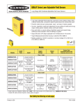
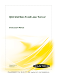
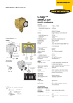
1
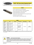
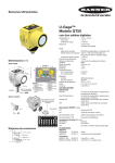
®
M-GAGE S18M
Vehicle Detection Sensor
Features
•
3-axis magnetoresistive-based technology; senses 3-dimensional changes to the
Earth’s magnetic field caused by the presence of ferrous objects
•
Easy sensor installation (see page 4); above- or below-ground mounting options
•
Compact, robust one-piece, self-contained sensor package replaces inductive-loop
sensing technology; no external controller needed
•
Designed to minimize the effects of temperature swings and destabilizing magnetic
fields
•
Sensor learns ambient background and stores settings in non-volatile memory
•
Patented technologies†
Models
Caution . . .
For Factory-Approved
Applications Only
Model
This sensor is to be used
only in factory-approved applications. See
warning on page 2, and list of approved
applications on page 3.
Cable*
2 m (6.5')
5-conductor
cable
S18MB
Supply
Voltage
10 to 30V dc
5-pin
Euro-style
QD fitting
S18MBQ
Output
Type
Bipolar
NPN/PNP**
Range
Range varies,
depending on
application and
target being sensed.
See Figures 5
and 6.
* 9 m cables are available by adding suffix “W/30” to the model number of any cabled sensor
(e.g., S18MB W/30). A model with a QD connector requires a mating cable; see page 8.
** Consult factory for other output options.
Approved Applications
See page 3 for more details on factory-approved applications
Car Wash Entry/Exit
WARNING . . .
Drive-Up Kiosk
Overhead Door
Loading Dock
Not To Be Used for Personnel Protection
Never use this product as a sensing device for personnel protection. Doing so could lead to serious injury or death.
This product does NOT include the self-checking redundant circuitry necessary to allow its use in personnel safety applications.
A sensor failure or malfunction can cause either an energized or de-energized sensor output condition. Consult your current Banner Safety
Products catalog for safety products which meet OSHA, ANSI and IEC standards for personnel protection.
†U.S. patent #6,546,344 B1
Printed in USA
10/03
P/N 114430 rev. A
®
M-GAGE S18M — Vehicle Detection Sensor
Overview
The M-GAGE S18M sensor implements a passive sensing technology to detect large
ferrous objects. The sensor measures the change in the Earth’s natural magnetic field
(the ambient magnetic field) caused by the introduction of a ferromagnetic object.
This easy-to-use sensor is extremely robust and is unaffected by dirt and moisture,
making it ideal for demanding outdoor environments. Simple programming
procedures provide flexibility for a variety of applications (see page 5).
Theory of Operation
The sensor uses three mutually perpendicular magnetoresistive transducers. Each
transducer detects magnetic field changes along one axis. By incorporating three
sensing elements, maximum sensor sensitivity is achieved.
A ferrous object will alter the local (ambient) magnetic field surrounding the object, as
shown in Figure 1. The magnitude of this magnetic field change is dependent both on
the object (its size, shape, orientation, and composition) and on the ambient magnetic
field (its strength and orientation).
A. Baseline magnetic field, with slight
disturbances caused by permanent
ferrous-metal objects within or near
the sensor, then . . .
During a simple programming procedure, the S18M sensor measures the ambient
magnetic field. When a large ferrous object (for example, a truck, automobile, or
rail car) alters that magnetic field, the sensor detects the magnetic field changes
(anomalies). When the degree of magnetic field change reaches the sensor’s
threshold, the sensor’s discrete outputs switch.
Sensor Field of View and Range
The sensor range depends on three variables:
1. The local magnetic environment (including nearby ferrous material)
2. The magnetic properties of the object to be sensed
3. Sensor settings
The S18M can detect changes in the ambient magnetic field in all directions. As with
other sensors, the range will depend on the target. The strong disturbance of a large
ferrous object decreases as distance from the sensor increases, and the magnitude
and shape of the disturbance is dependent on the object’s shape and content.
The sensor can be programmed to react to magnetic field disturbances of greater or
lesser intensity, using two adjustments: background condition and sensitivity level.
B. After a large steel target object is
introduced.
The sensor detects the differential
(magnetic strength and orientation)
between fields A and B. If the
differential is greater than the
sensitivity threshold, the sensor’s
outputs conduct.
Figure 1. Magnetic detection overview
Once background condition and sensitivity level are set, and both settings are stored
in non-volatile memory, the sensor is ready to detect the target object.
WARNING . . .
Appropriate Use
The mechanical opening, braking, and reversing systems of the door will not respond in sufficient time to prevent moving
trucks, cars, or material handling vehicles, even those traveling at low speeds, from coming in contact with the door. In
addition, the detection zone of the product may fluctuate due to changes in the local magnetic environment. All vehicles should
approach doors at speeds that allow the operator to ensure the door is operating properly and in an open position. Failure to follow these
procedures may result in serious injury or death.
Banner Engineering Corp. • Minneapolis, MN U.S.A.
2
P/N 114430 rev. A
www.bannerengineering.com • Tel: 763.544.3164
®
M-GAGE S18M — Vehicle Detection Sensor
Approved Applications
The M-GAGE sensor provides a direct replacement for inductive loop systems, and needs no external frequency controller box.
Unique mounting solutions allow an M-GAGE sensor to be replaced easily without disrupting or re-cutting the pavement.
Car Wash Entry/Exit
The Banner M-GAGE vehicle detection sensor will reliably
detect vehicles in and around car wash bays. It will
reliably detect the presence or absence of a vehicle to
provide collision avoidance at the exit of a conveyorized
tunnel, provide an entry or exit-door trigger, or trigger an
undercarriage wash.
Overhead Door
The Banner M-GAGE sensor can be used to trigger the
opening and closing of high-traffic internal overhead doors.
Mounted in the floor, it will reliably detect forklifts or trucks
as they approach the doors. Banner’s applications engineers
are available to help determine proper sensor placement for
specific door-trigger applications.
Drive-Up Kiosk
The Banner M-GAGE sensor reliably detects vehicles at
drive-through systems or other drive-up kiosks. It will
reliably detect a vehicle to trigger personnel that a vehicle
is present, and to initiate a timing system.
Loading Dock
The Banner M-GAGE sensor provides multiple advantages
for loading docks. It will reliably detect the presence of
a vehicle as it backs into a dock, triggering a light on the
interior of the building to notify the dock attendant that a
vehicle is in position for loading/unloading. The M-GAGE
can also be used to trigger dock/ramp leveling systems.
Banner Engineering Corp. • Minneapolis, MN U.S.A.
www.bannerengineering.com • Tel: 763.544.3164
P/N 114430 rev. A
3
®
M-GAGE S18M — Vehicle Detection Sensor
Below-Grade Installation
Materials
•
M-GAGE S18M Sensor
•
Above-Grade Installation
Materials
•
M-GAGE S18M Sensor
SMP1 Conduit Plug
•
SMP2 Conduit Plug
•
2" Schedule 80 rigid PVC conduit (1.5" may be used if there
is only one 90° bend); total length and number of elbows
depend on installation layout
•
3⁄4" Schedule 40 PVC electrical conduit; total length and
number of elbows depend on installation layout
•
2" (or 1.5") rigid PVC end cap (1 per installation)
•
Electrician’s fishtape
•
3⁄4" I.D. flexible, liquid-tight, non-metallic conduit (same
length as PVC conduit used for application)
•
Silicone adhesive
•
DPB1 Portable Programming Box
•
DPB1 Portable Programming Box
1.
3⁄4" Flex
Conduit
2.
2" PVC
Conduit
1.
2.
3⁄4" PVC Conduit
3.
6" Below
Grade
SMP1 Flex
Conduit Plug
Figure 2. Below-grade installation
Procedure
1) Lay out 2" (or 1.5") PVC in the desired configuration. For
the best sensor performance, the sensing location (located
at the end of the conduit run) should be 6" below the final
surface. Provide an access point where the PVC comes
above grade (where the sensor and flex conduit can be fed
in or pulled out, as required).
2) Secure the end cap to the PVC, at the sensing location.
3) Measure the overall length of the PVC run, from the
sensing location to the control panel.
4) Cut a section of 3⁄4" flex conduit to span the total distance
from the control panel to the sensing location.
5) Thread the sensor into the SMP1 conduit plug. Feed the
sensor cable into the flex conduit, until the sensor and plug
are snugly seated in the end of the flex conduit.
6) Feed the flex conduit by hand, sensor-end first, into the
PVC access point until the sensor reaches the PVC end cap.
SMP2 Conduit Plug
Figure 3. Above-grade installation
Procedure
1) Mount the PVC electrical conduit from the sensing point
to the control panel. Plastic conduit should be used for at
least the first 6.1 m (20') from the sensing point; metal or
flexible conduit may be used the remainder of the distance.
2) Thread the S18M sensor into the threads of the SMP2
conduit plug.
3) Feed the fishtape into the conduit, from the control panel
towards the sensing point.
4) Pull the sensor cable back through the conduit, until the
sensor almost reaches the end of the plastic conduit. Do
NOT pull sensor into conduit.
5) Apply a small amount of silicone adhesive to the outside of
the conduit at the sensing point end.
6) Press the conduit plug into the end of the conduit.
7) After the sensor is configured (see following section), wire
the sensor into the control device and power supply per the
wiring diagram on page 8.
7) Secure the remaining flex conduit from the access point to
the control cabinet.
8) After the sensor is configured (see following sections), wire
the sensor into the control device and power supply per the
wiring diagram on page 8.
Banner Engineering Corp. • Minneapolis, MN U.S.A.
4
P/N 114430 rev. A
www.bannerengineering.com • Tel: 763.544.3164
®
M-GAGE S18M — Vehicle Detection Sensor
Sensor Configuration
For most applications, configure the M-GAGE sensor remotely, via the DPB1 Portable
Programming Box, which provides programming access to an underground or
otherwise inaccessible sensor. For optimum performance, the sensor must be fixtured
so that it will not move either during or following configuration.
Power ON LED
Configuration/
Output ON LED
Push Button
Configuration using the sensor’s built-in push button is useful primarily for
demonstration and troubleshooting purposes.
Configuration via the DPB1 Portable Programming Box
Set Background Condition (No Vehicle Present)
Wire the M-GAGE sensor to the DPB1 as shown in Figure 4. Remove all vehicles and all other
metal objects temporarily in the sensing area, before setting the background condition.
Set
Background
Configuration
Brown Blue Gray White or Black
• “Click” the DPB1 TEACH push button once.
Result
• Sensor learns background.
• Output indicator LED flashes
approximately 12 times, while
background is taught.
• Sensor returns to RUN mode.
Set Sensitivity Level (6 sensitivity levels; level 1 least sensitive, level 6 most sensitive)
Test
Operation
Adjust Sensitivity
Sensitivity
Mode
Configuration
Result
• “Double-click” the DPB1 TEACH push button.
• Output LED flashes every 2 seconds;
sensor is at sensitivity level 1.
(When using the DPB1, the sensor
always reverts to sensitivity level 1.)
• To increase the sensitivity in increments,
“click” the push button again;
continue until desired
sensitivity level is reached.
• Output LED will flash from 1 to 6
times every 2 seconds to indicate
sensor’s sensitivity level (e.g., twice
to indicate level 2).
• “Double-click” push button
to save setting.
• Sensor returns to RUN mode
• Drive a vehicle past/over sensor to trip the
output; verify Output LED comes ON as
expected. Use a small/light vehicle to ensure
larger vehicles will be detected later.
PC
IR
“Single-Click” to Set Background
Condition
“Double-Click” to Set Sensitivity
Figure 4. Using the model DPB1 portable
programming box
Prepare for
Operation
• Adjust the sensitivity as needed.
• Disconnect DPB1 and hardwire sensor to
permanent power supply/output device (usersupplied). See page 8.
Configuration via the Sensor Push Button (For demonstration and troubleshooting only.)
Follow the instructions in the table above, with the following exceptions.
Set Background Condition (No Vehicle Present):
• Press and hold the push button for 2 seconds, until the Output LED turns red.
• Release, and then “click” the push button once.
Set Sensitivity Level:
• Press and hold the push button for 2 seconds, until the Output LED turns red.
• Release, and then quickly “double-click” the push button. Increase the sensitivity by
increments as described above.
• When the sensor is set to desired sensitivity level, double-click push button to return
sensor to RUN mode.
Banner Engineering Corp. • Minneapolis, MN U.S.A.
www.bannerengineering.com • Tel: 763.544.3164
P/N 114430 rev. A
5
®
M-GAGE S18M — Vehicle Detection Sensor
Excess Gain vs Sensitivity Level
(Assumes Level 5)
Excess Gain
Typical Target Excess Gain Curves
Level
Excess Gain Multiplier
1
0.33
2
0.4
3
0.5
4
0.66
5*
1.0
6
1.3
Once the sensor has been securely mounted and is configured, it is ready to operate.
The following two example applications show typical responses for the M-GAGE
sensor.
Example 1 describes mounting the M-GAGE 1 meter above the ground to sense an
automobile; see Figure 5. The graph in Figure 5 shows the excess gain for a typical
car. Excess gain is a measure of the amount of “extra” signal detected by the sensor
over and above the level needed to detect the target. This example assumes a level
5 sensitivity threshold. The table at right compares the change in excess gain if the
sensitivity level changes.
If the sensitivity is at level 6, then the excess gain at a given distance would be
1.3 times larger than for a level 5 sensitivity. Conversely, if the sensitivity threshold is
level 1, then the excess gain would be one third as big as for level 5.
*Factory default setting
Example 2 (see Figure 6) illustrates a typical vehicle passing over a sensor mounted
underground. Note that excess gain is greatest when the bulk of the vehicle (the rear
axle) is positioned directly over the sensor.
������
��������
��������
������������
8
Excess Gain
(Sensitivity Level 5)
7
���������
������
������������������������
���������������������
6
5
4
3
2
1
0
0
0.5 m
(1.6')
1.0 m
(3.2')
1.5 m
(4.8')
2.0 m
(6.4')
2.5 m
(8.0')
Distance from Vehicle Side
Figure 5. Application example 1: sensor mounted 1 meter (3.2') above ground
������
�����
��������
������
�����
�
�����
����
�����
����
�����
�����
�����
�����
�����
�����
�����
�����
�������������
�����������
���������
������
��������������������������
������
������
������������������������
���������������������
���������������������������������
������
�
�
�
�
�
�
�
������ ������ ������ ������ ���
����� ����� ����� �����
����� ����� ����� ����� ����� ����� ����� ����� ����� ����� ����� �����
����
����
����
���� ����� ����� ����� ����� ����� ����� ����� �����
����������������������������������
Figure 6. Application example 2: sensor mounted 0.25 meters (0.8') below ground
Banner Engineering Corp. • Minneapolis, MN U.S.A.
6
P/N 114430 rev. A
www.bannerengineering.com • Tel: 763.544.3164
®
M-GAGE S18M — Vehicle Detection Sensor
Specifications
Supply Voltage
10 to 30V dc (10% max. ripple) at 43 mA, exclusive of load
Above +50°C, supply voltage is 10 to 24V dc (10% max. ripple)
Sensing Range
See Figures 5 and 6.
Sensing Technology
Passive 3-axis magnetoresistive transducer
Supply Protection Circuitry
Protected against reverse polarity and transient voltages
Output Configuration
Two SPST solid-state outputs conduct when object is sensed; one NPN (current sinking) and one PNP (current
sourcing)
Output Protection
Protected against short-circuit conditions
Output Ratings
10 mA maximum (each output)
NPN saturation: < 200 mV @ 10 mA and < 600 mV @100 mA;
PNP saturation: < 1.2V @ 10 mA and < 1.6V @100 mA;
Output Response Time
20 milliseconds
Delay at Power-Up
0.5 seconds
Temperature Effect
< 0.5 milligauss/ °C
Adjustments
Configuration of Background Condition and Sensitivity Level may be set using the sensor’s push button or
remotely via the portable programming box (see page 5)
Indicators
Two indicators (see Figure 4 and instructions on page 5):
Power Indicator (Green)
Configuration/Output Indicator (Red/Yellow)
Remote TEACH Input
Impedance 12K ohms
Construction
Threaded Barrel: Thermoplastic polyester
Push Button: Santoprene
Operating Conditions
-40° to +70° C (-40° to +158° F); 100% max. rel. humidity
Connections
2 m or 9 m shielded 5-conductor (with drain) PVC jacketed attached cable or 5-pin Euro-style quick-disconnect
(see page 8 for quick-disconnect cable options)
Environmental rating
Leak proof design is rated IEC IP67; NEMA 6P
Vibration and Mechanical
Shock
All models meet Mil. Std. 202F requirements method 201A (vibration: 10 to 60Hz max., double amplitude 0.06",
maximum acceleration 10G). Also meets IEC 947-5-2: 30G 11 ms duration, half sine wave.
OFF-state leakage current: < 200 microamps
OFF-state leakage current: < 5 microamps
Push Button Housing: ABS/PC
Lightpipes: Acrylic
Dimensions
Cabled Model
Quick-Disconnect Model
�������
�������
�������
�������
�����
�������
�������
�������
�������
�������
�������
�������
������
�������
�������
�������
Banner Engineering Corp. • Minneapolis, MN U.S.A.
www.bannerengineering.com • Tel: 763.544.3164
P/N 114430 rev. A
7
®
M-GAGE S18M — Vehicle Detection Sensor
Hookups
Cabled Model
bn
bu
wh
bk
gy
Load
Load
Pin-out
Pin-Out
Quick-Disconnect Model
bn
bu
wh
Load
bk
Load
gy
+
10 - 30V dc
–
100 mA max. lo
Remote Progra
Shield
White Wi
+
10 - 30V dc
–
100 mA max. lo
Brown Wire
Blue Wire
Black Wire
Remote Progra
Gray Wir
Shield
Accessories
Model
Description
�������
�������
Conduit Plug for 3⁄4" flexible conduit,
used for below-grade installations
SMP1
�������
�������
38.1 mm
(1.50")
��
������
������
��
�����
�����
�������
�
�
�
�
�
�
�
�
�
�
�
�
�
�
�
�
�
�
�����������������
���������������
�
��
��
��
Handheld Portable Programming Box,
used for configuring sensor when
push button is not accessible
�������
�������
DPB1
� �
Conduit Plug for 3⁄4" rigid conduit, used
for above-grade installations
���������
SMP2
Ø 33.0 mm
(1.30")
Quick-Disconnect Cables
Style
5-Pin
Euro,
Straight
with
shield
Model
MQDEC2-506
MQDEC2-515
MQDEC2-530
Length
2 m (6.5')
5 m (15')
9 m (30')
Connector
Style
ø 15 mm
(0.6")
44 mm max.
(1.7")
M12 x 1
5-Pin
Euro,
Rightangle
with
shield
Model
Length
Connector
38 mm max.
(1.5")
MQDEC2-506RA
MQDEC2-515RA
MQDEC2-530RA
2 m (6.5')
5 m (15')
9 m (30')
38 mm max.
(1.5")
M12 x 1
ø 15 mm
(0.6")
WARRANTY:
Banner Engineering Corp. warrants its products to be free from defects for one year. Banner Engineering Corp. will repair or replace, free of
charge, any product of its manufacture found to be defective at the time it is returned to the factory during the warranty period. This warranty does not cover
damage or liability for the improper application of Banner products. This warranty is in lieu of any other warranty either expressed or implied.
P/N 114430 rev. A
Banner Engineering Corp., 9714 Tenth Ave. No., Minneapolis, MN USA 55441 • Phone: 763.544.3164 • www.bannerengineering.com • Email: [email protected]