1
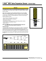
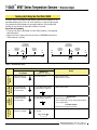
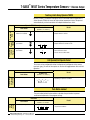
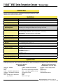
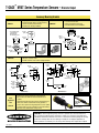
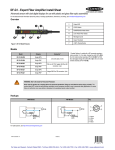
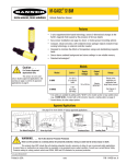
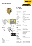
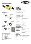
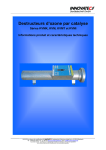
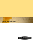
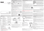
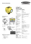
T-GAGE™ M18T Series Infrared Temperature Sensors
18 mm sensor with discrete output and TEACH-mode programming
Features
• Fast 25 ms response time (up to 20 Hz switching speed)
• Easy-to-use TEACH mode programming; no potentiometer adjustments
• Small self-contained package, no auxiliary controller needed
• Rugged encapsulated design for harsh environments
• Choose 2 meter or 9 meter unterminated cable, or 5-pin Euro-style QD connector
• Product motion not required for sensing
• Remote Teach available in both Static and Dynamic modes
Models
Model
Cable*
D:S Ratio
M18TB8
5-wire,
2 m (6.5') shielded cable
M18TB8Q
5-pin,
Euro-style integral QD
M18TB6E
5-wire,
2 m (6.5') shielded cable
M18TB6EQ
5-pin,
Euro-style integral QD
M18TB14
5-wire,
2 m (6.5') shielded cable
M18TB14Q
5-pin,
Euro-style integral QD
Sensing Face
8:1
Integrated lens
6:1
Enclosed Plastic
face (for food
industry use)
14:1
Germanium lens
Supply Voltage
Output
10 to 30V dc
Bipolar
(NPN and PNP)
*For 9 m (30') cable, add suffix “W/30” to the model number (e.g., M18TB8 W/30). A model with a QD connector requires an accessory mating cable. See page 7
for more information.
!
Printed in USA
WARNING . . .
Not To Be Used for Personnel Protection
Never use these products as sensing devices for personnel protection. Doing so could lead to serious injury or death.
These sensors do NOT include the self-checking redundant circuitry necessary to allow their use in personnel safety
applications. A sensor failure or malfunction can cause either an energized or de-energized sensor output condition.
Consult your current Banner Safety Products catalog for safety products which meet OSHA, ANSI and IEC standards for
personnel protection.
02/05
P/N 120632
T-GAGE™ M18T Series Temperature Sensors – Discrete Output
Overview
The T-GAGE sensor is a passive, non-contacting, temperature-based device. It is used
to detect object(s) that are either hotter or colder than the ambient condition, and then
activate an output.
While it looks and operates just like an Expert™ photoelectric sensor, the T-GAGE
detects the infrared light energy emitted by objects, instead of its own emitted light.
The sensor uses a thermopile detector, made up of multiple infrared-sensitive elements
(thermocouples) to detect this infrared energy within its field of view (see Figure 2).
Potential applications include:
• Hot part detection (baked goods, metals, bottles)
• Ejection verification of injection-molded parts
• Flame process verification
• Hot glue detection (packaging equipment, book binding, product assembly)
• Cold part detection (frozen foods, ice, dairy)
• Roller monitoring
�����������
���
��� ���
�����
����������������
���
�����
�����������
NOTE: The T-GAGE M18T sensor is not intended for absolute temperature
measurement or for safety-related fire detection use.
Sensing Field of View
The sensing range is determined by the sensor’s field of view (FOV), or viewing angle,
combined with the size of the object(s) being detected (see Figure 2). The sensor’s
distance-to-spot size ratio (D:S ratio) is inversely related to the viewing angle; a sensor
with a small viewing angle will have a large D:S ratio. The T-GAGE M18T sensors have
D:S ratios of 6:1, 8:1 or 14:1. For a sensor with an 8:1 D:S ratio, the sensor’s spot size
is a 1" diameter circle at a distance of 8"; farther from the sensor face the spot size will
be larger.
Figure 1. Sensor features
Spot Size
(see table)
Distance (mm)
200
400
600
800
1000
Distance From Sensor Face Versus Spot Size
Sensor
D:S Ratio
100
200
300
400
500
600
700
800
900
1000
6:1
17
33
50
67
83
100
117
133
150
167
8:1
13
25
38
50
63
75
88
100
113
125
14:1
7
14
21
29
36
43
50
57
64
71
Distance (mm)
Spot Size
(mm)
Figure 2. Detection spot size versus distance from sensor
2
P/N 120632
Banner Engineering Corp. • Minneapolis, MN U.S.A.
www.bannerengineering.com • Tel: 763.544.3164
T-GAGE™ M18T Series Temperature Sensors – Discrete Output
Apparent Temperature
Two factors that have a large influence on apparent temperature are the object’s
emissivity and whether or not the object fills the sensor’s field of view.
Object Emissivity: A “blackbody” is a “perfect” emitter, with an emissivity of 1.0 at all
temperatures and wavelengths. Most surfaces emit only a fraction of the amount of
thermal energy that a blackbody would. Typical T-GAGE applications will be sensing
objects with emissivities ranging from 0.5 to 0.95. Many references are available with
tables of emissivity coefficients for common materials. In general, shiny unpainted
metals have low emissivity, while non-glossy surfaces have high emissivity. Shiny
surfaces: a mirror or shiny surface can redirect an object’s emitted energy to an
undesired location, or even bring additional unintended thermal energy into the
sensor’s field of view (see page 6).
Object Size: If the object being detected does not fill the sensor’s field of view, then the
sensor will average the temperature of that object and whatever else is in the sensing
field of view. For the sensor to collect the maximum amount of energy, the object
should completely fill the sensor’s field of view. However, in some applications, when
the object is too small, this may not be possible. In such cases, if the object is hot
enough, the thermal contrast may still be adequate to trigger the sensor’s output.
Sensor Programming
Two TEACH methods may be used to program the sensor:
• Teach individual minimum and maximum limits (Two-Point Static Teach), or
• Dynamic Teach for on-the-fly programming.
The sensor may be programmed either via its push button, or via a remote switch.
Remote programming also may be used to disable the push button, preventing
unauthorized personnel from adjusting the programming settings. To access this
feature, connect a normally open switch between the sensor’s gray wire and dc
common or connect the gray wire to a digital input (PLC).
NOTE: The impedance of the Remote Teach input is 3 kΩ.
Programming is accomplished by following the sequence of input pulses (see
programming procedures starting on page 4). The duration of each pulse
(corresponding to a push button “click”), and the period between multiple pulses, are
defined as “T”:
0.04 seconds < T < 0.8 seconds
Status Indicators
Power ON/OFF LED
Indicates
OFF
Power is OFF
ON Green
Sensor is in Run mode
ON Red
TEACH is active
Output LED
Banner Engineering Corp. • Minneapolis, MN U.S.A.
www.bannerengineering.com • Tel: 763.544.3164
Indicates
OFF
Run Mode: Output is OFF
TEACH Mode: Waiting for Output OFF condition
ON Yellow
Run Mode: Outputs are energized
TEACH Mode: Waiting for Output ON condition
Flashing Yellow
Dynamic TEACH active
P/N 120632
3
T-GAGE™ M18T Series Temperature Sensors – Discrete Output
Teaching Limits Using Two-Point Static TEACH
Two-Point TEACH is the traditional setup method, used when two conditions can be
presented individually by the user. The sensor establishes a single sensing threshold
(the switchpoint) midway between the two taught conditions, with the Output ON
condition on one side and the Output OFF condition on the other.
General Notes on Programming
• The sensor will return to RUN mode if the first TEACH condition is not registered
within 60 seconds.
• After the first limit is taught, the sensor... will remain in PROGRAM mode until the
TEACH sequence is finished.
�����������������������������������������������
�����������������������������������������������
������������
�������������������
������������������
������������
�������������������
������������������
...
�����������
������������
���������
����
�����
����
...
���
���������
...
�����������
�����������
���������
D
���������
����������
���
�����
����
�����
������
����
�����������
�����������
���������
���
���������
�����������
������������
���������
���
�����
������
���������
����������
...
Figure 3. Two-Point Static Teach
D
or
Two-Point...TEACH Procedure
...
Learn
Output ON
Condition
Programming
Mode
D
Learn
Output OFF
Condition
(0.04 sec. < T < 0.8 sec.)
or
• Push and hold push
button for 2 seconds
• No action required
• Power LED turns Red
• Output LED turns Yellow
...
• Present Output
ON
T
condition and “Click”
the push button
T
Exit Without
Save
Result
Remote Line
Push Button
• Present Output OFF
condition and “Click”
the push button
D
T
T
•T Output
T LED turns OFF
T
T
T
T
T
T
T
T
T
T
T
T
• Hold remoteTline low for
2 seconds
P/N 120632
T
T
T
T
Teach Accepted
T LED turns Green
• Power
• Sensor
threshold
and
TT
TTautomatically sets the Tswitching
T
T
returns to Run mode
or
T
T
Teach Unacceptable
• Sensor returns to beginning of Teach
T
T
T
T
T
Sensor
returns
to RunTmode without saving new settings
T
T T
T
T
T
T
2 seconds
T
4
T
T
T
•T Present
T Output OFF condition
• Single-pulse the remote line
T
• Push and hold push
button for 2 seconds
or
•TPresent
Output ON conditionT
T
• Single-pulse the remote line
T
T
T
T
Banner Engineering Corp. • Minneapolis, MN U.S.A.
www.bannerengineering.com • Tel: 763.544.3164
T-GAGE™ M18T Series Temperature Sensors – Discrete Output
...
D
...
Teaching Limits Using Dynamic TEACH
Dynamic TEACH is a method of setting the sensor’s threshold while the application is
or high and low temperature limits of the process
active. Dynamic TEACH will sense the
and automatically set the threshold at the midpoint between these limits.
Dynamic TEACH Procedure
...
(0.04 sec. < T < 0.8 sec.)
...
• Push and hold push
button for 2 seconds
• No action required
• Power LED turns Red
• Output LED turns Yellow
Enter
Dynamic
TEACH
or
•...“Double-click”
push button
End Dynamic
TEACH
Process
Programming
Mode
Result
Remote Line
D
Push Button
• “Single-click”
push button
• Double-pulse the remote line
T
D
T
• Sensor begins dynamic learning process
• Output
LED
T Yellow @ 2 Hz
T
T flashes
T
T
T
• Single-pulse the remote line
• Sensor ends data collection; sets threshold
T
• Power
LED
T
T
T
T turns Green
• Sensor returns to Run mode
T
T
T
T
T
T
T
T
or
T
T
T
T
T
T
T
T
T
T
Hot Operate/Cold Operate Select
T
T
The sensor can be configured for either Hot Operate or Cold Operate via the remote
teach wire (gray). A series of three pulses
onT the line
T
T will
T toggle between Hot and Cold
Operation.
T
T
T
Procedure
Toggle Between
Hot Operate/
Cold Operate
T
T
• Triple-pulse the remote line
T
T
T
• Either Hot Operate or Cold Operate is selected,
depending on previous condition.
T
T
T
T
T
T
Push Button Lockout
T
T
T
T
Push Button
Push
Button
Lockout
(0.04 sec. < T < 0.8 sec.)
Not available via push button
T
Result
Remote Line
Push Button
T
T
The push button lockout feature enables or disables the push button to prevent
T
T
T
T
T
Tunauthorized adjustment of the program settings.
T
T
• Not available via push button
Banner Engineering Corp. • Minneapolis, MN U.S.A.
www.bannerengineering.com • Tel: 763.544.3164
T
T
T
Procedure
T
T
Remote
Line
T
T
Result
0.04 sec. < T < 0.8 sec.
• Four-pulse the remote line
T
T
T
T
T
T
• Push button is either enabled or disabled, depending
on previous condition.
T
P/N 120632
5
T-GAGE™ M18T Series Temperature Sensors – Discrete Output
Installation Notes
Align the sensor toward the object to be detected. Visually align if possible, or use the
alignment device accessory listed on page 8.
Specifications
Temperature Measurement Range
0° to 300° C (32° to 572° F) standard; custom ranges available
Sensing Range
Depends on object size and sensing field of view (see page 2)
Wavelength
8 to 14 µm
Distance to Spot Size (D:S) Ratio
8:1, 6:1, or 14:1, depending on model
Supply Voltage
10 to 30V dc (10% maximum ripple); 35 mA max (exclusive of load)
Output Configuration
One NPN (current sinking) and one PNP (current sourcing) in each model.
Output Protection
Protected against short circuit conditions
Output Ratings
100 mA maximum (each output)
OFF-state leakage current: NPN < 200 microamps; PNP < 10 microamps
NPN saturation: < 200 mV @ 10 mA and < 1V @ 100 mA
PNP saturation: < 1.2 V @ 10 mA and < 1.6V @ 100 mA
Output Response Time
25 ms
Delay at Power-Up
1.5 seconds
Repeatability (Relative)
1° C
Minimum Taught Differential
3° C
Hysteresis
5% of taught differential (minimum 1° C)
Adjustments
TEACH-Mode programming
Indicators
One bicolor (Green/Red) status LED, one Yellow LED (see page 3)
Remote Teach Input
Impedance: 3 kΩ
Construction
Threaded Barrel: 304 stainless steel
Push Button Housing: ABS/PC
Push Button: Santoprene
Lightpipes: Acrylic
Operating Conditions
Temperature: -20° to +70° C (-4° to 158° F)
Environmental Rating
Leakproof design is rated IEC IP67; NEMA 6
Temperature Warm-Up Time
5 minutes
Application Note
Following are examples of materials with high and low emissivity. (Many more examples can be found in sources such as the Internet.)
Sensor-Friendly Materials
(High Emissivity)
Aluminum – anodized
Asphalt
Brick
Carbon – lampblack or plate material
Cardboard – corrugated or chipboard
Concrete
Glass – smooth, lead, or borosilicate
(e.g., Pyrex®)
6
P/N 120632
Gypsum (including finished boards)
Ice
Iron and steel (except bright galvanized)
Paper – most types, regardless of color
Styrofoam® insulation
Plastics
Water
Wood – most types
Materials to Sense with Caution
(Low Emissivity – Test, Test, Test!)
Aluminum – plain or highly polished
Copper
Galvanized iron
Stainless steel
Vapor-deposited materials
Banner Engineering Corp. • Minneapolis, MN U.S.A.
www.bannerengineering.com • Tel: 763.544.3164
T-GAGE™ M18T Series Temperature Sensors – Discrete Output
Dimensions
Cabled Models
QD Models
������
�������
�������
�������
�������
�������
���������
������
�����
�������
���������
�������
�������
�������
���������������
���������������
����������������
����������������
��
��
����������������
���������������� ���������������
����������������� ���������������
����������������� ���������������
��
��
���������������
���������������
���������������
Hookups
Cabled Models
QD Models
��
��
��
��
��
��
����
����
������
������������
��
������������
��
����
��
����
��
������
�����
������
�����
������
NOTE: It is recommended that the shield wire be connected to earth ground or dc common.
Accessories
Quick-Disconnect Cables
Style
5-pin
Euro-style
straight, with
shield
Model
MQDEC2-506
MQDEC2-515
MQDEC2-530
Length
2 m (6.5')
5 m (15')
9 m (30')
Dimensions
Pinout
ø 15 mm
(0.6")
44 mm max.
(1.7")
M12 x 1
White
Brown
38 mm max.
(1.5")
5-pin
Euro-style
right-angle,
with shield
MQDEC2-506RA
MQDEC2-515RA
MQDEC2-530RA
2 m (6.5')
5 m (15')
9 m (30')
Blue
Black
Gray
38 mm max.
(1.5")
M12 x 1
ø 15 mm
(0.6")
Banner Engineering Corp. • Minneapolis, MN U.S.A.
www.bannerengineering.com • Tel: 763.544.3164
P/N 120632
7
T-GAGE™ M18T Series Temperature Sensors – Discrete Output
Accessory Mounting Brackets
• 12-gauge, stainless steel, right-angle
mounting bracket with a curved mounting
slot for versatility and orientation
• Clearance for M4 (#8) hardware
SMB18A
* Use 4 mm (#8) screws
to mount bracket.
Drill screw holes
24.2 mm (0.95") apart.
18.5 mm
(0.73")
30 mm
(1.2")
M18 x 1
internal
thread
41 mm
(1.6")
4.6 mm*
(0.18")
ø 4.6 mm*
(0.18")
36.0 mm
(1.42")
25.4 mm
(1.00")
30°
R 24.2 mm
(0.95")
42.0 mm
(1.65")
46 mm
(1.8")
������
�������
������
�������
�������
�������
�������
�������
���
���
�������
�������
�������
�������
��������
�������
��������������
�������
�������
�������
�������
�������
�������
�������
�������
�������
�������
�������
�������
�����������
LAT1812
������
�������
���������
�������
�������
�������
�������
�������
�������
������
���
�������
�������
�������
�������
SMB18A BRACKET
�������
�������
Laser
Alignment
Tool
25.4 mm
(1.00")
• 2-piece universal 18 mm swivel bracket
• 300 series stainless steel
• Includes stainless steel swivel locking hardware
��������
�������
�������
�������
22.9 mm
(0.9")
50.8 mm
(2.00")
�������
�������������
��������
�������
��������
�������
10.6 mm
(0.42")
7.6 mm
(0.30")
SMB18UR
�������
�������
• 18 mm swivel bracket
• Black thermoplastic polyester
• Includes stainless steel hardware
SMB18SF
������
�������
��������������
• Enables easy sensor alignment at long distances.
• Kit includes one SMB1812 bracket and M12 laser
emitter.
• Thread bracket housing onto barrel of mounted sensor;
M12 laser emitter inserted into housing provides a
precise laser spot for aiming temperature sensor. (Refer
to Banner data sheet p/n 122529 for more information.)
• Remove laser emitter before using sensor.
SMB1812
Bracket
Shown with
T-GAGE M18T
attached
M12 Laser Emitter
WARRANTY: Banner Engineering Corp. warrants its products to be free from defects for
one year. Banner Engineering Corp. will repair or replace, free of charge, any product of its
manufacture found to be defective at the time it is returned to the factory during the warranty
period. This warranty does not cover damage or liability for the improper application of
Banner products. This warranty is in lieu of any other warranty either expressed or implied.
P/N 120632
Banner Engineering Corp., 9714 Tenth Ave. No., Minneapolis, MN USA 55441 • Phone: 763.544.3164 • www.bannerengineering.com • Email: [email protected]