1
Part No. 311905-B Rev 00
December 2003
600 Technology Park Drive
Billerica, MA 01821-4130
Quad Serial PMC Module
Supplement
Copyright © 2003 Nortel Networks
All rights reserved. December 2003.
The information in this document is subject to change without notice. The statements, configurations, technical data,
and recommendations in this document are believed to be accurate and reliable, but are presented without express or
implied warranty. Users must take full responsibility for their applications of any products specified in this document.
The information in this document is proprietary to Nortel Networks Inc.
Trademarks
Nortel Networks, the Nortel Networks logo, the Globemark, Unified Networks, BayRS, and Passport are trademarks
of Nortel Networks.
Microsoft, Windows, and Windows NT are trademarks of Microsoft Corporation.
Adobe and Acrobat Reader are trademarks of Adobe Systems Incorporated.
The asterisk after a name denotes a trademarked item.
Statement of Conditions
In the interest of improving internal design, operational function, and/or reliability, Nortel Networks Inc. reserves the
right to make changes to the products described in this document without notice.
Nortel Networks Inc. does not assume any liability that may occur due to the use or application of the product(s) or
circuit layout(s) described herein.
USA Requirements Only
Federal Communications Commission (FCC) Compliance Notice: Radio Frequency Notice
Note: This equipment has been tested and found to comply with the limits for a Class A digital device, pursuant to
Part 15 of the FCC rules. These limits are designed to provide reasonable protection against harmful interference
when the equipment is operated in a commercial environment. This equipment generates, uses, and can radiate radio
frequency energy. If it is not installed and used in accordance with the instruction manual, it may cause harmful
interference to radio communications. Operation of this equipment in a residential area is likely to cause harmful
interference, in which case users will be required to take whatever measures may be necessary to correct the
interference at their own expense.
To maintain compliance with FCC radio frequency emission limits, shielded cables are required to connect equipment
to other Class A certified devices and the use of quadshield, RG-6/U type CATV cable is required for connection to
the CATV system. Any changes or modifications may void the user’s authorization to operate this equipment.
European Requirements Only
EN 55 022 Statement
This is to certify that the Nortel Networks quad serial PMC module is shielded against the generation of radio
interference in accordance with the application of Council Directive 89/336/EEC, Article 4a. Conformity is declared
by the application of EN 55 022 Class A (CISPR 22).
Warning: This is a Class A product. In a domestic environment, this product may cause radio interference, in which
case, the user may be required to take appropriate measures.
Achtung: Dieses ist ein Gerät der Funkstörgrenzwertklasse A. In Wohnbereichen können bei Betrieb dieses Gerätes
Rundfunkstörungen auftreten, in welchen Fällen der Benutzer für entsprechende Gegenmaßnahmen verantwortlich
ist.
Attention: Ceci est un produit de Classe A. Dans un environnement domestique, ce produit risque de créer des
interférences radioélectriques, il appartiendra alors à l’utilisateur de prendre les mesures spécifiques appropriées.
ii
311905-B Rev 00
EC Declaration of Conformity
This product conforms (or these products conform) to the provisions of the R&TTE Directive 1999/5/EC.
Japan/Nippon Requirements Only
Voluntary Control Council for Interference (VCCI) Statement
Taiwan Requirements
Bureau of Standards, Metrology and Inspection (BSMI) Statement
Canada Requirements Only
Canadian Department of Communications Radio Interference Regulations
This digital apparatus (Quad Serial PMC Module) does not exceed the Class A limits for radio-noise emissions from
digital apparatus as set out in the Radio Interference Regulations of the Canadian Department of Communications.
Règlement sur le brouillage radioélectrique du ministère des Communications
Cet appareil numérique (Quad Serial PMC Module) respecte les limites de bruits radioélectriques visant les appareils
numériques de classe A prescrites dans le Règlement sur le brouillage radioélectrique du ministère des
Communications du Canada.
311905-B Rev 00
iii
Nortel Networks Inc. Software License Agreement
This Software License Agreement (“License Agreement”) is between you, the end-user (“Customer”) and Nortel
Networks Corporation and its subsidiaries and affiliates (“Nortel Networks”). PLEASE READ THE FOLLOWING
CAREFULLY. YOU MUST ACCEPT THESE LICENSE TERMS IN ORDER TO DOWNLOAD AND/OR USE
THE SOFTWARE. USE OF THE SOFTWARE CONSTITUTES YOUR ACCEPTANCE OF THIS LICENSE
AGREEMENT. If you do not accept these terms and conditions, return the Software, unused and in the original
shipping container, within 30 days of purchase to obtain a credit for the full purchase price.
“Software” is owned or licensed by Nortel Networks, its parent or one of its subsidiaries or affiliates, and is
copyrighted and licensed, not sold. Software consists of machine-readable instructions, its components, data,
audio-visual content (such as images, text, recordings or pictures) and related licensed materials including all whole or
partial copies. Nortel Networks grants you a license to use the Software only in the country where you acquired the
Software. You obtain no rights other than those granted to you under this License Agreement. You are responsible for
the selection of the Software and for the installation of, use of, and results obtained from the Software.
1. Licensed Use of Software. Nortel Networks grants Customer a nonexclusive license to use a copy of the
Software on only one machine at any one time or to the extent of the activation or authorized usage level, whichever is
applicable. To the extent Software is furnished for use with designated hardware or Customer furnished equipment
(“CFE”), Customer is granted a nonexclusive license to use Software only on such hardware or CFE, as applicable.
Software contains trade secrets and Customer agrees to treat Software as confidential information using the same care
and discretion Customer uses with its own similar information that it does not wish to disclose, publish or disseminate.
Customer will ensure that anyone who uses the Software does so only in compliance with the terms of this Agreement.
Customer shall not a) use, copy, modify, transfer or distribute the Software except as expressly authorized; b) reverse
assemble, reverse compile, reverse engineer or otherwise translate the Software; c) create derivative works or
modifications unless expressly authorized; or d) sublicense, rent or lease the Software. Licensors of intellectual
property to Nortel Networks are beneficiaries of this provision. Upon termination or breach of the license by
Customer or in the event designated hardware or CFE is no longer in use, Customer will promptly return the Software
to Nortel Networks or certify its destruction. Nortel Networks may audit by remote polling or other reasonable means
to determine Customer’s Software activation or usage levels. If suppliers of third party software included in Software
require Nortel Networks to include additional or different terms, Customer agrees to abide by such terms provided by
Nortel Networks with respect to such third party software.
2. Warranty. Except as may be otherwise expressly agreed to in writing between Nortel Networks and Customer,
Software is provided “AS IS” without any warranties (conditions) of any kind. NORTEL NETWORKS DISCLAIMS
ALL WARRANTIES (CONDITIONS) FOR THE SOFTWARE, EITHER EXPRESS OR IMPLIED, INCLUDING,
BUT NOT LIMITED TO THE IMPLIED WARRANTIES OF MERCHANTABILITY AND FITNESS FOR A
PARTICULAR PURPOSE AND ANY WARRANTY OF NON-INFRINGEMENT. Nortel Networks is not obligated
to provide support of any kind for the Software. Some jurisdictions do not allow exclusion of implied warranties, and,
in such event, the above exclusions may not apply.
3. Limitation of Remedies. IN NO EVENT SHALL NORTEL NETWORKS OR ITS AGENTS OR SUPPLIERS
BE LIABLE FOR ANY OF THE FOLLOWING: a) DAMAGES BASED ON ANY THIRD PARTY CLAIM; b)
LOSS OF, OR DAMAGE TO, CUSTOMER’S RECORDS, FILES OR DATA; OR c) DIRECT, INDIRECT,
SPECIAL, INCIDENTAL, PUNITIVE, OR CONSEQUENTIAL DAMAGES (INCLUDING LOST PROFITS OR
SAVINGS), WHETHER IN CONTRACT, TORT OR OTHERWISE (INCLUDING NEGLIGENCE) ARISING OUT
OF YOUR USE OF THE SOFTWARE, EVEN IF NORTEL NETWORKS, ITS AGENTS OR SUPPLIERS HAVE
BEEN ADVISED OF THEIR POSSIBILITY. The forgoing limitations of remedies also apply to any developer and/or
supplier of the Software. Such developer and/or supplier is an intended beneficiary of this Section. Some jurisdictions
do not allow these limitations or exclusions and, in such event, they may not apply.
iv
311905-B Rev 00
4.
General
a.
If Customer is the United States Government, the following paragraph shall apply: All Nortel Networks
Software available under this License Agreement is commercial computer software and commercial
computer software documentation and, in the event Software is licensed for or on behalf of the United States
Government, the respective rights to the software and software documentation are governed by Nortel
Networks standard commercial license in accordance with U.S. Federal Regulations at 48 C.F.R. Sections
12.212 (for non-DoD entities) and 48 C.F.R. 227.7202 (for DoD entities).
b.
Customer may terminate the license at any time. Nortel Networks may terminate the license if Customer
fails to comply with the terms and conditions of this license. In either event, upon termination, Customer
must either return the Software to Nortel Networks or certify its destruction.
c.
Customer is responsible for payment of any taxes, including personal property taxes, resulting from
Customer’s use of the Software. Customer agrees to comply with all applicable laws including all applicable
export and import laws and regulations.
d.
Neither party may bring an action, regardless of form, more than two years after the cause of the action
arose.
e.
The terms and conditions of this License Agreement form the complete and exclusive agreement between
Customer and Nortel Networks.
f.
This License Agreement is governed by the laws of the country in which Customer acquires the Software. If
the Software is acquired in the United States, then this License Agreement is governed by the laws of the
state of New York.
311905-B Rev 00
v
Contents
Preface
Before You Begin .............................................................................................................xiii
Text Conventions .............................................................................................................xiv
Acronyms .........................................................................................................................xiv
Hard-Copy Technical Manuals ......................................................................................... xv
How to Get Help .............................................................................................................. xv
Chapter 1
Using the Quad Serial PMC Module
Verifying Passport 5430 Requirements ..........................................................................1-2
Installing the Quad Serial PMC Module ..........................................................................1-2
Attaching Cables ............................................................................................................1-6
Interpreting LEDs ...........................................................................................................1-8
Completing Software Configuration ................................................................................1-8
Appendix A
Cables and Interface Specifications
Cabling .......................................................................................................................... A-1
Serial Interface Pin Assignments ................................................................................... A-3
311905-B Rev 00
vii
Figures
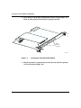
Figure 1-1.
Quad Serial PMC Module ........................................................................1-1
Figure 1-2.
Removing the PMC Module Filler Panel ..................................................1-3
Figure 1-3.
Installing the Quad Serial PMC Module ...................................................1-4
Figure 1-4.
Securing the PMC Module to the Expansion Card ..................................1-5
Figure 1-5.
120-pin to Quad 44-pin Adapter Assembly ..............................................1-6
Figure 1-6.
Quad Serial PMC Module Cable Connection ...........................................1-7
Figure 1-7.
Quad Serial PMC Module LEDs ..............................................................1-8
Figure A-1.
Quad Serial PMC Module Interface ........................................................ A-3
311905-B Rev 00
ix
Tables
Table 1-1.
Diagnostic and Boot Code for the Quad Serial PMC Module ..................1-2
Table A-1.
Quad Serial PMC Cable Requirements ................................................. A-2
Table A-2.
Signal and Pin Assignments for Port 1 ................................................... A-4
Table A-3.
Signal and Pin Assignments for Port 2 ................................................... A-5
Table A-4.
Signal and Pin Assignments for Port 3 ................................................... A-7
Table A-5.
Signal and Pin Assignments for Port 4 ................................................... A-9
311905-B Rev 00
xi
Preface
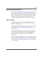
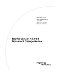
The quad serial PMC provides connectivity over the WAN. The quad serial
interface supports four full-duplex synchronous (HDLC), asynchronous, and
bisynchronous serial ports.
In this guide, the Passport* 5430 Multiservice Access Switch is referred to as the
Passport 5430.
Before You Begin
This guide is intended for qualified service personnel who are installing the
Passport 5430 for the first time or who need to install or replace any Passport 5430
customer-replaceable unit (CRU). A qualified service person should have
appropriate technical training and experience and be aware of the hazards
involved in installing and replacing CRUs.
Before installing the quad serial PMC module into the Passport 5430, make sure
that all network wiring has been installed on the premises using standard
cable-system practices.
Before turning on the Passport 5430 for the first time, contact your network
administrator to determine which software configuration option to use.
Note: The Passport 5430 Quad Serial PMC Module can be installed only on
the expansion card (Part No. DU0004001).
311905-B Rev 00
xiii
Quad Serial PMC Module Supplement
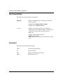
Text Conventions
This guide uses the following text conventions:
bold text
Indicates command names and options and text that
you need to enter.
Example: Enter show ip {alerts | routes}.
Example: Use the dinfo command.
italic text
Indicates new terms, book titles, and variables in
command syntax descriptions. Where a variable is two
or more words, the words are connected by an
underscore.
Example: If the command syntax is:
show at <valid_route>
valid_route is one variable and you substitute one value
for it.
Acronyms
This guide uses the following acronyms:
xiv
CRU
customer-replaceable unit
IP
Internet Protocol
PCI
peripheral component interconnect
PMC
PCI mezzanine card
311905-B Rev 00
Preface
Hard-Copy Technical Manuals
You can print selected technical manuals and release notes free, directly from the
Internet. Go to the www.nortelnetworks.com/documentation URL. Find the
product for which you need documentation. Then locate the specific category and
model or version for your hardware or software product. Use Adobe* Acrobat
Reader* to open the manuals and release notes, search for the sections you need,
and print them on most standard printers. Go to Adobe Systems at the
www.adobe.com URL to download a free copy of the Adobe Acrobat Reader.
How to Get Help
If you purchased a service contract for your Nortel Networks product from a
distributor or authorized reseller, contact the technical support staff for that
distributor or reseller for assistance.
If you purchased a Nortel Networks service program, contact Nortel Networks
Technical Support. To obtain contact information online, go to the
www.nortelnetworks.com/cgi-bin/comments/comments.cgi URL, then click on
Technical Support.
From the Technical Support page, you can open a Customer Service Request
online or find the telephone number for the nearest Technical Solutions Center.
If you are not connected to the Internet, you can call 1-800-4NORTEL
(1-800-466-7835) to learn the telephone number for the nearest Technical
Solutions Center.
An Express Routing Code (ERC) is available for many Nortel Networks products
and services. When you use an ERC, your call is routed to a technical support
person who specializes in supporting that product or service. To locate an ERC for
your product or service, go to the http://www.nortelnetworks.com/help/contact/
erc/index.html URL.
311905-B Rev 00
xv
Chapter 1
Using the Quad Serial PMC Module
This document supplements Installing and Operating the Passport 5430
Multiservice Access Switch. Follow the hardware installation steps in that manual,
then refer to this document for information specific to the quad serial PMC
module.
Quad
Serial
1
3
2
4
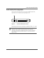
Warning: The quad serial module is designed to operate in the
Passport 5430 Multiservice Access Switch only. Attempting to use the quad
serial PMC module in any other product may be hazardous and invalidates the
regulatory approval.
FBR0117A
Figure 1-1.
311905-B Rev 00
Quad Serial PMC Module
1-1
Quad Serial PMC Module Supplement
Verifying Passport 5430 Requirements
Table 1-1 shows the programmable read-only memory (PROM) boot and
diagnostic code required to use the quad serial.
Table 1-1.
Diagnostic and Boot Code for the Quad Serial PMC Module
Code Type
Version
Directory
File Name
Boot
15.4.2.0
fbr_proms
pp5430boot.exe
Diagnostic
1.16
diag.a
pmc_0060.a
qscop_ram-ere 1.00
scop_rom.exe 1.00
pp5430_ram.exe ver 1.5
The .exe files are found in the flash card.
Note: The version numbers of the boot and diagnostic code for your Passport
5430 must match the version numbers shown in Table 1-1. If the code versions
of your switch are earlier than these, you must upgrade the PROM code.
Failure to do so may cause the Passport 5430 to not operate correctly. For
information about verifying, and upgrading PROM code, see the BayRS*
Upgrading Routers guide.
Installing the Quad Serial PMC Module
To install a PMC module on the expansion card:
1.
Attach an antistatic wrist strap, one end of the strap to your wrist and the
other end to the router chassis.
Caution: Electrostatic discharge can damage hardware. You must wear the
antistatic wrist strap whenever you handle printed circuit boards. The strap
directs static electricity from your body to the router chassis, preventing
discharge to sensitive electronic components. You receive an antistatic wrist
strap with the system processor module. See the instructions included with the
wrist strap.
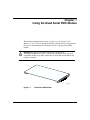
2.
1-2
If the expansion card slot contains a filler panel, push it out from behind
the card bezel (Figure 1-2).
311905-B Rev 00
Using the Quad Serial PMC Module
Ex
pa
ns
ion
rd
Ca
FBR0058A
Figure 1-2.
3.
311905-B Rev 00
Removing the PMC Module Filler Panel
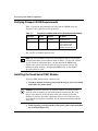
Holding the quad serial PMC module with the connectors facing down,
slide it into the opening on the expansion card (Figure 1-3).
1-3
Quad Serial PMC Module Supplement
4.
Press down to seat the PMC module firmly into the sockets (Figure 1-3).
Make sure the gasket on the faceplate is properly inserted.
rd
Ca
ion
s
an
p
Ex
PMC
module
openings
FBR0006A
Figure 1-3.
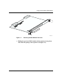
5.
1-4
Installing the Quad Serial PMC Module
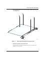
Flip the expansion card upside down so that the side with the expansion
card is facing down (Figure 1-4).
311905-B Rev 00
Using the Quad Serial PMC Module
Insert and tighten the screws to secure the PMC module to the expansion
card (Figure 1-4).
ns
pa
Ex
6.
rd
Ca
ion
FBR0007
Figure 1-4.
7.
Securing the PMC Module to the Expansion Card
Install the expansion card into the chassis.
For instructions, see Installing an Expansion Card in the Passport 5430
Multiservice Access Switch.
311905-B Rev 00
1-5
Quad Serial PMC Module Supplement
Attaching Cables
This quad serial interface supports multiple WAN protocols at a maximum
transmission rate of 2 Mbps.This section describes how you connect a cable to the
120-pin interface on the installed adapter module. See Appendix A for more cable
and interface information.
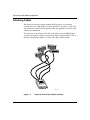
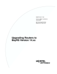
To connect up to four 44-pin serial cables to the 5430 quad serial PMC module,
you must first connect a 120-pin to quad 44-pin adapter assembly (P/N 311158-A,
Order No. DU0011009) (Figure 1-5). This cable ships with the module.
PORT 3
T4
POR
T1
POR
CAB0115A
Figure 1-5.
1-6
120-pin to Quad 44-pin Adapter Assembly
311905-B Rev 00
Using the Quad Serial PMC Module
For more information about which 44-pin serial cable to use, see “Cabling” on
page A-1.
To connect the serial interface cable to the quad serial interface:
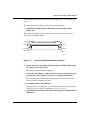
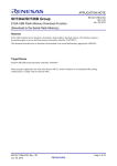
1.
Connect the 120-pin portion of the 120-pin to quad 44-pin adapter
(Figure 1-6).
This quad serial adapter cable is required to connect up to four 44-pin cables
to the quad serial PMC modules.
Pin 30
Pin 1
Pin 60
Pin 31
Pin 90
Pin 61
Pin 120
Pin 91
CAB0116A
Figure 1-6.
2.
Quad Serial PMC Module Cable Connection
Secure the quad serial adapter cable to the interface PMC module using
the captive screws on the cable.
The screws should be tightened completely.
3.
Locate the serial interface cables and connect one to each end of the quad
serial adapter cable. Make sure the screws are tightened completely.
The serial interfaces automatically configure the desired electrical interface
when used with standard keyed cables.
4.
Arrange the cable in the cable loom.
For instructions, see “Using the Cable Looms to Manage Cables” in Installing
and Operating the Passport 5430 Multiservice Access Switch.
5.
311905-B Rev 00
Connect the remote end of each cable to the appropriate communications
equipment.
1-7
Quad Serial PMC Module Supplement
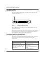
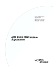
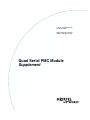
Interpreting LEDs
The quad serial PMC module has four green LEDs to indicate the status of the
individual ports (Figure 1-7).
LEDs
Quad
Serial
1
3
2
4
FBR0116A
Figure 1-7.
Quad Serial PMC Module LEDs
When an LED is lit, the associated port is active. When the LED is not lit, the
associated port is inactive.
When you power up the Passport 5430, the LEDs will blink in a counter clockwise
pattern. This indicates the onboard processor has completed and is waiting for
boot and diagnostic commands from the Passport 5430 host.
Completing Software Configuration
Once you have successfully installed the quad serial PMC module, complete the
following software configuration tasks using instructions found in the
documentation:
Configuration Task
Location of Instructions
If this is a first time installation, you must
quick-start your Passport 5430.
Installing and Operating the Passport 5430
Multiservice Access Switch
Modify the Passport 5430 configuration file
to add the quad serial PMC module and
enable default quad serial PMC module
software services.
•
•
•
1-8
Configuring and Managing Routers with
Site Manager
Using the Bay Command Console
(BCC)
Configuring TDM Services
311905-B Rev 00
Using the Quad Serial PMC Module
Note: Adding software for the quad serial PMC module may increase the
router’s memory requirements beyond its current capacity. If the Passport 5430
experiences a memory problem, see the section “Memory or Buffer Problem”
in Troubleshooting Routers. For information about changing the router image,
see Configuring and Managing Routers with Site Manager.
For the latest information, be sure to review the release notes and documentation
change notice for your version of BayRS software.
311905-B Rev 00
1-9
Appendix A
Cables and Interface Specifications
Cabling
The quad serial interface supports four serial ports. Each serial port is an
independent asynchronous/synchronous communication port capable of operating
at speeds up to 2 Mbps. With the appropriate cabling, each port can operate in
either a DTE or DCE configuration while supporting the following interfaces:
311905-B Rev 00
•
EIA-449
•
EIA-530
•
V.28
•
V.35
•
RS-232
•
X.21
A-1
Quad Serial PMC Module Supplement
The cables listed in Table A-1 are designed to support these interfaces.
Note: Old sychronous cables will not work properly with the quad serial card.
Table A-1.
A-2
Quad Serial PMC Cable Requirements
Cable
Description
Part No.
Model No.
EIA-232 DTE cable
(standard)
Straight-thru 44-Pin male to DB-25 311137-A
male
AA0018049
EIA-232 DCE cable
Crossover 44-pin male to DB-25
female
311128-A
AA0018041
RS-422 DTE cable
Straight-thru 44-Pin male to DB-37 311140-A
male
AA0018052
RS-422 DCE cable
Crossover 44-Pin male to DB-37
female
311129-A
AA0018042
EIA-530 DTE cable
Straight-thru 44-Pin male to DB-25 311144-A
male
AA0018054
EIA-530 DCE cable
Crossover 44-Pin male to DB-25
female
311130-A
AA0018043
V.28 DTE cable
Straight-thru 44-Pin male to DB-25 311147-A
male
AA0018057
V.28 DCE cable
Crossover 44-pin male to DB-25
female
311131-A
AA0018044
V.35 DTE cable
Straight-thru 44-pin male to 34-pin 311150-A
male
AA0018060
V.35 DCE cable
Crossover 44-pin male to 34-pin
female
311132-A
AA0018045
X.21 DTE cable
Straight-thru 44-pin male to 15-pin 311153-A
or DB-15 male
AA0018063
X.21 DCE cable
Crossover 44-pin male to 15-pin or 311133-A
DB-15 female
AA0018046
311905-B Rev 00
Cables and Interface Specifications
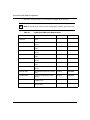
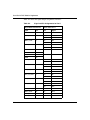
Serial Interface Pin Assignments
You can connect four 44-pin cables to each quad serial PMC module. This
requires the use of a 120-pin to quad 44-pin adapter cable.
LEDs
Quad
Serial
1
3
Figure of 120-pin interface
2
4
FBR0116A
Figure A-1.
Quad Serial PMC Module Interface
The following tables show the signal and pin assignment for Ports 1, 2, 3, and 4.
Caution: The following data is intended for informational use only. Due to the
complexity of this assembly, Nortel Networks does not recommend
construction of this adapter assembly by the end user. Incorrect wiring may
cause damage to the quad serial PMC module. Use only Nortel Networks
approved cables.
311905-B Rev 00
A-3
Quad Serial PMC Module Supplement
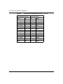
Table A-2 shows the signal and pin assignments for Port 1.
Table A-2.
Signal and Pin Assignments for Port 1
120-pin QSerial Connector
44 Pin Conn Port 1
Signal
Pin
Pin
Signal
FGND
16
1
FGND
PORT1_TXD+
8
2
SD+
38
VSD+
16
SD-
36
VSD-
17
RD-
37
VRD-
7
SGND
43
SGND
11
RT+
34
VRT+
25
RT-
33
VRT-
10
ST+
32
VST+
24
ST-
31
VST-
12
TT+
40
VTT+
26
TT-
39
VTT-
PORT1_TXD-
PORT1_RXD+
7
35
SGND
3
SGND
9
SGND
13
SGND
34
PORT1_RT+
2
PORT1_RT-
PRT1_TT_DCE+
PRT1_TT_DCE-
PRT1_TT_DTE+
PRT1_TT_DTE-
1
4
5
33
32
PORT1_DTR+
41
8
DTR+
PORT1_DTR-
42
22
DTR-
PORT1_DSR+
39
6
DSR+
PORT1_DSR-
38
20
DSR(continued)
A-4
311905-B Rev 00
Cables and Interface Specifications
Table A-2.
Signal and Pin Assignments for Port 1 (continued)
120-pin QSerial Connector
44 Pin Conn Port 1
Signal
Pin
Pin
Signal
PORT1_DCD+
43
9
DCD+
PORT1_DCD-
44
23
DCD-
PORT1_RTS+
14
4
RTS+
PORT1_RTS-
15
18
RTS-
PORT1_CTS+
10
5
CTS+
PORT1_CTS-
11
19
CTS-
PORT1_CMD
12
27
CMD
PRT1_MODE1
31
41
MODE1
PRT1_MODE2
6
42
MODE2
PRT1_MODE3
37
21
MODE3
SGND
40
44
SGND
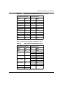
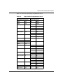
Table A-3 shows the signal and pin assignment for Port 2.
Table A-3.
Signal and Pin Assignments for Port 2
120-pin QSerial Connector
44 Pin Conn Port 2
Signal
Pin
Pin
Signal
FGND
76
1
FGND
PORT2_TXD+
68
2
SD+
38
VSD+
16
SD-
36
VSD-
3
RD+
37
VRD+
17
RD-
35
VRD-
7
SGND
PORT2_TXD-
PORT2_RXD+
PORT2_RXD-
67
95
96
SGND
63
SGND
69
(continued)
311905-B Rev 00
A-5
Quad Serial PMC Module Supplement
Table A-3.
120-pin QSerial Connector
44 Pin Conn Port 2
Signal
Pin
Pin
Signal
SGND
73
43
SGND
SGND
94
PORT2_RT+
62
11
RT+
34
VRT+
25
RT-
33
VRT-
10
ST+
32
VST+
24
ST-
31
VST-
12
TT+
40
VTT+
26
TT-
39
VTT-
PORT2_RT-
PRT2_TT_DCE+
PRT2_TT_DCE-
PRT2_TT_DTE+
PRT2_TT_DTE-
A-6
Signal and Pin Assignments for Port 2 (continued)
61
64
65
93
92
PORT2_DTR+
101
8
DTR+
PORT2_DTR-
102
22
DTR-
PORT2_DSR+
99
6
DSR+
PORT2_DSR-
98
20
DSR-
PORT2_DCD+
103
9
DCD+
PORT2_DCD-
104
23
DCD-
PORT2_RTS+
74
4
RTS+
PORT2_RTS-
75
18
RTS-
PORT2_CTS+
70
5
CTS+
PORT2_CTS-
71
19
CTS-
PORT2_CMD
72
27
CMD
PRT2_MODE1
91
41
MODE1
PRT2_MODE2
66
42
MODE2
PRT2_MODE3
97
21
MODE3
SGND
100
44
SGND
311905-B Rev 00
Cables and Interface Specifications
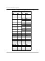
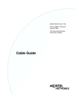
Table A-4 shows the signal and pin assignment for Port 3.
Table A-4.
Signal and Pin Assignments for Port 3
120-pin QSerial Connector
44 Pin Conn Port 3
Signal
Pin
Pin
Signal
FGND
60
1
FGND
PORT3_TXD+
24
2
SD+
38
VSD+
16
SD-
36
VSD-
3
RD+
37
VRD+
17
RD-
35
VRD-
7
SGND
43
SGND
11
RT+
34
VRT+
25
RT-
33
VRT-
10
ST+
32
VST+
24
ST-
31
VST-
12
TT+
40
VTT+
26
TT-
39
VTT-
PORT3_TXD-
PORT3_RXD+
PORT3_RXD-
23
49
50
SGND
19
SGND
25
SGND
29
SGND
48
PORT3_RT+
18
PORT3_RT-
PRT3_TT_DCE+
PRT3_TT_DCE-
PRT3_TT_DTE+
PRT3_TT_DTE-
17
20
21
47
46
PORT3_DTR+
55
8
DTR+
PORT3_DTR-
56
22
DTR(continued)
311905-B Rev 00
A-7
Quad Serial PMC Module Supplement
Table A-4.
A-8
Signal and Pin Assignments for Port 3 (continued)
120-pin QSerial Connector
44 Pin Conn Port 3
Signal
Pin
Pin
Signal
PORT3_DSR+
53
6
DSR+
PORT3_DSR-
52
20
DSR-
PORT3_DCD+
57
9
DCD+
PORT3_DCD-
58
23
DCD-
PORT3_RTS+
28
4
RTS+
PORT3_RTS-
30
18
RTS-
PORT3_CTS+
26
5
CTS+
PORT3_CTS-
27
19
CTS-
PORT3_CMD
59
27
CMD
PRT3_MODE1
45
41
MODE1
PRT3_MODE2
22
42
MODE2
PRT3_MODE3
51
21
MODE3
SGND
54
44
SGND
311905-B Rev 00
Cables and Interface Specifications
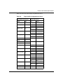
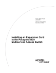
Table A-5 shows the signal and pin assignment for Port 4.
Table A-5.
Signal and Pin Assignments for Port 4
120-pin QSerial Connector
44 Pin Conn Port 4
Signal
Pin
Pin
Signal
FGND
120
1
FGND
PORT4_TXD+
84
2
SD+
38
VSD+
16
SD-
36
VSD-
3
RD+
37
VRD+
17
RD-
35
VRD-
7
SGND
43
SGND
11
RT+
34
VRT+
25
RT-
33
VRT-
10
ST+
32
VST+
24
ST-
31
VST-
12
TT+
40
VTT+
26
TT-
39
VTT-
PORT4_TXD-
PORT4_RXD+
PORT4_RXD-
83
109
110
SGND
79
SGND
85
SGND
89
SGND
108
PORT4_RT+
78
PORT4_RT-
PRT4_TT_DCE+
PRT4_TT_DCE-
PRT4_TT_DTE+
PRT4_TT_DTE-
77
80
81
107
106
PORT4_DTR+
115
8
DTR+
PORT4_DTR-
116
22
DTR(continued)
311905-B Rev 00
A-9
Quad Serial PMC Module Supplement
Table A-5.
A-10
Signal and Pin Assignments for Port 4 (continued)
120-pin QSerial Connector
44 Pin Conn Port 4
Signal
Pin
Pin
Signal
PORT4_DSR+
113
6
DSR+
PORT4_DSR-
112
20
DSR-
PORT4_DCD+
117
9
DCD+
PORT4_DCD-
118
23
DCD-
PORT4_RTS+
88
4
RTS+
PORT4_RTS-
90
18
RTS-
PORT4_CTS+
86
5
CTS+
PORT4_CTS-
87
19
CTS-
PORT4_CMD
119
27
CMD
PRT4_MODE1
105
41
MODE1
PRT4_MODE2
82
42
MODE2
PRT4_MODE3
111
21
MODE3
SGND
114
44
SGND
311905-B Rev 00