1
Part No. 302283-E Rev 00
August 2001
600 Technology Park Drive
Billerica, MA 01821-4130
Installing Hardware Options
for the Contivity VPN Switch
2
Copyright © 2001 Nortel Networks
All rights reserved. August 2001.
The information in this document is subject to change without notice. The statements, configurations, technical data, and
recommendations in this document are believed to be accurate and reliable, but are presented without express or implied
warranty. Users must take full responsibility for their applications of any products specified in this document. The
information in this document is proprietary to Nortel Networks Inc.
The software described in this document is furnished under a license agreement and may be used only in accordance
with the terms of that license. The software license agreement is included in this document.
Trademarks
Nortel Networks, the Nortel Networks logo, the Globemark, Unified Networks, and Contivity are trademarks of Nortel
Networks.
Microsoft, Windows, and Windows NT and MS-DOS are trademarks of Microsoft Corporation.
Adobe and Acrobat Reader are trademarks of Adobe Systems Incorporated.
Restricted rights legend
Use, duplication, or disclosure by the United States Government is subject to restrictions as set forth in subparagraph
(c)(1)(ii) of the Rights in Technical Data and Computer Software clause at DFARS 252.227-7013.
Notwithstanding any other license agreement that may pertain to, or accompany the delivery of, this computer software,
the rights of the United States Government regarding its use, reproduction, and disclosure are as set forth in the
Commercial Computer Software-Restricted Rights clause at FAR 52.227-19.
Statement of conditions
In the interest of improving internal design, operational function, and/or reliability, Nortel Networks Inc. reserves the
right to make changes to the products described in this document without notice.
Nortel Networks Inc. does not assume any liability that may occur due to the use or application of the product(s) or
circuit layout(s) described herein.
Portions of the code in this software product may be Copyright © 1988, Regents of the University of California. All
rights reserved. Redistribution and use in source and binary forms of such portions are permitted, provided that the above
copyright notice and this paragraph are duplicated in all such forms and that any documentation, advertising materials,
and other materials related to such distribution and use acknowledge that such portions of the software were developed
by the University of California, Berkeley. The name of the University may not be used to endorse or promote products
derived from such portions of the software without specific prior written permission.
SUCH PORTIONS OF THE SOFTWARE ARE PROVIDED “AS IS” AND WITHOUT ANY EXPRESS OR IMPLIED
WARRANTIES, INCLUDING, WITHOUT LIMITATION, THE IMPLIED WARRANTIES OF MERCHANTABILITY
AND FITNESS FOR A PARTICULAR PURPOSE.
In addition, the program and information contained herein are licensed only pursuant to a license agreement that contains
restrictions on use and disclosure (that may incorporate by reference certain limitations and notices imposed by third
parties).
302283-E Rev 00
3
USA requirements only
Federal Communications Commission (FCC) Compliance Notice: Radio Frequency Notice
Note: This equipment has been tested and found to comply with the limits for a Class A digital device, pursuant to
Part 15 of the FCC rules. These limits are designed to provide reasonable protection against harmful interference when
the equipment is operated in a commercial environment. This equipment generates, uses, and can radiate radio frequency
energy. If it is not installed and used in accordance with the instruction manual, it may cause harmful interference to
radio communications. Operation of this equipment in a residential area is likely to cause harmful interference, in which
case users will be required to take whatever measures may be necessary to correct the interference at their own expense.
European requirements only
EN 55 022 statement (Class A)
This is to certify that the Nortel Networks Contivity VPN Switch is shielded against the generation of radio interference
in accordance with the application of Council Directive 89/336/EEC, Article 4a. Conformity is declared by the
application of EN 55 022 Class A (CISPR 22).
Warning: This is a Class A product. In a domestic environment, this product may cause radio interference, in which
case, the user may be required to take appropriate measures.
Achtung: Dieses ist ein Gerät der Funkstörgrenzwertklasse A. In Wohnbereichen können bei Betrieb dieses Gerätes
Rundfunkstörungen auftreten, in welchen Fällen der Benutzer für entsprechende Gegenmaßnahmen verantwortlich ist.
Attention: Ceci est un produit de Classe A. Dans un environnement domestique, ce produit risque de créer des
interférences radioélectriques, il appartiendra alors à l’utilisateur de prendre les mesures spécifiques appropriées.
To maintain compliance with FCC radio frequency emission limits, shielded cables are required to connect equipment to
other Class A certified devices and the use of quadshield, RG-6/U type CATV cable is required for connection to the
CATV system. Any changes or modifications may void the user’s authorization to operate this equipment.
EN 55 022 statement (Class B)
This is to certify that the Nortel Networks Contivity 1600 and 2600 are shielded against the generation of radio
interference in accordance with the application of Council Directive 89/336/EEC, Article 4a. Conformity is declared by
the application of EN 55 022 Class B (CISPR 22).
Compliance is dependent upon the use of shielded Nortel Networks Contivity 1600 or 2600.
EC Declaration of Conformity
Tthese products conform to the provisions of the R&TTE Directive 1999/5/EC.
Installing Hardware Options for the Contivity VPN Switch
4
Japan/Nippon requirements only
Voluntary Control Council for Interference (VCCI) statement (Class A)
Voluntary Control Council for Interference (VCCI) statement (Class B Contivity 1600 and 2600)
Taiwan requirements
Bureau of Standards, Metrology and Inspection (BSMI) statement
Canada requirements only
Canadian Department of Communications Radio Interference Regulations
This digital apparatus (Contivity VPN Switch) does not exceed the Class A limits for radio-noise emissions from digital
apparatus as set out in the Radio Interference Regulations of the Canadian Department of Communications.
Règlement sur le brouillage radioélectrique du ministère des Communications
Cet appareil numérique (Contivity VPN Switch) respecte les limites de bruits radioélectriques visant les appareils
numériques de classe A prescrites dans le Règlement sur le brouillage radioélectrique du ministère des Communications
du Canada.
302283-E Rev 00
5
Canadian Department of Communications Radio Interference Regulations
This digital apparatus (Contivity 1600 and Contivity 2600) does not exceed the Class B limits for radio-noise
emissions from digital apparatus as set out in the Radio Interference Regulations of the Canadian Department of
Communications.
Règlement sur le brouillage radioélectrique du ministère des Communications (Classe B)
Cet appareil numérique (Contivity 1600 and Contivity 2600) respecte les limites de bruits radioélectriques visant
les appareils numériques de classe B prescrites dans le Règlement sur le brouillage radioélectrique du ministère des
Communications du Canada.
Canada CS-03 rules and regulations
Notice: The Industry Canada label identifies certified equipment. This certification means that the equipment meets
telecommunications network protective, operational and safety requirements as prescribed in the appropriate
Terminal Equipment Technical Requirements document(s). The Department does not guarantee the equipment will
operate to the user’s satisfaction.
Before installing this equipment, users should ensure that it is permissible to be connected to the facilities of the
local telecommunications company. The equipment must also be installed using an acceptable method of
connection. The customer should be aware that compliance with the above conditions may not prevent the
degradation of service in some situations.
Repairs to certified equipment should be coordinated by a representative designated by the supplier. Any repairs or
alterations made by the user to this equipment, or equipment malfunctions, may give the telecommunications
company cause to request the user to disconnect the equipment.
Users should ensure for their own protection that the electrical ground connections of the power utility, telephone
lines and internal metallic water pipe system, if present, are connected together. This precaution may be particularly
important in rural areas.
Caution: Users should not attempt to make such connections themselves, but should contact the appropriate
electric inspection authority, or electrician, as appropriate.
Notice: For equipment using loopstart lines, please note that the Ringer Equivalence Number (REN) assigned to
each terminal device provides an indication of the maximum number of terminals allowed to be connected to a
telephone interface. The termination on an interface may consist of any combination of devices subject only to the
requirement that the sum of the Ringer Equivalence Numbers of all the devices does not exceed 5. The REN is
located on the “FCC Rules Part 68” label located on the bracket of the module, or on the back of the unit.
Canada CS-03 -- règles et règlements
Avis: L'étiquette d'Industrie Canada identifie le matériel homologué. Cette étiquette certifie que le matériel est
conforme aux normes de protection, d'exploitation et de sécurité des réseaux de télécommunications, comme le
prescrivent les documents concernant les exigences techniques relatives au matériel terminal. Le Ministère n'assure
toutefois pas que le matériel fonctionnera à la satisfaction de l'utilisateur.
Avant d'installer ce matériel, l'utilisateur doit s'assurer qu'il est permis de le raccorder aux installations de
l'entreprise locale de télécommunication. Le matériel doit également être installé en suivant une méthode acceptée
de raccordement. L'abonné ne doit pas oublier qu'il est possible que la conformité aux conditions énoncées
ci-dessus n'empêche pas la dégradation du service dans certaines situations.
Les réparations de matériel homologué doivent être coordonnées par un représentant désigné par le fournisseur.
L'entreprise de télécommunications peut demander à l'utilisateur de débrancher un appareil à la suite de réparations
ou de modifications effectuées par l'utilisateur ou à cause de mauvais fonctionnement.
Installing Hardware Options for the Contivity VPN Switch
6
Pour sa propre protection, l'utilisateur doit s'assurer que tous les fils de mise à la terre de la source d'énergie
électrique, des lignes téléphoniques et des canalisations d'eau métalliques, s'il y en a, sont raccordés ensemble.
Cette précaution est particulièrement importante dans les régions rurales.
Avertissement: L'utilisateur ne doit pas tenter de faire ces raccordements lui-même; il doit avoir recours à un
service d'inspection des installations électriques, ou à un électricien, selon le cas.
Avis: Veuillez prendre note que pour tout appareillage supportant des lignes de type “loopstart,” l'indice
d'équivalence de la sonnerie (IES) assigné à chaque dispositif terminal indique le nombre maximal de terminaux
qui peuvent être raccordés à une interface. La terminaison d'une interface téléphonique peut consister en une
combinaison de quelques dispositifs, à la seule condition que la somme d'indices d'équivalence de la sonnerie de
tous les dispositifs n'excède pas 5. Le REN figure sur l’étiquette “FCC Rules Part 68” située sur le support du
module ou à l’arrière de l’unité.
FCC Part 68 compliance statement
This equipment complies with Part 68 of FCC Rules. All direct connections to telephone network lines must be made
using standard plugs and jacks compliant with FCC Part 68. Please note the following:
1. You are required to request service from the telephone company before you connect the unit to a network. When you
request service, you must provide the telephone company with the following data:
•
When you request T1 Service, you must provide the telephone company with
—
The Facility Interface Code
Provide the telephone company with all the codes below:
–
–
–
–
–
04DU9-BN (1.544 MB, D4 framing format)
04DU9-DN (1.544 MB, D4 framing format with B8ZF coding)
04DU9-1KN (1.544 MB, ESF framing format)
04DU9-1SN (1.544 MB, ESF framing format with B8ZF coding)
04DU9-1ZN (1.544 MB, ANSI ESF and ZBTSI without line power)
The telephone company will select the code it has available.
•
•
—
The Service Order Code(s) (SOC): 6.0Y
—
The required Universal Service Order Code (USOC) jack: RJ48C
When you request ISDN “U” Interface Service, you must provide the telephone company with
—
The Facility Interface Code: 02IS5
—
The Service Order Code(s) (SOC): 6.0F
—
The required Universal Service Order Code (USOC) jack: RJ49C
When you request ISDN “S/T” Interface Service, you must provide the telephone company with
—
The Service Order Code(s) (SOC): 6.0P
—
The make, model number, and FCC Registration number of the NT1
Note: ISDN S/T cannot be directly connected to the network.
•
When you request Primary Rate ISDN Service, you must provide the telephone company with
—
The Facility Interface Code: 04DU9-1SN (1.544 MB, ESF framing format with B8ZF coding)
—
The Service Order Code(s) (SOC): 6.0Y
—
The required Universal Service Order Code (USOC) jack: RJ48C
302283-E Rev 00
7
2. Your telephone company may make changes to its facilities, equipment, operations, or procedures that could affect
the proper functioning of your equipment. The telephone company will notify you in advance of such changes to
give you an opportunity to maintain uninterrupted telephone service.
3. If the unit causes harm to the telephone network, the telephone company may temporarily discontinue your service.
If possible, they will notify you in advance, but if advance notice is not practical, you will be notified as soon as
possible and will be informed of your right to file a complaint with the FCC.
4. If you experience trouble with the unit, please contact the Nortel Networks Technical Solutions Center in your area
for service or repairs. Repairs should be performed only by service personnel authorized by Nortel Networks.
North America
(800) 4NORTEL or (800) 466-7835
EMEA
(33) (4) 92-966-968
Asia Pacific
(61) (2) 9927-8800
China
(800) 810-5000
5. You are required to notify the telephone company when you disconnect the unit from the network.
Nortel Networks Inc. software license agreement
NOTICE: Please carefully read this license agreement before copying or using the accompanying software or installing
the hardware unit with pre-enabled software (each of which is referred to as “Software” in this Agreement). BY
COPYING OR USING THE SOFTWARE, YOU ACCEPT ALL OF THE TERMS AND CONDITIONS OF THIS
LICENSE AGREEMENT. THE TERMS EXPRESSED IN THIS AGREEMENT ARE THE ONLY TERMS UNDER
WHICH NORTEL NETWORKS WILL PERMIT YOU TO USE THE SOFTWARE. If you do not accept these terms
and conditions, return the product, unused and in the original shipping container, within 30 days of purchase to obtain a
credit for the full purchase price.
1. License grant. Nortel Networks Inc. (“Nortel Networks”) grants the end user of the Software (“Licensee”) a personal,
nonexclusive, nontransferable license: a) to use the Software either on a single computer or, if applicable, on a single
authorized device identified by host ID, for which it was originally acquired; b) to copy the Software solely for backup
purposes in support of authorized use of the Software; and c) to use and copy the associated user manual solely in
support of authorized use of the Software by Licensee. This license applies to the Software only and does not extend to
Nortel Networks Agent software or other Nortel Networks software products. Nortel Networks Agent software or other
Nortel Networks software products are licensed for use under the terms of the applicable Nortel Networks Inc. Software
License Agreement that accompanies such software and upon payment by the end user of the applicable license fees for
such software.
2. Restrictions on use; reservation of rights. The Software and user manuals are protected under copyright laws.
Nortel Networks and/or its licensors retain all title and ownership in both the Software and user manuals, including any
revisions made by Nortel Networks or its licensors. The copyright notice must be reproduced and included with any
copy of any portion of the Software or user manuals. Licensee may not modify, translate, decompile, disassemble, use
for any competitive analysis, reverse engineer, distribute, or create derivative works from the Software or user manuals
or any copy, in whole or in part. Except as expressly provided in this Agreement, Licensee may not copy or transfer the
Software or user manuals, in whole or in part. The Software and user manuals embody Nortel Networks’ and its
licensors’ confidential and proprietary intellectual property. Licensee shall not sublicense, assign, or otherwise disclose
to any third party the Software, or any information about the operation, design, performance, or implementation of the
Software and user manuals that is confidential to Nortel Networks and its licensors; however, Licensee may grant
permission to its consultants, subcontractors, and agents to use the Software at Licensee’s facility, provided they have
agreed to use the Software only in accordance with the terms of this license.
3. Limited warranty. Nortel Networks warrants each item of Software, as delivered by Nortel Networks and properly
installed and operated on Nortel Networks hardware or other equipment it is originally licensed for, to function
substantially as described in its accompanying user manual during its warranty period, which begins on the date
Software is first shipped to Licensee. If any item of Software fails to so function during its warranty period, as the sole
Installing Hardware Options for the Contivity VPN Switch
8
remedy Nortel Networks will at its discretion provide a suitable fix, patch, or workaround for the problem that may be
included in a future Software release. Nortel Networks further warrants to Licensee that the media on which the
Software is provided will be free from defects in materials and workmanship under normal use for a period of 90 days
from the date Software is first shipped to Licensee. Nortel Networks will replace defective media at no charge if it is
returned to Nortel Networks during the warranty period along with proof of the date of shipment. This warranty does not
apply if the media has been damaged as a result of accident, misuse, or abuse. The Licensee assumes all responsibility
for selection of the Software to achieve Licensee’s intended results and for the installation, use, and results obtained
from the Software. Nortel Networks does not warrant a) that the functions contained in the software will meet the
Licensee’s requirements, b) that the Software will operate in the hardware or software combinations that the Licensee
may select,
c) that the operation of the Software will be uninterrupted or error free, or d) that all defects in the operation of the
Software will be corrected. Nortel Networks is not obligated to remedy any Software defect that cannot be reproduced
with the latest Software release. These warranties do not apply to the Software if it has been (i) altered, except by
Nortel Networks or in accordance with its instructions; (ii) used in conjunction with another vendor’s product, resulting
in the defect; or (iii) damaged by improper environment, abuse, misuse, accident, or negligence. THE FOREGOING
WARRANTIES AND LIMITATIONS ARE EXCLUSIVE REMEDIES AND ARE IN LIEU OF ALL OTHER
WARRANTIES EXPRESS OR IMPLIED, INCLUDING WITHOUT LIMITATION ANY WARRANTY OF
MERCHANTABILITY OR FITNESS FOR A PARTICULAR PURPOSE. Licensee is responsible for the security of its
own data and information and for maintaining adequate procedures apart from the Software to reconstruct lost or altered
files, data, or programs.
4. Limitation of liability. IN NO EVENT WILL NORTEL NETWORKS OR ITS LICENSORS BE LIABLE FOR
ANY COST OF SUBSTITUTE PROCUREMENT; SPECIAL, INDIRECT, INCIDENTAL, OR CONSEQUENTIAL
DAMAGES; OR ANY DAMAGES RESULTING FROM INACCURATE OR LOST DATA OR LOSS OF USE OR
PROFITS ARISING OUT OF OR IN CONNECTION WITH THE PERFORMANCE OF THE SOFTWARE, EVEN IF
NORTEL NETWORKS HAS BEEN ADVISED OF THE POSSIBILITY OF SUCH DAMAGES. IN NO EVENT
SHALL THE LIABILITY OF NORTEL NETWORKS RELATING TO THE SOFTWARE OR THIS AGREEMENT
EXCEED THE PRICE PAID TO NORTEL NETWORKS FOR THE SOFTWARE LICENSE.
5. Government licensees. This provision applies to all Software and documentation acquired directly or indirectly by or
on behalf of the United States Government. The Software and documentation are commercial products, licensed on the
open market at market prices, and were developed entirely at private expense and without the use of any U.S.
Government funds. The license to the U.S. Government is granted only with restricted rights, and use, duplication, or
disclosure by the U.S. Government is subject to the restrictions set forth in subparagraph (c)(1) of the Commercial
Computer Software––Restricted Rights clause of FAR 52.227-19 and the limitations set out in this license for civilian
agencies, and subparagraph (c)(1)(ii) of the Rights in Technical Data and Computer Software clause of DFARS
252.227-7013, for agencies of the Department of Defense or their successors, whichever is applicable.
6. Use of software in the European Community. This provision applies to all Software acquired for use within the
European Community. If Licensee uses the Software within a country in the European Community, the Software
Directive enacted by the Council of European Communities Directive dated 14 May, 1991, will apply to the examination
of the Software to facilitate interoperability. Licensee agrees to notify Nortel Networks of any such intended
examination of the Software and may procure support and assistance from Nortel Networks.
7. Term and termination. This license is effective until terminated; however, all of the restrictions with respect to
Nortel Networks’ copyright in the Software and user manuals will cease being effective at the date of expiration of the
Nortel Networks copyright; those restrictions relating to use and disclosure of Nortel Networks’ confidential information
shall continue in effect. Licensee may terminate this license at any time. The license will automatically terminate if
Licensee fails to comply with any of the terms and conditions of the license. Upon termination for any reason, Licensee
will immediately destroy or return to Nortel Networks the Software, user manuals, and all copies. Nortel Networks is not
liable to Licensee for damages in any form solely by reason of the termination of this license.
8. Export and re-export. Licensee agrees not to export, directly or indirectly, the Software or related technical data or
information without first obtaining any required export licenses or other governmental approvals. Without limiting the
foregoing, Licensee, on behalf of itself and its subsidiaries and affiliates, agrees that it will not, without first obtaining all
302283-E Rev 00
9
Contents
Preface . . . . . . . . . . . . . . . . . . . . . . . . . . . . . . . . . . . . . . . . . . . . . . . . . . . . . . 13
Related publications . . . . . . . . . . . . . . . . . . . . . . . . . . . . . . . . . . . . . . . . . . . . . . . . . . . 14
Text conventions . . . . . . . . . . . . . . . . . . . . . . . . . . . . . . . . . . . . . . . . . . . . . . . . . . . . . . 14
Acronyms . . . . . . . . . . . . . . . . . . . . . . . . . . . . . . . . . . . . . . . . . . . . . . . . . . . . . . . . . . . 16
Hard-copy technical manuals . . . . . . . . . . . . . . . . . . . . . . . . . . . . . . . . . . . . . . . . . . . . 17
How to get help . . . . . . . . . . . . . . . . . . . . . . . . . . . . . . . . . . . . . . . . . . . . . . . . . . . . . . 17
Chapter 1
Contivity 4600 Option Installation . . . . . . . . . . . . . . . . . . . . . . . . . . . . . . . . 19
Opening the Contivity 4600 . . . . . . . . . . . . . . . . . . . . . . . . . . . . . . . . . . . . . . . . . . . . . 19
Contivity 4600 system board layout . . . . . . . . . . . . . . . . . . . . . . . . . . . . . . . . . . . . . . . 22
Installing Contivity 4600 LAN/WAN and hardware accelerator cards . . . . . . . . . . . . . 23
Installing Contivity 4600 DIMMs . . . . . . . . . . . . . . . . . . . . . . . . . . . . . . . . . . . . . . . . . . 24
Replacing a Contivity 4600 power supply . . . . . . . . . . . . . . . . . . . . . . . . . . . . . . . . . . 25
Replacing a Contivity 4600 hard disk drive . . . . . . . . . . . . . . . . . . . . . . . . . . . . . . . . . 27
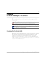
Chapter 2
Contivity 4500 Option Installation . . . . . . . . . . . . . . . . . . . . . . . . . . . . . . . . 31
Opening the Contivity 4500 . . . . . . . . . . . . . . . . . . . . . . . . . . . . . . . . . . . . . . . . . . . . . 31
Removing the Contivity 4500 front bezel . . . . . . . . . . . . . . . . . . . . . . . . . . . . . . . . 31
Contivity 4500 system board layout . . . . . . . . . . . . . . . . . . . . . . . . . . . . . . . . . . . . . . . 34
Installing Contivity 4500 LAN/WAN and hardware accelerator option cards . . . . . . . . 36
Installing Contivity 4500 DIMMs . . . . . . . . . . . . . . . . . . . . . . . . . . . . . . . . . . . . . . . . . . 38
Replacing a Contivity 4500 power supply . . . . . . . . . . . . . . . . . . . . . . . . . . . . . . . . . . 40
Replacing a Contivity 4500 hard disk drive . . . . . . . . . . . . . . . . . . . . . . . . . . . . . . . . . 41
Chapter 3
Contivity 2500/2000/4000 Option Installation . . . . . . . . . . . . . . . . . . . . . . . 43
Opening the Contivity 2500/2000/4000 . . . . . . . . . . . . . . . . . . . . . . . . . . . . . . . . . . . . 43
Removing the Contivity 2500/2000/4000 front bezel . . . . . . . . . . . . . . . . . . . . . . . 43
Removing the Contivity 2500/2000/4000 top cover . . . . . . . . . . . . . . . . . . . . . . . . 45
Contivity 2500/2000/4000 system board layout . . . . . . . . . . . . . . . . . . . . . . . . . . . . . . 46
Installing Hardware Options for the Contivity VPN Switch
10
Installing Contivity 2500/2000/4000 LAN/WAN option cards . . . . . . . . . . . . . . . . . . . . 48
Installing Contivity 2500/2000/4000 DIMMs . . . . . . . . . . . . . . . . . . . . . . . . . . . . . . . . . 49
Replacing a Contivity 4000 power supply . . . . . . . . . . . . . . . . . . . . . . . . . . . . . . . . . . 50
Replacing a Contivity 4000 disk drive . . . . . . . . . . . . . . . . . . . . . . . . . . . . . . . . . . . . . 52
Installing Contivity 2500/2000/4000 DIMMs . . . . . . . . . . . . . . . . . . . . . . . . . . . . . . . . . 54
Memory option . . . . . . . . . . . . . . . . . . . . . . . . . . . . . . . . . . . . . . . . . . . . . . . . . . . . . . . 55
Chapter 4
Contivity 2600 Option Installation . . . . . . . . . . . . . . . . . . . . . . . . . . . . . . . . 57
Opening the Contivity 2600 . . . . . . . . . . . . . . . . . . . . . . . . . . . . . . . . . . . . . . . . . . . . . 57
Removing the Contivity 2600 front bezel . . . . . . . . . . . . . . . . . . . . . . . . . . . . . . . . 58
Removing the Contivity 2600 top cover . . . . . . . . . . . . . . . . . . . . . . . . . . . . . . . . . 59
Contivity 2600 system board layout . . . . . . . . . . . . . . . . . . . . . . . . . . . . . . . . . . . . . . . 60
Installing LAN/WAN and hardware accelerator option cards . . . . . . . . . . . . . . . . . . . . 62
Installing Contivity 2600 DIMMs . . . . . . . . . . . . . . . . . . . . . . . . . . . . . . . . . . . . . . . . . . 64
Memory option . . . . . . . . . . . . . . . . . . . . . . . . . . . . . . . . . . . . . . . . . . . . . . . . . . . . . . . 65
Chapter 5
Contivity 1600 Option Installation . . . . . . . . . . . . . . . . . . . . . . . . . . . . . . . . 67
Opening the Contivity 1600 . . . . . . . . . . . . . . . . . . . . . . . . . . . . . . . . . . . . . . . . . . . . . 67
Removing the Contivity 1600 front bezel . . . . . . . . . . . . . . . . . . . . . . . . . . . . . . . . 68
Removing the Contivity 1600 top cover . . . . . . . . . . . . . . . . . . . . . . . . . . . . . . . . . 69
Contivity 1600 system board layout . . . . . . . . . . . . . . . . . . . . . . . . . . . . . . . . . . . . . . . 71
Installing Contivity 1600 option cards . . . . . . . . . . . . . . . . . . . . . . . . . . . . . . . . . . . . . . 72
Installing Contivity 1600 DIMMs . . . . . . . . . . . . . . . . . . . . . . . . . . . . . . . . . . . . . . . . . . 75
Memory option . . . . . . . . . . . . . . . . . . . . . . . . . . . . . . . . . . . . . . . . . . . . . . . . . . . . . . . 76
Chapter 6
Contivity 600 Option Installation . . . . . . . . . . . . . . . . . . . . . . . . . . . . . . . . . 77
Opening the Contivity 600 . . . . . . . . . . . . . . . . . . . . . . . . . . . . . . . . . . . . . . . . . . . . . . 78
Contivity 600 system board layout . . . . . . . . . . . . . . . . . . . . . . . . . . . . . . . . . . . . . . . . 80
Installing Contivity 600 option cards . . . . . . . . . . . . . . . . . . . . . . . . . . . . . . . . . . . . . . . 81
Memory option . . . . . . . . . . . . . . . . . . . . . . . . . . . . . . . . . . . . . . . . . . . . . . . . . . . . . . . 83
Index . . . . . . . . . . . . . . . . . . . . . . . . . . . . . . . . . . . . . . . . . . . . . . . . . . . . . . . . 85
302283-E Rev 00
11
Figures
Figure 1
Removing the Contivity 4600 front bezel . . . . . . . . . . . . . . . . . . . . . . . . . 20
Figure 2
Contivity 4600 front components . . . . . . . . . . . . . . . . . . . . . . . . . . . . . . . 21
Figure 3
Sample Contivity 4600 system board . . . . . . . . . . . . . . . . . . . . . . . . . . . . 22
Figure 4
Installing Contivity 4600 LAN/WAN and hardware accelerator cards . . . . 23
Figure 5
Installing Contivity 4600 DIMMs . . . . . . . . . . . . . . . . . . . . . . . . . . . . . . . . 25
Figure 6
Removing a Contivity 4600 power supply . . . . . . . . . . . . . . . . . . . . . . . . . 26
Figure 7
Removing a Contivity 4600 hard disk drive . . . . . . . . . . . . . . . . . . . . . . . 28
Figure 8
Removing the Contivity 4500 front bezel . . . . . . . . . . . . . . . . . . . . . . . . . 32
Figure 9
Contivity 4500 front components . . . . . . . . . . . . . . . . . . . . . . . . . . . . . . . 33
Figure 10
Sample Contivity 4500 system board . . . . . . . . . . . . . . . . . . . . . . . . . . . . 35
Figure 11
Installing 4500 LAN/WAN and hardware accelerator option cards . . . . . . 37
Figure 12
Installing Contivity 4500 DIMMs . . . . . . . . . . . . . . . . . . . . . . . . . . . . . . . . 38
Figure 13
Removing a Contivity 4500 power supply . . . . . . . . . . . . . . . . . . . . . . . . . 40
Figure 14
Removing a Contivity 4500 hard disk drive . . . . . . . . . . . . . . . . . . . . . . . 42
Figure 15
Removing the Contivity 2500/2000/4000 front bezel . . . . . . . . . . . . . . . . 44
Figure 16
Removing the Contivity 2500/2000/4000 top cover . . . . . . . . . . . . . . . . . 45
Figure 17
Sample Contivity 2500/2000 system board . . . . . . . . . . . . . . . . . . . . . . . 46
Figure 18
Sample Contivity 4000 system board . . . . . . . . . . . . . . . . . . . . . . . . . . . . 47
Figure 19
Installing 2500/2000/4000 LAN/WAN option cards . . . . . . . . . . . . . . . . . . 48
Figure 20
Installing Contivity 2500/2000/4000 DIMMs . . . . . . . . . . . . . . . . . . . . . . . 50
Figure 21
Removing a Contivity 4000 power supply . . . . . . . . . . . . . . . . . . . . . . . . . 51
Figure 22
Removing a Contivity 4000 hard disk drive . . . . . . . . . . . . . . . . . . . . . . . 53
Figure 23
Installing Contivity 2500/2000/4000 DIMMs . . . . . . . . . . . . . . . . . . . . . . . 54
Figure 24
Removing the Contivity 2600 front bezel . . . . . . . . . . . . . . . . . . . . . . . . . 58
Figure 25
Removing the Contivity 2600 top cover . . . . . . . . . . . . . . . . . . . . . . . . . . 60
Figure 26
The Contivity 2600 system board . . . . . . . . . . . . . . . . . . . . . . . . . . . . . . . 61
Figure 27
Installing LAN/WAN or hardware accelerator cards . . . . . . . . . . . . . . . . . 62
Figure 28
Installing Contivity 2600 DIMMs . . . . . . . . . . . . . . . . . . . . . . . . . . . . . . . . 64
Figure 29
Removing the Contivity 1600 front bezel . . . . . . . . . . . . . . . . . . . . . . . . . 68
Installing Hardware Options for the Contivity VPN Switch
12
Figure 30
Removing the Contivity 1600 power cord . . . . . . . . . . . . . . . . . . . . . . . . . 69
Figure 31
Removing the Contivity 1600 top cover . . . . . . . . . . . . . . . . . . . . . . . . . . 70
Figure 32
Contivity 1600 system board . . . . . . . . . . . . . . . . . . . . . . . . . . . . . . . . . . 71
Figure 33
Removing the Contivity 1600 power cord . . . . . . . . . . . . . . . . . . . . . . . . . 72
Figure 34
Installing Contivity 1600 LAN/WAN option cards . . . . . . . . . . . . . . . . . . . 73
Figure 35
Installing Contivity 1600 option cards . . . . . . . . . . . . . . . . . . . . . . . . . . . . 74
Figure 36
Installing Contivity 1600 DIMMs . . . . . . . . . . . . . . . . . . . . . . . . . . . . . . . . 75
Figure 37
Removing the bottom screws . . . . . . . . . . . . . . . . . . . . . . . . . . . . . . . . . . 79
Figure 38
Removing the system from the chassis . . . . . . . . . . . . . . . . . . . . . . . . . . 80
Figure 39
Contivity 600 system board . . . . . . . . . . . . . . . . . . . . . . . . . . . . . . . . . . . 81
Figure 40
Replacing the system into the chassis . . . . . . . . . . . . . . . . . . . . . . . . . . . 82
302283-E Rev 00
13
Preface
This document describes how Nortel Networks* trained service personnel can
install or replace hardware components for models 4600, 4500, 4000, 2600,
2500, 2000, 1600, and 600 of the Contivity* products. The options include:
•
•
•
•
•
Installing LAN and WAN option cards
Installing hardware accelerator PCI cards
Adding or replacing memory
Replacing a power supply (4600, 4500, and 4000 only)
Replacing a hard disk drive (4600, 4500, and 4000 only)
To install LAN, WAN, or hardware accelerator PCI cards and for system recovery
operations, you must remove the front bezel, the top cover, and/or the rear
I/O panel tray, depending on the type of Contivity product you are servicing. The
procedures for each Contivity model are described in the following chapters.
Warning: Only Nortel Networks trained service personnel should
change existing hardware configurations. Improper handling of internal
components or assemblies, with the power connected, could cause severe
injury.
Warning: Note that some models must be returned to Nortel Networks
Manufacturing via your Customer Service Representative for repair. Do
not attempt to make any changes to these models, because untrained
individuals could be harmed, you could invalidate your warranty, or you
could possibly cause irreparable damage to the equipment.
Installing Hardware Options for the Contivity VPN Switch
14 Preface
This guide refers to the Contivity 4600, 4500, 4000, 2600, 2000, 1600, and 600 as
the switch. It assumes that you are familiar with Web browsers and their general
operation.
Related publications
The following list shows the associated documentation that you will need to
configure and manage the switch.
•
•
•
Contivity VPN Switch Release Notes provide the latest information, including
known problems, workarounds, and special considerations.
Configuring the Contivity VPN Switch (included on the CD) provides
complete detailson how to configure, monitor, and troubleshoot the switch.
Getting Started with the Contivity xxxx or Installing the Contivity xxxx
(included on the CD) provides complete details to help you set up and get
started using your switch.
Text conventions
This guide uses the following text conventions:
angle brackets (< >)
Indicate that you choose the text to enter based on the
description inside the brackets. Do not type the
brackets when entering the command.
Example: If the command syntax is
ping <ip_address>, you enter
ping 192.32.10.12
bold Courier text
302283-E Rev 00
Indicates command names, options, and text that you
need to enter.
Example: Use the dinfo command.
Example: Enter show ip {alerts|routes}.
Preface 15
braces ({})
Indicate required elements in syntax descriptions where
there is more than one option. You must choose only
one of the options. Do not type the braces when
entering the command.
Example: If the command syntax is
show ip {alerts|routes}, you must enter either
show ip alerts or show ip routes, but not both.
brackets ([ ])
Indicate optional elements in syntax descriptions. Do
not type the brackets when entering the command.
Example: If the command syntax is
show ip interface [-alerts], you can enter
either show ip interface or
show ip interface -alerts.
ellipsis points (. . . )
Indicate that you repeat the last element of the
command as needed.
Example: If the command syntax is
ethernet/2/1 [<parameter> <value>]... ,
you enter ethernet/2/1 and as many
parameter-value pairs as needed.
italic text
Indicates new terms, book titles, and variables in
command syntax descriptions. Where a variable is two
or more words, the words are connected by an
underscore.
Example: If the command syntax is
show at <valid_route>, valid_route is one
variable and you substitute one value for it.
plain Courier
text
Indicates command syntax and system output, for
example, prompts and system messages.
Example: Set Trap Monitor Filters
separator ( -> )
Shows menu paths.
Example: Protocols > IP identifies the IP option on the
Protocols menu.
Installing Hardware Options for the Contivity VPN Switch
16 Preface
vertical line ( | )
Separates choices for command keywords and
arguments. Enter only one of the choices. Do not type
the vertical line when entering the command.
Example: If the command syntax is
show ip {alerts|routes}, you enter either
show ip alerts or show ip routes, but not
both.
asterisk (*)
Indicates a trademark. See the Title Page for trademark
information.
Example: Contivity*
Acronyms
This guide uses the following acronyms:
CSU/DSU
Channel Service Unit/ Digital Service Unit
DIMM
Dual inline memory module
DTE
Data Terminal Equipment
ERC
Express Routing Code
FTP
File Transfer Protocol
HSSI
high speed serial interface
HTTP
HyperText Transfer Protocol
IP
Internet Protocol
IPMI
Intelligent Platform Management Interface
LAN
Local area network
LED
Light emitting diode
PCI
Peripheral component interconnect
PDN
Public data network
SCSI
Small computer system interface
SNMP
Simple Network Management Protocol
TCP
Transmission Control Protocol
302283-E Rev 00
Preface 17
URL
Uniform Resource Locator
VPN
Virtual private network
WAN
Wide area network
Hard-copy technical manuals
You can print selected technical manuals and release notes free, directly from the
Internet. Go to the www.nortelnetworks.com/documentation URL. Find the
product for which you need documentation. Then locate the specific category and
model or version for your hardware or software product. Use Adobe* Acrobat
Reader* to open the manuals and release notes, search for the sections you need,
and print them on most standard printers. Go to Adobe Systems at the
www.adobe.com URL to download a free copy of the Adobe Acrobat Reader*.
You can purchase selected documentation sets, CDs, and technical publications
through the Internet at the www1.fatbrain.com/documentation/nortel/ URL.
How to get help
If you purchased a service contract for your Nortel Networks product from a
distributor or authorized reseller, contact the technical support staff for that
distributor or reseller for assistance.
If you purchased a Nortel Networks service program, contact one of the following
Nortel Networks Technical Solutions Centers:
Technical Solutions Center
Telephone
Europe, Middle East, and Africa
(33) (4) 92-966-968
North America
(800) 2LANWAN or (800) 252-6926
Asia Pacific
(61) (2) 9927-8800
China
(800) 810-5000
Installing Hardware Options for the Contivity VPN Switch
18 Preface
An Express Routing Code (ERC) is available for many Nortel Networks products
and services. When you use an ERC, your call is routed to a technical support
person who specializes in supporting that product or service. To locate an ERC for
your product or service, go to the www12.nortelnetworks.com/ URL and click
Express Call Routing at the bottom of the page.
302283-E Rev 00
19
Chapter 1
Contivity 4600 Option Installation
This section describes how to install or replace hardware components for the
Contivity 4600.
Caution: Wear an antistatic band when handling electronic components
for the switch to avoid damaging them.
Warning: Turn off the switch and unplug both power cords before
installing LAN and WAN cards or system memory.
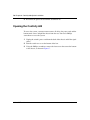
Opening the Contivity 4600
To replace power supplies, replace hard disk drives, or access the diskette drive
for system recovery operations, you must remove the switch’s front bezel.
Note: Removing the front bezel on the Contivity 4600 activates the
chassis intrusion alarm on power only. This intrusion is reported to the
system log file.
The first few times you remove the front bezel it might seem to resist removal.
This is simply because the ball stud and sockets are new. After a few times,
removal is easier. Remove the switch front bezel as follows:
1
Insert a flat-head screwdriver into the slots on the lower left and right sides of
the chassis, and pry the bezel forward.
2
Slide your fingers between the front bezel and the switch.
3
Pull the bezel forward firmly, separating the ball studs on the bezel from the
sockets on the chassis.
Installing Hardware Options for the Contivity VPN Switch
20 Chapter 1 Contivity 4600 Option Installation
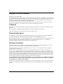
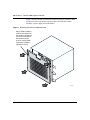
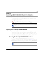
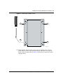
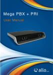
Figure 1 shows you how to remove the front bezel from the Contivity 4600.
You do not need to turn off the switch to remove the front bezel when
installing a power supply or hard disk drive.
Figure 1 Removing the Contivity 4600 front bezel
Using a phillips screwdriver,
rotate screws a quarter turn
anti-clockwise (top right and
left corners), then separate
ball stud on bezel from
socket on chassis (middle
of both sides and bottom
right and left corners)
Bo
ot/
Aler Read
t/F
y
ail
Co
n ti
v it
y4
60
0
CS460005A
302283-E Rev 00
Chapter 1 Contivity 4600 Option Installation 21
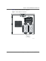
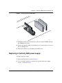
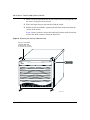
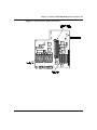
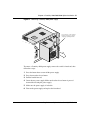
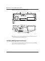
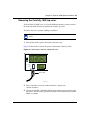
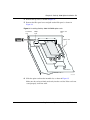
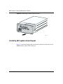
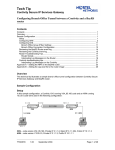
Figure 2 shows the Contivity 4600 front components.
Figure 2 Contivity 4600 front components
Floppy drive
Alert/Fail
Boot/Ready
Disk drives
Power supplies
CS460006A
Installing Hardware Options for the Contivity VPN Switch
22 Chapter 1 Contivity 4600 Option Installation
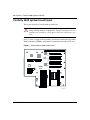
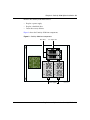
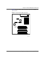
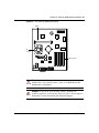
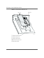
Contivity 4600 system board layout
This section shows the Contivity 4600 system board.
Warning: Only Nortel Networks trained service personnel should
change existing hardware configurations. Improper handling of internal
components or assemblies, with the power connected, could cause severe
injury.
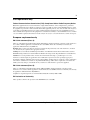
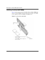
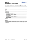
Figure 3 shows a sample Contivity 4600 system board, including the Dual Inline
Memory Modules (DIMMs) and peripheral component interconnect (PCI) slots.
Figure 3 Sample Contivity 4600 system board
1
2
PCI
slots 3
4
5
DIMM
slots
6
CS460007A
302283-E Rev 00
Chapter 1 Contivity 4600 Option Installation 23
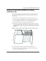
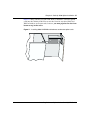
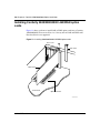
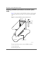
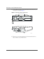
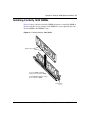
Installing Contivity 4600 LAN/WAN and hardware
accelerator cards
This section describes how you install option cards in the switch option card
slide-out tray. The following procedure is for Nortel Networks trained service
personnel only.
1
Turn off the switch and unplug both power cords from the power source.
2
Unscrew the four slotted thumb-screws securing the slide-out tray. Pull out
the tray by gripping it with the screws. It will only pull out halfway.
3
Remove the filler panel screw and pull out the slot filler panel.
4
Slide the option card into the intended slot. Make sure the card seats firmly
and evenly in the card slot. If the card is not seated properly, it will not work.
Populate the slots from Slot 1 to Slot 6 (top to bottom), in that order, as shown
in Figure 4.
Figure 4 Installing Contivity 4600 LAN/WAN and hardware accelerator cards
CS460014A
5
Secure the option card in the tray with the slot filler panel screw.
6
Push in the tray by gripping it with the screws. Tighten the four slotted
thumb-screws securing the slide-out tray.
Installing Hardware Options for the Contivity VPN Switch
24 Chapter 1 Contivity 4600 Option Installation
7 Plug in both power cords to the power source and turn on the switch.
Caution: Be careful when inserting option cards into the Contivity
4600, because the slide-out tray is not fully supported once pulled out.
You should support the back of the tray with your hand while inserting
an option card.
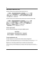
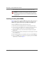
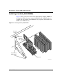
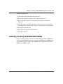
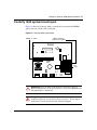
Installing Contivity 4600 DIMMs
Figure 6 shows you how to unlock a DIMM in the Contivity 4600, and remove or
install a DIMM. Install a DIMM in the next available slot (for example, if the
DIMM #1 slot is populated, then add the next DIMM to the DIMM #2 slot).
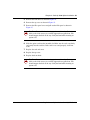
To install a DIMM in the Contivity 4600, follow these steps:
1
Turn off the switch and unplug both power cords from the power source.
2
Unscrew the four slotted thumb-screws securing the slide-out tray. Pull out
the tray by gripping it with the screws. It will only pull out halfway.
3
Unscrew the slide-out tray at the back of the unit and pull it out using the
thumb screws.
4
Remove the support bracket by loosening the two secured captive screws and
the rear Phillips screw.
5
Press down the locking levers on both sides of the next available DIMM slot.
6
Place a new DIMM in the slot, making sure to properly position the DIMM's
alignment keys, as shown in Figure 5.
302283-E Rev 00
Chapter 1 Contivity 4600 Option Installation 25
Figure 5 Installing Contivity 4600 DIMMs
Alignment
Keys
2 1
3 2
4
Locking lever
CS460009A
7
Pull up the locking levers on both sides of the next available DIMM, and snap
the DIMM into its socket.
8
Replace the support bracket by tightening the two secured captive screws and
the rear Phillips screw.
9
Push in the slide-out tray and tighten the thumb-screws.
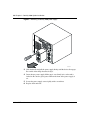
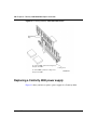
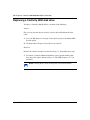
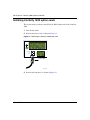
Replacing a Contivity 4600 power supply
To remove the power supply:
1
Remove the front bezel as shown in Figure 1.
2
Use a flat-head screwdriver to unscrew the top and bottom power supply
screws, as shown in Figure 6.
Installing Hardware Options for the Contivity VPN Switch
26 Chapter 1 Contivity 4600 Option Installation
Figure 6 Removing a Contivity 4600 power supply
Bo
ot/
Ale Read
rt/F
y
ail
CS460010A
3
Grab the handle and pull the power supply firmly, until the device disengages.
Be careful of the sharp sheet-metal edges.
4
Insert the new power supply. Make sure it seats firmly in its socket and is
locked in. Be sure the green power LED on the front of the power supply is
on.
5
Secure the power supply screws tightly with a screwdriver.
6
Replace the front bezel.
302283-E Rev 00
Chapter 1 Contivity 4600 Option Installation 27
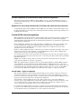
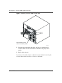
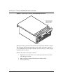
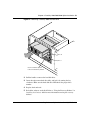
Replacing a Contivity 4600 hard disk drive
Figure 7 shows you how to replace Contivity 4600 hard disk drives for the switch.
Caution: Hard disks are not hot-swappable.
To replace a hard disk drive, you must do the following:
Software
First save any data that has not yet been saved to the hard disk from the disk
cache:
1
Use your Web browser to navigate to the switch, and go to the Admin!File
System display.
2
Click the button “Prepare selected device for removal.”
Hardware
Next, remove the switch’s front bezel as shown in Figure 1, and then follow these
steps:
1
Insert and turn the hard disk drive key to the right. The LED becomes a “U”
for unlocked.
Note: Turning the key shuts off the power to the hard disk drive.
2
Pull the handle to remove the hard disk drive, as shown in Figure 7.
Installing Hardware Options for the Contivity VPN Switch
28 Chapter 1 Contivity 4600 Option Installation
Figure 7 Removing a Contivity 4600 hard disk drive
Bo
ot/
Ale Read
rt/F
y
ail
Drive 0
Drive 1
Insert and turn key, then
remove hard disk by handle.
CS460011A
3
Insert the replacement hard drive fully, and lock it by turning the key
clockwise. Make sure the hard disk drive LED shows the proper drive
number.
4
Replace the front bezel.
If you need to reload the software on the disk, see the information on using the
recovery diskette in the Installing the Contivity 4600 book.
302283-E Rev 00
Chapter 1 Contivity 4600 Option Installation 29
Software
Enable the switch by following these steps:
1
Use your Web browser to navigate to the switch, and go to the Admin!File
System display.
2
Click on the drive and click the Enable button.
Installing Hardware Options for the Contivity VPN Switch
30 Chapter 1 Contivity 4600 Option Installation
302283-E Rev 00
31
Chapter 2
Contivity 4500 Option Installation
This section describes how to install or replace hardware components for the
Contivity 4500.
Warning: Wear an antistatic band when handling electronic
components for the Contivity switch to avoid damaging them.
Note: Turn off the Contivity switch and unplug it before installing LAN
or WAN cards, or system memory.
Opening the Contivity 4500
To replace power supplies, replace hard disk drives, or access the Contivity 4500’s
diskette drive for system recovery operations, you must remove the switch’s front
bezel. To install LAN or WAN cards, or install additional memory, you must
remove the front bezel and then remove the switch’s top cover as well.
Removing the Contivity 4500 front bezel
Note: Removing the front bezel on the Contivity 4500 system activates
the chassis intrusion alarm only if the switch is turned on. This intrusion
is reported to the system log file.
The first few times you remove the front bezel it will be somewhat difficult to
remove. This is because the ball stud and sockets are new. After a few times,
removal is easier. Remove the switch’s front bezel as follows:
Installing Hardware Options for the Contivity VPN Switch
32 Chapter 2 Contivity 4500 Option Installation
1
Insert a flat-head screwdriver into the slots on the lower left and right sides of
the chassis, and pry the bezel forward.
2
Slide your fingers between the front bezel and the switch.
3
Pull the bezel forward firmly, separating the ball studs on the bezel from the
sockets on the chassis.
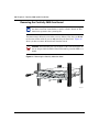
Figure 8 shows you how to remove the front bezel from the switch. You do not
need to turn off the switch to remove the front bezel.
Figure 8 Removing the Contivity 4500 front bezel
Using a screwdriver
seperate ball stud
on bezel from socket
on chassis (4 corners)
CONTIVITY Extranet Switch 45000
CS450011A
302283-E Rev 00
Chapter 2 Contivity 4500 Option Installation 33
Remove the Contivity 4500 front bezel to:
•
•
•
Replace a power supply.
Replace a hard disk drive.
Insert the recovery diskette.
Figure 9 shows the Contivity 4500 front components.
Figure 9 Contivity 4500 front components
Disk drives
3.5" floppy drive
Power supplies
CS450012A
Installing Hardware Options for the Contivity VPN Switch
34 Chapter 2 Contivity 4500 Option Installation
Contivity 4500 system board layout
This section describes installing option cards onto the system board.
Warning: Only Nortel Networks trained service personnel should
change existing hardware configurations. Improper handling of internal
components or assemblies, with the power connected, could cause severe
injury.
Note: Wear an antistatic band when handling electronic components for
the switch to avoid damaging them.
Warning: Turn off the switch and unplug both power cords before
installing LAN and WAN cards or system memory.
302283-E Rev 00
Chapter 2 Contivity 4500 Option Installation 35
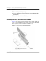
Figure 10 shows the Contivity 4500 system board, in particular the DIMMs and
option card slots.
Figure 10 Sample Contivity 4500 system board
PCI
slots
6
5
4
3
2
1
4
DIMM 3
slots 2
1
CS450013A
Installing Hardware Options for the Contivity VPN Switch
36 Chapter 2 Contivity 4500 Option Installation
Installing Contivity 4500 LAN/WAN and hardware
accelerator option cards
This section describes how you install option cards into the Contivity 4500 option
card slide-out tray. The following procedure is for Nortel Networks trained service
personnel only.
1
Turn off the switch and unplug both power cords from the power source.
2
Unscrew the four slotted thumb screws securing the slide-out tray. Pull out the
tray by gripping it with the screws. It will only pull out half way.
3
Remove the filler panel screw and pull out the slot filler panel.
4
Slide the option card into the intended slot. Make sure the card seats firmly
and evenly into the card slot. If the card is not seated properly, it will not
work. Populate the slots from Slot 1 to Slot 6, in that order.
5
Secure the option card in the tray with the slot filler panel screw.
6
Push in the tray by gripping it with the screws. Tighten the four slotted thumb
screws securing the slide-out tray.
7 Plug in both power cords to the power source and turn on the switch.
Caution: Be careful when inserting option cards into the Contivity
4500, because the slide-out tray is not fully supported once pulled out.
You should support the back of the tray with your hand while inserting
an option card.
302283-E Rev 00
Chapter 2 Contivity 4500 Option Installation 37
Figure 11 shows you how to install LAN, WAN, or hardware accelerator option
cards into the Contivity 4500. You can use the 6 slots for any mix of LAN and
WAN or hardware accelerator cards; however, you must populate the slots from
bottom to top, in that order.
Figure 11 Installing 4500 LAN/WAN and hardware accelerator option cards
Installing Hardware Options for the Contivity VPN Switch
38 Chapter 2 Contivity 4500 Option Installation
Installing Contivity 4500 DIMMs
Figure 12 shows you how to unlock a Dual Inline Memory Module (DIMM) in
the Contivity 4500, and remove or install a DIMM. Install a DIMM in the next
available slot (for example, if the DIMM #1 slot is populated, then add the next
DIMM to the DIMM #2 slot).
Figure 12 Installing Contivity 4500 DIMMs
Rear panel
of switch
Rear
Phillips screw
Alignment
keys
Support bracket
captive screws
4
3
2
1
Locking lever
CS450015A
302283-E Rev 00
Chapter 2 Contivity 4500 Option Installation 39
To install a DIMM into the Contivity 4500, follow these steps:
1
Turn off the switch.
2
Remove the power cords.
3
Unscrew the slide-out tray at the back of the unit and pull it out using the
thumb screws.
4
Remove the support bracket by loosening the two secured captive screws and
the rear Phillips screw.
5
Press down the locking levers on both sides of the next available DIMM slot
to allow the new DIMM to be inserted.
6
Place the new DIMM in the slot, making sure to properly position the
DIMM's alignment keys. Make sure the DIMM is pressed firmly into the
socket.
7
Pull up the locking levers on both sides of the DIMM, and snap the DIMM
into the socket.
8
Replace the support bracket by tightening the two secured captive screws and
the rear Phillips screw.
9
Push in the slide-out tray and tighten the thumb screws.
Caution: Be careful when inserting option cards into the Contivity
4500, because the slide-out tray is not fully supported once pulled out.
You should support the back of the tray with your hand while inserting
an option card.
Installing Hardware Options for the Contivity VPN Switch
40 Chapter 2 Contivity 4500 Option Installation
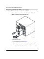
Replacing a Contivity 4500 power supply
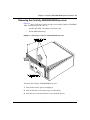
Figure 13 shows you how to replace a hot-swappable power supply for the
Contivity 4500.
Figure 13 Removing a Contivity 4500 power supply
Bo
ot/
Ale Read
rt/F
y
ail
CS460010A
To remove the power supply:
1
Remove the front bezel as shown in Figure 8.
2
Use a flat-head screwdriver to unscrew the top and bottom power supply
screws.
3
Grab the handle and pull the power supply firmly, until the device disengages.
Avoid the sharp sheet-metal edges.
302283-E Rev 00
Chapter 2 Contivity 4500 Option Installation 41
4
Insert the new power supply. Make sure the power supply seats firmly in its
socket and is locked in. Be sure the green power LED on the front of the
power supply is on.
5
Secure the power supply screws tightly with a screwdriver.
6
Replace the front bezel.
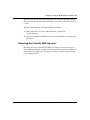
Replacing a Contivity 4500 hard disk drive
Warning: Contivity 4500 hard disks are not hot-swappable.
When swapping a disk drive, you must first perform the steps listed below to
ready the switch for the swap. This process is referred to as “warm-swapping” a
disk drive.
Software
First save any data that has not yet been saved to the hard disk from the disk
cache:
1
Launch a Web browser to the switch, and go to the Admin!File System
display.
2
Click the button “Prepare selected device for removal.”
Hardware
Remove the switch’s front bezel as shown in Figure 8, and then follow these steps:
1
Insert and turn the hard disk drive key to the right. The LED becomes a “U”
for unlocked.
NOTE: Turning the key shuts off the power to the hard disk drive.
2
Pull the handle to remove the hard disk drive as shown in Figure 14.
Installing Hardware Options for the Contivity VPN Switch
42 Chapter 2 Contivity 4500 Option Installation
Figure 14 Removing a Contivity 4500 hard disk drive
Bo
ot/
Ale Read
rt/F
y
ail
Drive 0
Drive 1
Insert and turn key, then
remove hard disk by handle.
CS460011A
3
Insert the replacement hard drive fully, and lock it by turning the key
clockwise. Make sure the hard disk drive LED shows the proper drive
number.
4
Replace the front bezel.
5
Reload the software on the disk. Refer to “Using the Recovery Diskette” in
Installing the Contivity 4600 for more information on using the recovery
diskette.
Software
Enable the switch by following these steps:
1
Use your Web browser to navigate to the switch, and go to the Admin!File
System display.
2
Click on the drive and click the Enable button.
302283-E Rev 00
43
Chapter 3
Contivity 2500/2000/4000 Option Installation
This section describes how to install or replace hardware components for the
Contivity 2500, 2000, and 4000.
Warning: Wear an antistatic band when handling electronic
components for the Contivity switch to avoid damaging them.
Note: Turn off the Contivity switch and unplug it before installing LAN
or WAN cards, or system memory.
Opening the Contivity 2500/2000/4000
To install LAN or WAN cards, install hardware accelerator PCI cards, install
additional memory, replace power supplies, or replace hard disk drives, you must
remove the front bezel and then remove the switch’s top cover. You may find it
easier to work on the system when it has been removed from the rack.
Removing the Contivity 2500/2000/4000 front bezel
To access the Contivity 2500/2000/4000 disk drive for system recovery
operations, you must first remove the switch’s front bezel. Figure 15 shows you
how to remove the front bezel and top cover from the Contivity 2500/2000/4000.
Note: You do not need to turn off the switch to remove the front bezel.
Installing Hardware Options for the Contivity VPN Switch
44 Chapter 3 Contivity 2500/2000/4000 Option Installation
Figure 15 Removing the Contivity 2500/2000/4000 front bezel
Slide fingers behind
front bezel and firm ly
pull forward in the
direction of arrows.
Front Bezel
The first few times you remove the front bezel it will be rather difficult to remove.
This is because the ball stud and sockets are new. After a few times, removal is
easier. Sliding the top cover back is optional; it allows you to get a better grip on
the front bezel for removal.
Remove the switch’s front bezel as follows:
1. Optionally, remove the three screws at the top rear of the chassis, then
slide the top cover back.
2. Slide your fingers between the front bezel and the switch.
3. Pull forward firmly.
302283-E Rev 00
Chapter 3 Contivity 2500/2000/4000 Option Installation 45
Removing the Contivity 2500/2000/4000 top cover
Figure 16 shows you how to remove the top cover from the Contivity 2500/2000/
4000. You must remove the cover to:
•
Install LAN, WAN, or hardware accelerator cards
•
Install additional memory
Figure 16 Removing the Contivity 2500/2000/4000 top cover
To remove the Contivity 2500/2000/4000 top cover:
1
Turn off the switch's power and unplug it.
2
Remove the three screws at the top rear of the chassis.
3
Slide the top cover back and move it away from the chassis.
Installing Hardware Options for the Contivity VPN Switch
46 Chapter 3 Contivity 2500/2000/4000 Option Installation
Contivity 2500/2000/4000 system board layout
Figure 17 shows the Contivity 2500/200 system board, in particular the DIMMs,
option card slots, and the CPU cooling fan. The Contivity 4000 system board is
similar, but has two CPUs as shown in Figure 18.
Figure 17 Sample Contivity 2500/2000 system board
F actory insta lled
D IM M s (1 - 4 )
DIMM
slots
4321
CPU
co olin g fan s
1
Fo ur op tio n ca rd slots
(on ly th re e a re usa ble )
302283-E Rev 00
2 3 4
PCI
slots
Chapter 3 Contivity 2500/2000/4000 Option Installation 47
Figure 18 Sample Contivity 4000 system board
Installing Hardware Options for the Contivity VPN Switch
48 Chapter 3 Contivity 2500/2000/4000 Option Installation
Installing Contivity 2500/2000/4000 LAN/WAN option
cards
Figure 19 shows you how to install LAN or WAN option cards into a Contivity
2500/2000/4000. You can use Slots 1 to 3 for any mix of LAN and WAN cards.
Note that Slot 4 is not supported.
Figure 19 Installing 2500/2000/4000 LAN/WAN option cards
Rear of Unit
Filler Panel
Option Card
Motherboard
Option Card Slots
CS2600017A
302283-E Rev 00
Chapter 3 Contivity 2500/2000/4000 Option Installation 49
To install an option card:
1
Turn off the switch and remove the power cord.
2
Remove the front bezel and top cover as shown in Figure 16.
3
Remove the filler panel screw and pull out the filler panel as shown in
Figure 19.
4
Slide the option card into the intended slot. Make sure the card seats firmly
and evenly in the card slot. If the card is not seated properly, it will not work.
5
Replace the card and screw.
6
Replace the and top cover and front bezel.
7
Turn the switch on.
Installing Contivity 2500/2000/4000 DIMMs
Figure 20 shows you how to unlock a Dual Inline Memory Module (DIMM) in a
Contivity 2500/2000/4000, and remove or install a DIMM. Install a DIMM in the
next available slot (for example, if the DIMM #1 slot is populated, add the next
DIMM to the DIMM #2 slot).
Installing Hardware Options for the Contivity VPN Switch
50 Chapter 3 Contivity 2500/2000/4000 Option Installation
Figure 20 Installing Contivity 2500/2000/4000 DIMMs
Alignment
keys
To remove DIMMs, pull back locking lever
and pull out DIMM.
To install DIMMs, pull back locking levers
and push in DIMM
Locking lever
CS260019A
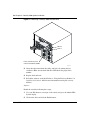
Replacing a Contivity 4000 power supply
Figure 21 shows you how to replace a power supply for a Contivity 4000.
302283-E Rev 00
Chapter 3 Contivity 2500/2000/4000 Option Installation 51
Figure 21 Removing a Contivity 4000 power supply
P re s s d o w n o n th e re le a s e
b u tto n a n d re m o ve p o w e r
su p p ly b y p u llin g h a n d le .
To remove a Contivity 4000 power supply, remove the switch’s front bezel, then
follow these steps:
1
Press the button down to turn off the power supply.
2
Press down on the release button.
3
Pull the handle forward.
4
Insert the new power supply. Make sure that the release button is pressed
down while inserting the power supply.
5
Make sure the power supply is locked in.
6
Turn on the power supply and replace the front bezel.
Installing Hardware Options for the Contivity VPN Switch
52 Chapter 3 Contivity 2500/2000/4000 Option Installation
Replacing a Contivity 4000 disk drive
To replace a Contivity 4000 disk drive, you must do the following:
Software
First save any data that has not yet been saved to the hard disk from the disk
cache:
1
Use your Web browser to navigate to the switch, and go to the Admin!File
System display.
2
Click the button “Prepare selected device for removal.”
Hardware
Remove the switch’s front bezel as shown in Figure 15; then follow these steps:
1
To remove a Contivity 4000 hard disk drive, insert and turn the hard disk
drive key to the right as shown in Figure 22. The LED becomes a “U” for
unlocked.
NOTE: Turning the key shuts off the power to the hard disk drive.
302283-E Rev 00
Chapter 3 Contivity 2500/2000/4000 Option Installation 53
Figure 22 Removing a Contivity 4000 hard disk drive
D rive 0
D rive 1
In sert an d tu rn ke y, th en
re m ove ha rd disk by h an dle.
2
Pull the handle to remove the hard disk drive.
3
Insert the replacement hard drive fully, and lock it by turning the key
clockwise. Make sure the hard disk drive LED shows the proper drive
number.
4
Replace the front bezel.
5
Reload the software on the disk. Refer to “Using the Recovery Diskette” in
Installing the Contivity 4600 for more information on using the recovery
diskette.
Installing Hardware Options for the Contivity VPN Switch
54 Chapter 3 Contivity 2500/2000/4000 Option Installation
Software
Enable the switch by following these steps:
1
Use your Web browser to navigate to the switch, and go to the Admin!File
System display.
2
Click on the drive and click the Enable button.
Installing Contivity 2500/2000/4000 DIMMs
Figure 23 shows you how to unlock a Dual Inline Memory Module (DIMM) and
remove or install the DIMM in the next available slot (for example, if the DIMM
#1 slot is populated, add the next DIMM to the DIMM #2 slot).
Figure 23 Installing Contivity 2500/2000/4000 DIMMs
Alignment
keys
To remove DIMMs, pull back locking lever
and pull out DIMM.
To install DIMMs, pull back locking levers
and push in DIMM
302283-E Rev 00
Locking lever
CS260019A
Chapter 3 Contivity 2500/2000/4000 Option Installation 55
To replace or change a DIMM, follow these steps.
1
Turn off the switch.
2
Remove the power cord.
3
Remove the front bezel as shown in Figure 15.
4
Remove the top cover as shown in Figure 16.
5
Press down the locking levers on both sides of the next available slot to allow
the new DIMM to be inserted.
6
Pull the DIMM up to remove it from the slot.
7
Place a new DIMM in the slot, making sure to properly position the DIMM's
alignment keys. Make sure the DIMM is pressed firmly into the socket.
8
Pull up the locking levers on both sides of the DIMM, and snap the DIMM
into the slot.
9
Replace the top cover.
10 Replace the front bezel.
Memory option
The Contivity 2500/2000/4000 ships with 128 Mbits of memory installed. An
additional 128 Mbits can be installed. To increase the memory, contact Nortel
Networks Customer Support.
Installing Hardware Options for the Contivity VPN Switch
56 Chapter 3 Contivity 2500/2000/4000 Option Installation
302283-E Rev 00
57
Chapter 4
Contivity 2600 Option Installation
This section describes how to install or replace hardware components for the
Contivity 2600.
Warning: Wear an antistatic band when handling electronic
components for the Contivity switch to avoid damaging them.
Note: Turn off the Contivity switch and unplug it before installing LAN
or WAN cards, or system memory.
Opening the Contivity 2600
To access the Contivity 2600 disk drive for system recovery operations, you must
first remove the switch’s front bezel. To install LAN or WAN cards, install
hardware accelerator PCI cards, install additional memory, replace power
supplies, or replace hard disk drives, you must remove the front bezel and then
remove the switch’s top cover. You may find it easier to work on the system when
it has been removed from the rack.
Installing Hardware Options for the Contivity VPN Switch
58 Chapter 4 Contivity 2600 Option Installation
Removing the Contivity 2600 front bezel
Note: Removing the front bezel on the Contivity 2600 system activates
the chassis intrusion alarm whether or not the switch is turned on. This
intrusion is reported to the system log file.
You must remove the bezel to insert the recovery diskette. Note that you do not
need to turn off the switch if you are only removing the front bezel. Figure 24
shows you how to remove the front bezel from the switch.
Caution: When handling the switch outside of the rack-mount shelf, do
not use the part labeled with the Nortel Networks logo and the LEDs as a
handle.
Figure 24 Removing the Contivity 2600 front bezel
CS260015A
302283-E Rev 00
Chapter 4 Contivity 2600 Option Installation 59
The first few times you remove the front bezel it will be rather difficult to remove.
This is because the ball studs and socket clips are new. After a few times, removal
is easier.
To remove the front bezel, you need a Phillips screwdriver.
1
Turn each of the two screws on the front bezel a quarter turn
counter-clockwise.
2
Grip the two handles and pull the bezel towards you firmly to unsnap it from
the chassis.
Removing the Contivity 2600 top cover
To remove the cover to install LAN, WAN, or hardware accelerator cards or to
install additional memory, you must remove the switch’s front bezel and then you
must remove the switch’s top cover. Figure 25 shows you how to remove the top
cover from the switch.
Installing Hardware Options for the Contivity VPN Switch
60 Chapter 4 Contivity 2600 Option Installation
Figure 25 Removing the Contivity 2600 top cover
Remove these four screws
Boot/Ready
Boot/Ready
Alert/Fail
Boot/Ready
Slide cover forward and lift up
CS260006A
➨ Slide the top cover forward approximately 1/4 inch, then lift the lid 2 to 3
inches and move it away from the chassis.
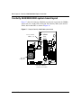
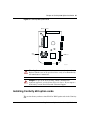
Contivity 2600 system board layout
Figure 26 shows the Contivity 2600’s system board, in particular the DIMMs,
option card slots, and the CPU cooling fan.
302283-E Rev 00
Chapter 4 Contivity 2600 Option Installation 61
Figure 26 The Contivity 2600 system board
DIMMs
1
2
CPU
cooling fan
4 Option card slots
1
2
3
4
CS260008A
Warning: Beware of danger if battery is incorrectly replaced. Replace
with the same or an equivalent battery only, as recommended by the
manufacturer’s instructions.
Danger: In spite of the above warning, which is mandated for
regulatory approval, you should not change the battery. If you suspect a
dead battery, contact Nortel Networks Customer Support.
Installing Hardware Options for the Contivity VPN Switch
62 Chapter 4 Contivity 2600 Option Installation
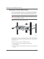
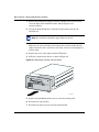
Installing LAN/WAN and hardware accelerator option
cards
Figure 27 shows you how to install LAN, WAN, or hardware accelerator option
cards into the switch. You can use Slots 1 to 4 for any mix of LAN and WAN
cards.
Figure 27 Installing LAN/WAN or hardware accelerator cards
Rear of Unit
Filler Panel
Option Card
Motherboard
Option Card Slots
CS2600017A
To remove the front bezel and cover, you need a Phillips screwdriver.
1
Power off the switch.
2
Remove the power cord.
302283-E Rev 00
Chapter 4 Contivity 2600 Option Installation 63
3
Remove the front bezel as shown in Figure 24.
4
Remove the top cover as shown in Figure 25.
5
Remove the filler panel screw and pull out the filler panel as shown in
Figure 27.
Caution: Be careful when inserting option cards into the Contivity
2600, as the slide-out tray is not fully supported once pulled out. You
should support the back of the tray with your hand while inserting an
option card.
6
Slide the option card into the intended slot. Make sure the card seats firmly
and evenly into the card slot. If the card is not seated properly, it will not
work.
7
Replace the card and screw.
8
Replace the top cover.
9
Replace the front bezel.
Caution: Be careful when inserting option cards into the Contivity
2600, as the slide-out tray is not fully supported once pulled out. You
should support the back of the tray with your hand while inserting an
option card.
Installing Hardware Options for the Contivity VPN Switch
64 Chapter 4 Contivity 2600 Option Installation
Installing Contivity 2600 DIMMs
Figure 28 shows you how to unlock a Dual Inline Memory Module (DIMM) and
remove or install the DIMM in the next available slot (for example, if the DIMM
#1 slot is populated, add the next DIMM to the DIMM #2 slot).
Figure 28 Installing Contivity 2600 DIMMs
Alignment
keys
To remove DIMMs, pull back locking lever
and pull out DIMM.
To install DIMMs, pull back locking levers
and push in DIMM
302283-E Rev 00
Locking lever
CS260019A
Chapter 4 Contivity 2600 Option Installation 65
To replace or change a DIMM, follow these steps.
1
Turn off the switch.
2
Remove the power cord.
3
Remove the front bezel as shown in Figure 24.
4
Remove the top cover as shown in Figure 25.
5
Press down the locking levers on both sides of the next available slot to allow
the new DIMM to be inserted.
6
Pull the DIMM up to remove it from the slot.
7
Place a new DIMM in the slot, making sure to properly position the DIMM's
alignment keys. Make sure the DIMM is pressed firmly into the socket.
8
Pull up the locking levers on both sides of the DIMM, and snap the DIMM
into the slot.
9
Replace the top cover.
10 Replace the front bezel.
Memory option
The Contivity 2600 ships with 128 Mbits of memory installed. An additional 128
Mbits can be installed. To increase the memory, contact Nortel Networks
Customer Support.
Installing Hardware Options for the Contivity VPN Switch
66 Chapter 4 Contivity 2600 Option Installation
302283-E Rev 00
67
Chapter 5
Contivity 1600 Option Installation
This chapter describes how Nortel Networks trained service personnel can change
existing hardware configurations, including installing LAN and WAN cards and
how to add memory for the Contivity 1600.
Warning: Wear an antistatic band when handling electronic
components for the Contivity switch to avoid damaging them.
Note: Turn off the Contivity switch and unplug it before installing LAN
or WAN cards, or system memory.
Opening the Contivity 1600
To access the Contivity 1600’s diskette drive for system recovery operations, you
must first remove the switch’s front bezel. To install LAN or WAN cards, install
hardware accelerator PCI cards, install additional memory, replace power
supplies, or replace hard disk drives, you must remove the front bezel and then
remove the switch’s top cover. You may find it easier to work on the system when
it has been removed from the rack.
Installing Hardware Options for the Contivity VPN Switch
68 Chapter 5 Contivity 1600 Option Installation
Removing the Contivity 1600 front bezel
You must remove the bezel to insert the recovery diskette. Note that you do not
need to turn off the Contivity switch if you are only removing the front bezel.
Figure 29 shows you how to remove the front bezel from the Contivity switch.
Warning: When handling the Contivity switch outside of the
rack-mount shelf, do not use the part labeled with the Nortel Networks
logo and the LEDs as a handle.
Figure 29 Removing the Contivity 1600 front bezel
CS160014A
Note that the first few times you remove the front bezel it will be rather difficult to
remove. This is because the ball studs and socket clips are new. After a few times,
removal is easier.
To remove the front bezel you need a Phillips screwdriver.
1
Turn each of the two screws on the front bezel a quarter turn
counter-clockwise.
2
Grip the two handles and firmly pull the bezel towards you to unsnap it from
the chassis.
302283-E Rev 00
Chapter 5 Contivity 1600 Option Installation 69
Removing the Contivity 1600 top cover
To install LAN or WAN cards, or to install additional memory, you must remove
the Contivity 1600’s front bezel and then the switch’s top cover.
To remove the cover you need a Phillips screwdriver.
Note: You do need to turn off the Contivity switch to remove the top
cover.
1
Turn off the switch’s power and remove the power cord.
Figure 30 shows how to remove the power cord from the Contivity switch.
Figure 30 Removing the Contivity 1600 power cord
100-2240VAC
2-1A
50-60Hz
Power cable
CS160009A
2
Turn each of the two screws on the front bezel a quarter turn
counter-clockwise.
3
Grip the two handles and firmly pull the bezel towards you to unsnap it from
the chassis. Do not use the part labeled with the Nortel Networks logo and the
LEDs as a handle.
Installing Hardware Options for the Contivity VPN Switch
70 Chapter 5 Contivity 1600 Option Installation
4
Use the Phillips screwdriver to remove the four screws that secure the cover
to the chassis, as shown in Figure 31.
Figure 31 Removing the Contivity 1600 top cover
Remove these four screws
Alert/Firm
Boot/Ready
Alert/Fail
Boot/Ready
Slide cover forward and lift up
CS160003A
5
302283-E Rev 00
Slide the top cover forward approximately 1/4 inch, then lift the lid 2 to 3
inches, and move it away from the chassis.
Chapter 5 Contivity 1600 Option Installation 71
Contivity 1600 system board layout
Figure 32 shows the Contivity 1600’s system board, in particular the DIMMs,
option card slots, and the CPU cooling fan.
Figure 32 Contivity 1600 system board
Option card slots
(only two are usable)
DIMMs (1 and 2)
2
1
DIMM
slots
Not
used
1 2
PCI
slots
CS160004A
Warning: Beware of danger if the battery is incorrectly replaced.
Replace with the same or an equivalent battery only, as recommended by
the manufacturer’s instructions.
Danger: In spite of the above warning, which is mandated for
regulatory approval, you should not change the battery. If you suspect a
dead battery, contact Nortel Networks Customer Support.
Installing Hardware Options for the Contivity VPN Switch
72 Chapter 5 Contivity 1600 Option Installation
Installing Contivity 1600 option cards
This section shows you how to install LAN or WAN option cards in the Contivity
1600.
1
Turn off the switch.
2
Remove the power cord, as shown in Figure 33.
Figure 33 Removing the Contivity 1600 power cord
100-2240VAC
2-1A
50-60Hz
Power cable
CS160009A
3
302283-E Rev 00
Remove the front bezel, as shown in Figure 29.
Chapter 5 Contivity 1600 Option Installation 73
4
Remove the top cover, as shown in Figure 31.
5
Remove the filler panel screw and pull out the filler panel, as shown in
Figure 34.
Figure 34 Installing Contivity 1600 LAN/WAN option cards
Screwdriver
slots
Phillips
screw
Option card
slot
Option card
Motherboard
CS160020A
6
Slide the option card into the intended slot, as shown in Figure 35.
Make sure the card seats firmly and evenly into the card slot. If the card is not
seated properly, it will not work.
Installing Hardware Options for the Contivity VPN Switch
74 Chapter 5 Contivity 1600 Option Installation
Figure 35 Installing Contivity 1600 option cards
Option card
Option card
slot
Motherboard
CS160019A
7
Replace the card and screw.
8
Replace the top cover.
9
Replace the front bezel.
10 Reconnect the power cord.
11 Turn on the switch.
302283-E Rev 00
Chapter 5 Contivity 1600 Option Installation 75
Installing Contivity 1600 DIMMs
Figure 36 shows you how to unlock a DIMM and remove or install the DIMM in
the next available slot (for example, if the DIMM # 1 slot is populated, than add
the next DIMM to the DIMM # 2 slot).
Figure 36 Installing Contivity 1600 DIMMs
Alignment keys
To remove DIMMs, pull back
locking levers and pull out DIMM.
To install DIMMs, pull back locking
levers and push in DIMM.
Locking lever
CS160008A
Installing Hardware Options for the Contivity VPN Switch
76 Chapter 5 Contivity 1600 Option Installation
To replace a DIMM, follow these steps.
1
Turn off the switch.
2
Remove the power cord as shown in Figure 30.
3
Remove the front bezel as shown in Figure 29.
4
Remove the top cover as shown in Figure 31.
5
Press down the locking levers on both sides of the DIMM as shown in
Figure 36.
6
Pull the DIMM up to remove it from the slot.
7
Place a new DIMM in the slot, making sure to properly position the DIMM's
alignment keys. Make sure the DIMM is pressed firmly into the socket.
8
Pull up the locking levers on both sides of the DIMM, and snap the DIMM
into the socket.
9
Replace the top cover.
10 Replace the front bezel.
11 Reconnect the power cord.
12 Turn on the switch.
Memory option
The Contivity 1600 ships with 64 Mbits of memory installed. An additional 64
Mbits can be installed. To increase the memory, contact Nortel Networks
Customer Support.
302283-E Rev 00
77
Chapter 6
Contivity 600 Option Installation
This chapter describes how Nortel Networks trained service personnel can change
existing hardware configurations, including installing LAN and WAN cards for
the Contivity 600.
Note: The expansion slot is renamed to Slot 2 by the Contivity 600
software.
Warning: Wear an antistatic band when handling electronic
components for the Contivity 600 to avoid damaging them.
Note: Unplug the power cord from the rear of the Contivity 600 before
installing LAN or WAN interface cards.
To install LAN or WAN cards you must:
1
Remove the power cable.
2
Remove all signal cables.
3
Remove the four screws on the bottom of the switch.
4
Slide the inner chassis out of the casing.
5
Unscrew the PCI interface bracket screw and remove the PCI interface card or
blank PCI bracket.
6
Install a new PCI interface, being careful to completely press the card into the
PCI connector on the mother board.
7
Replace the chassis (along the guide rails) in the outer casing.
8
Replace the bottom screws.
Installing Hardware Options for the Contivity VPN Switch
78 Chapter 6 Contivity 600 Option Installation
9
Reconnect the power cord to turn the switch back on.
Opening the Contivity 600
To access the system, you must remove remove all cables, the power cord, and the
bottom metal screws and pull the chassis from the rear. You need a Phillips
screwdriver to access the system.
1
Unplug the switch’s power cord from the back of the chassis and all the signal
cables.
2
Turn the switch over to see the bottom of the box.
3
Using the Phillips screwdriver, remove the four screws that secure the bottom
to the chassis, as shown in Figure 37.
302283-E Rev 00
Chapter 6 Contivity 600 Option Installation 79
Figure 37 Removing the bottom screws
1
2
3
4
CS60003A
4
Firmly pull the chassis towards you to loosen it from the casing. You can
gently shake it so that it slips outwards and into your hand or you can pull
gently on the I/O expansion bay. Figure 38 shows how to remove the system
from the chassis.
Installing Hardware Options for the Contivity VPN Switch
80 Chapter 6 Contivity 600 Option Installation
Figure 38 Removing the system from the chassis
I/O EXPA
NSION
CONSOL
E
BAY
LAN 1
FD
LAN 0
RC
DC INPU
+12V-1. T
7A
-12V-0.1
A
+5V-10
A
75W MA
X
CS60004A
l
Contivity 600 system board layout
Figure 39 shows the Contivity 600 system board, in particular the option card slot,
DIMM memory, and the CPU cooling fan.
302283-E Rev 00
Chapter 6 Contivity 600 Option Installation 81
Figure 39 Contivity 600 system board
Option card slot
CPU
cooling fan
DIMM slot
CS60005A
Warning: Beware of danger if the battery is incorrectly replaced.
Replace with the same or an equivalent battery only, as recommended by
the manufacturer’s instructions.
Danger: In spite of the above warning, which is mandated for
regulatory approval, you should not change the battery. If you suspect a
dead battery, contact Nortel Networks Customer Support.
Installing Contivity 600 option cards
This section shows you how to install LAN or WAN option cards in the Contivity
600.
Installing Hardware Options for the Contivity VPN Switch
82 Chapter 6 Contivity 600 Option Installation
1
Remove the blank PCI bracket by inserting a Phillips screw driver into the
slot at the right of the blank PCI bracket and rotating the screw
counter-clockwise.
2
Lift out the blank PCI bracket, and slide the replacement card into the
intended slot.
Note: Be careful not to bend the copper fingers in the slot.
Make sure the card seats firmly and evenly in the card slot and that the left
tabbed-end of the card is seated in its slot. If the card is not seated properly, it
will not work.
3
Replace the screw at the right end of the PCI bracket.
4
Slide the system into the chassis as shown in Figure 40.
Figure 40 Replacing the system into the chassis
I/O EXPA
NSION
CONSOL
E
BAY
LAN 1
FD
LAN 0
RC
DC INPU
+12V-1. T
7A
-12V-0.1
A
+5V-10
A
75W MA
X
CS60004A
5
Replace the four Phillips-head screws to secure the bottom panel.
6
Reconnect the signal cables.
7
Reconnect the power cord to restart the Contivity 600.
302283-E Rev 00
Chapter 6 Contivity 600 Option Installation 83
Memory option
The Contivity 600 ships with 64 Mbits of memory installed. No additional
memory can be installed.
Installing Hardware Options for the Contivity VPN Switch
84 Chapter 6 Contivity 600 Option Installation
302283-E Rev 00
85
Index
A
M
acronyms 16
memory
size 55, 65, 76, 83
additional memory
installing 45
antistatic 19, 34
O
option cards slots 22, 35
C
conventions 14
P
conventions, text 14
customer support 17
power supplies 33
replacing a 40
D
power supply
replacing a 50
DIMMs 16, 22, 35
installing 24, 38, 49, 54, 64, 75
documentation map 14
product support 17
publications
hard copy 17
DSU/CSU
required 16
R
F
recovery diskette
drive 33, 58, 68, 78
front bezel
removing 19, 20, 31, 32, 43, 44, 58, 68
S
H
safety 19, 34
power off 37, 39, 48, 55, 62, 65, 72, 76, 81
hard drives 33
L
LAN cards
installing 37, 45, 48, 62, 72, 81
support, Nortel Networks 17
system board
illustration 22, 35
T
technical publications 17
technical support 17
Installing Hardware Options for the Contivity VPN Switch
86 Index
text conventions 14
top cover
removing 45
W
WAN cards
installing 37, 45, 48, 62, 72, 81
302283-E Rev 00