1
Configuring Data
Compression Services
BayRS Version 13.20
Site Manager Software Version 7.20
BCC Version 4.20
Part No. 117352-E Rev 00
March 1999
Bay Networks, Inc.
4401 Great America Parkway
Santa Clara, CA 95054
Copyright © 1998 Bay Networks, Inc.
All rights reserved. Printed in the USA. March 1999.
The information in this document is subject to change without notice. The statements, configurations, technical data,
and recommendations in this document are believed to be accurate and reliable, but are presented without express or
implied warranty. Users must take full responsibility for their applications of any products specified in this document.
The information in this document is proprietary to Bay Networks, Inc.
The software described in this document is furnished under a license agreement and may only be used in accordance
with the terms of that license. A summary of the Software License is included in this document.
Trademarks
AN, BN, FRE, and Bay Networks are registered trademarks and Advanced Remote Node, ARN, ASN, BayRS,
BayStack, System 5000, and the Bay Networks logo are trademarks of Bay Networks, Inc.
All other trademarks and registered trademarks are the property of their respective owners.
Restricted Rights Legend
Use, duplication, or disclosure by the United States Government is subject to restrictions as set forth in subparagraph
(c)(1)(ii) of the Rights in Technical Data and Computer Software clause at DFARS 252.227-7013.
Notwithstanding any other license agreement that may pertain to, or accompany the delivery of, this computer
software, the rights of the United States Government regarding its use, reproduction, and disclosure are as set forth in
the Commercial Computer Software-Restricted Rights clause at FAR 52.227-19.
Statement of Conditions
In the interest of improving internal design, operational function, and/or reliability, Bay Networks, Inc. reserves the
right to make changes to the products described in this document without notice.
Bay Networks, Inc. does not assume any liability that may occur due to the use or application of the product(s) or
circuit layout(s) described herein.
Portions of the code in this software product may be Copyright © 1988, Regents of the University of California. All
rights reserved. Redistribution and use in source and binary forms of such portions are permitted, provided that the
above copyright notice and this paragraph are duplicated in all such forms and that any documentation, advertising
materials, and other materials related to such distribution and use acknowledge that such portions of the software were
developed by the University of California, Berkeley. The name of the University may not be used to endorse or
promote products derived from such portions of the software without specific prior written permission.
SUCH PORTIONS OF THE SOFTWARE ARE PROVIDED “AS IS” AND WITHOUT ANY EXPRESS OR
IMPLIED WARRANTIES, INCLUDING, WITHOUT LIMITATION, THE IMPLIED WARRANTIES OF
MERCHANTABILITY AND FITNESS FOR A PARTICULAR PURPOSE.
In addition, the program and information contained herein are licensed only pursuant to a license agreement that
contains restrictions on use and disclosure (that may incorporate by reference certain limitations and notices imposed
by third parties).
ii
117352-E Rev 00
Bay Networks, Inc. Software License Agreement
NOTICE: Please carefully read this license agreement before copying or using the accompanying software or
installing the hardware unit with pre-enabled software (each of which is referred to as “Software” in this Agreement).
BY COPYING OR USING THE SOFTWARE, YOU ACCEPT ALL OF THE TERMS AND CONDITIONS OF
THIS LICENSE AGREEMENT. THE TERMS EXPRESSED IN THIS AGREEMENT ARE THE ONLY TERMS
UNDER WHICH BAY NETWORKS WILL PERMIT YOU TO USE THE SOFTWARE. If you do not accept these
terms and conditions, return the product, unused and in the original shipping container, within 30 days of purchase to
obtain a credit for the full purchase price.
1. License Grant. Bay Networks, Inc. (“Bay Networks”) grants the end user of the Software (“Licensee”) a personal,
nonexclusive, nontransferable license: a) to use the Software either on a single computer or, if applicable, on a single
authorized device identified by host ID, for which it was originally acquired; b) to copy the Software solely for backup
purposes in support of authorized use of the Software; and c) to use and copy the associated user manual solely in
support of authorized use of the Software by Licensee. This license applies to the Software only and does not extend
to Bay Networks Agent software or other Bay Networks software products. Bay Networks Agent software or other
Bay Networks software products are licensed for use under the terms of the applicable Bay Networks, Inc. Software
License Agreement that accompanies such software and upon payment by the end user of the applicable license fees
for such software.
2. Restrictions on use; reservation of rights. The Software and user manuals are protected under copyright laws.
Bay Networks and/or its licensors retain all title and ownership in both the Software and user manuals, including any
revisions made by Bay Networks or its licensors. The copyright notice must be reproduced and included with any
copy of any portion of the Software or user manuals. Licensee may not modify, translate, decompile, disassemble, use
for any competitive analysis, reverse engineer, distribute, or create derivative works from the Software or user manuals
or any copy, in whole or in part. Except as expressly provided in this Agreement, Licensee may not copy or transfer
the Software or user manuals, in whole or in part. The Software and user manuals embody Bay Networks’ and its
licensors’ confidential and proprietary intellectual property. Licensee shall not sublicense, assign, or otherwise
disclose to any third party the Software, or any information about the operation, design, performance, or
implementation of the Software and user manuals that is confidential to Bay Networks and its licensors; however,
Licensee may grant permission to its consultants, subcontractors, and agents to use the Software at Licensee’s facility,
provided they have agreed to use the Software only in accordance with the terms of this license.
3. Limited warranty. Bay Networks warrants each item of Software, as delivered by Bay Networks and properly
installed and operated on Bay Networks hardware or other equipment it is originally licensed for, to function
substantially as described in its accompanying user manual during its warranty period, which begins on the date
Software is first shipped to Licensee. If any item of Software fails to so function during its warranty period, as the sole
remedy Bay Networks will at its discretion provide a suitable fix, patch, or workaround for the problem that may be
included in a future Software release. Bay Networks further warrants to Licensee that the media on which the
Software is provided will be free from defects in materials and workmanship under normal use for a period of 90 days
from the date Software is first shipped to Licensee. Bay Networks will replace defective media at no charge if it is
returned to Bay Networks during the warranty period along with proof of the date of shipment. This warranty does not
apply if the media has been damaged as a result of accident, misuse, or abuse. The Licensee assumes all responsibility
for selection of the Software to achieve Licensee’s intended results and for the installation, use, and results obtained
from the Software. Bay Networks does not warrant a) that the functions contained in the software will meet the
Licensee’s requirements, b) that the Software will operate in the hardware or software combinations that the Licensee
may select, c) that the operation of the Software will be uninterrupted or error free, or d) that all defects in the
operation of the Software will be corrected. Bay Networks is not obligated to remedy any Software defect that cannot
be reproduced with the latest Software release. These warranties do not apply to the Software if it has been (i) altered,
except by Bay Networks or in accordance with its instructions; (ii) used in conjunction with another vendor’s product,
resulting in the defect; or (iii) damaged by improper environment, abuse, misuse, accident, or negligence. THE
FOREGOING WARRANTIES AND LIMITATIONS ARE EXCLUSIVE REMEDIES AND ARE IN LIEU OF ALL
OTHER WARRANTIES EXPRESS OR IMPLIED, INCLUDING WITHOUT LIMITATION ANY WARRANTY OF
MERCHANTABILITY OR FITNESS FOR A PARTICULAR PURPOSE. Licensee is responsible for the security of
117352-E Rev 00
iii
its own data and information and for maintaining adequate procedures apart from the Software to reconstruct lost or
altered files, data, or programs.
4. Limitation of liability. IN NO EVENT WILL BAY NETWORKS OR ITS LICENSORS BE LIABLE FOR ANY
COST OF SUBSTITUTE PROCUREMENT; SPECIAL, INDIRECT, INCIDENTAL, OR CONSEQUENTIAL
DAMAGES; OR ANY DAMAGES RESULTING FROM INACCURATE OR LOST DATA OR LOSS OF USE OR
PROFITS ARISING OUT OF OR IN CONNECTION WITH THE PERFORMANCE OF THE SOFTWARE, EVEN
IF BAY NETWORKS HAS BEEN ADVISED OF THE POSSIBILITY OF SUCH DAMAGES. IN NO EVENT
SHALL THE LIABILITY OF BAY NETWORKS RELATING TO THE SOFTWARE OR THIS AGREEMENT
EXCEED THE PRICE PAID TO BAY NETWORKS FOR THE SOFTWARE LICENSE.
5. Government Licensees. This provision applies to all Software and documentation acquired directly or indirectly by
or on behalf of the United States Government. The Software and documentation are commercial products, licensed on
the open market at market prices, and were developed entirely at private expense and without the use of any U.S.
Government funds. The license to the U.S. Government is granted only with restricted rights, and use, duplication, or
disclosure by the U.S. Government is subject to the restrictions set forth in subparagraph (c)(1) of the Commercial
Computer Software––Restricted Rights clause of FAR 52.227-19 and the limitations set out in this license for civilian
agencies, and subparagraph (c)(1)(ii) of the Rights in Technical Data and Computer Software clause of DFARS
252.227-7013, for agencies of the Department of Defense or their successors, whichever is applicable.
6. Use of Software in the European Community. This provision applies to all Software acquired for use within the
European Community. If Licensee uses the Software within a country in the European Community, the Software
Directive enacted by the Council of European Communities Directive dated 14 May, 1991, will apply to the
examination of the Software to facilitate interoperability. Licensee agrees to notify Bay Networks of any such
intended examination of the Software and may procure support and assistance from Bay Networks.
7. Term and termination. This license is effective until terminated; however, all of the restrictions with respect to
Bay Networks’ copyright in the Software and user manuals will cease being effective at the date of expiration of the
Bay Networks copyright; those restrictions relating to use and disclosure of Bay Networks’ confidential information
shall continue in effect. Licensee may terminate this license at any time. The license will automatically terminate if
Licensee fails to comply with any of the terms and conditions of the license. Upon termination for any reason,
Licensee will immediately destroy or return to Bay Networks the Software, user manuals, and all copies. Bay
Networks is not liable to Licensee for damages in any form solely by reason of the termination of this license.
8. Export and Re-export. Licensee agrees not to export, directly or indirectly, the Software or related technical data
or information without first obtaining any required export licenses or other governmental approvals. Without limiting
the foregoing, Licensee, on behalf of itself and its subsidiaries and affiliates, agrees that it will not, without first
obtaining all export licenses and approvals required by the U.S. Government: (i) export, re-export, transfer, or divert
any such Software or technical data, or any direct product thereof, to any country to which such exports or re-exports
are restricted or embargoed under United States export control laws and regulations, or to any national or resident of
such restricted or embargoed countries; or (ii) provide the Software or related technical data or information to any
military end user or for any military end use, including the design, development, or production of any chemical,
nuclear, or biological weapons.
9. General. If any provision of this Agreement is held to be invalid or unenforceable by a court of competent
jurisdiction, the remainder of the provisions of this Agreement shall remain in full force and effect. This Agreement
will be governed by the laws of the state of California.
Should you have any questions concerning this Agreement, contact Bay Networks, Inc., 4401 Great America Parkway,
P.O. Box 58185, Santa Clara, California 95054-8185.
LICENSEE ACKNOWLEDGES THAT LICENSEE HAS READ THIS AGREEMENT, UNDERSTANDS IT, AND
AGREES TO BE BOUND BY ITS TERMS AND CONDITIONS. LICENSEE FURTHER AGREES THAT THIS
AGREEMENT IS THE ENTIRE AND EXCLUSIVE AGREEMENT BETWEEN BAY NETWORKS AND
LICENSEE, WHICH SUPERSEDES ALL PRIOR ORAL AND WRITTEN AGREEMENTS AND
COMMUNICATIONS BETWEEN THE PARTIES PERTAINING TO THE SUBJECT MATTER OF THIS
AGREEMENT. NO DIFFERENT OR ADDITIONAL TERMS WILL BE ENFORCEABLE AGAINST BAY
NETWORKS UNLESS BAY NETWORKS GIVES ITS EXPRESS WRITTEN CONSENT, INCLUDING AN
EXPRESS WAIVER OF THE TERMS OF THIS AGREEMENT.
iv
117352-E Rev 00
Contents
Preface
Before You Begin .............................................................................................................xiii
Text Conventions .............................................................................................................xiv
Acronyms ......................................................................................................................... xv
Bay Networks Technical Publications ..............................................................................xvi
How to Get Help .............................................................................................................xvii
Chapter 1
Starting Compression
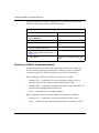
Summary of Bay Networks Data Compression Features ...............................................1-2
Software-Based Data Compression .........................................................................1-2
Hardware-Based Data Compression for the BN Platform ........................................1-3
Previous Hardware-Based Data Compression .........................................................1-4
Preparing a Configuration File for Data Compression ....................................................1-4
Configuring Software Compression ................................................................................1-5
Using the BCC .........................................................................................................1-5
Enabling WCP Compression for PPP ................................................................1-5
Enabling Hi/fn LZS Compression for PPP .........................................................1-7
Enabling WCP Compression for Frame Relay ...................................................1-8
Using Site Manager ................................................................................................1-10
Enabling Compression for PPP .......................................................................1-10
Enabling Compression for Frame Relay ..........................................................1-11
Enabling Compression for X.25 .......................................................................1-12
Configuring Hardware Compression ............................................................................1-13
Configuring Compression for a BN (FRE-2-060E Processor) ................................1-13
Configuring Compression for a BN (Octal Synchronous Link Module) ..................1-14
Configuring Compression for an ASN ....................................................................1-15
For More Information ....................................................................................................1-16
117352-E Rev 00
v
Chapter 2
Data Compression Overview
Bay Networks Compression Services ............................................................................2-2
Data Compression Architecture ......................................................................................2-3
LZ-77 Algorithm .......................................................................................................2-3
Hi/fn LZS Algorithm ..................................................................................................2-4
Compression Control Protocol (CCP) ......................................................................2-4
Bay Networks WAN Compression Protocol (WCP) ..................................................2-4
PPP Hi/fn LZS Compression Protocol ......................................................................2-5
Data Compression Performance ....................................................................................2-5
Hardware Compression ..................................................................................................2-5
Hardware Compression for the BN ..........................................................................2-6
Hardware Compression for the ASN ........................................................................2-6
Hardware Compression Contexts for WCP ..............................................................2-6
Hardware Compression Contexts for Hi/fn LZS .......................................................2-7
How Data Compression Works .......................................................................................2-8
CCP Negotiations ...................................................................................................2-10
WCP Negotiations ..................................................................................................2-10
Data Transmission ..................................................................................................2-11
Compression Features for Specific Protocols ...............................................................2-11
PPP Services .........................................................................................................2-11
PPP Multiline ...................................................................................................2-11
PPP Multilink ...................................................................................................2-12
PPP Dial-on-Demand ......................................................................................2-13
PPP Dial Backup .............................................................................................2-13
Frame Relay Services ............................................................................................2-13
Frame Relay Hybrid Access ............................................................................2-13
Frame Relay Dial-on-Demand .........................................................................2-14
Frame Relay Dial Backup ................................................................................2-14
X.25 Services .........................................................................................................2-15
X.25 PDN and DDN Services ..........................................................................2-15
Adjusting X.25 Max Window Size ....................................................................2-15
vi
117352-E Rev 00
Chapter 3
Customizing Data Compression
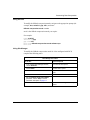
Allocating Compression Memory for WCP .....................................................................3-2
Maximizing the Compression Ratio ..........................................................................3-2
Maximizing Throughput ............................................................................................3-4
8 KB History Size ...............................................................................................3-4
32 KB History Size .............................................................................................3-4
History Size with Hardware Compression .........................................................3-5
Modifying the History Size .................................................................................3-6
Preventing Data Loss for PPP and Frame Relay .....................................................3-8
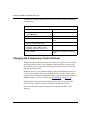
Customizing Hardware Compression .............................................................................3-9
Selecting Software or Hardware Compression ......................................................3-10
Selecting a Fallback Compression Mode ...............................................................3-12
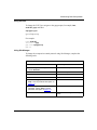
Changing the Compression Control Protocol ...............................................................3-14
Disabling and Reenabling Compression .......................................................................3-16
Disabling and Reenabling WCP .............................................................................3-16
Disabling and Reenabling Hi/fn LZS ......................................................................3-17
Deleting Data Compression from a Router ...................................................................3-18
Appendix A
Site Manager Parameters
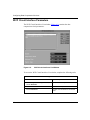
WCP Line Interface Parameters .................................................................................... A-2
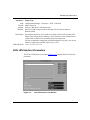
WCP Circuit Interface Parameters ................................................................................. A-8
Hi/fn LZS Interface Parameters ................................................................................... A-11
PPP Interface Parameters for Compression ................................................................ A-14
Appendix B
Monitoring Hardware Compression
Using the BCC show Command
Online Help for show Commands ............................................................................ B-2
show hwcomp all ..................................................................................................... B-2
show hwcomp state ................................................................................................. B-3
show hwcomp stats ................................................................................................. B-4
show hwcomp errors ............................................................................................... B-5
show hwcomp chip .................................................................................................. B-5
show wcp hwcomp all ............................................................................................. B-6
show wcp hwcomp state ......................................................................................... B-7
117352-E Rev 00
vii
show wcp hwcomp stats ......................................................................................... B-8
show wcp hwcomp errors ........................................................................................ B-8
show hifn hwcomp all .............................................................................................. B-9
show hifn hwcomp state ........................................................................................ B-10
show hifn hwcomp stats ........................................................................................ B-11
show hifn hwcomp errors ...................................................................................... B-12
show hardware daughter_card .............................................................................. B-12
Appendix C
Monitoring Software Compression
Using the BCC show Command
Online Help for show Commands ............................................................................ C-2
show wcp lines .............................................................................................................. C-2
show wcp circuits ........................................................................................................... C-3
show wcp vcs ................................................................................................................ C-3
show wcp stats all .......................................................................................................... C-4
show wcp stats error1 .................................................................................................... C-5
show wcp stats error2 .................................................................................................... C-5
show hifn circuits ........................................................................................................... C-6
show hifn stats all .......................................................................................................... C-6
show hifn stats error ...................................................................................................... C-7
Index
viii
117352-E Rev 00
Figures
Figure 2-1.
CCP and WCP Initialization on a PPP Link .............................................2-9
Figure A-1.
WCP Line Interfaces List Window ........................................................... A-2
Figure A-2.
WCP Circuit Interfaces List Window ....................................................... A-8
Figure A-3.
Hi/fn LZS Interface List Window ............................................................ A-11
117352-E Rev 00
ix
Tables
Table 1-1.
Link Modules Supported by FRE-2-060E Processor with Advanced
Compression Coprocessor Daughterboard .............................................1-3
Table 2-1.
Data Compression Algorithms and Protocols ..........................................2-3
Table 3-1.
Memory Allocation for Software Compression History ............................3-4
Table 3-2.
Hardware Compression: 8 KB Contexts ..................................................3-5
Table 3-3.
Hardware Compression: 32 KB Contexts ................................................3-6
Table 3-4.
Default Compression Type Dependencies .............................................3-10
117352-E Rev 00
xi
Preface
Data compression is a routing feature that eliminates redundancy in data streams,
reducing the amount of bandwidth needed to transport LAN protocols over a wide
area. Bay Networks® routers and routing software support data compression over
frame relay, X.25, and PPP (dial-up or leased lines). This guide describes what
you do to start and customize data compression on a Bay Networks router.
You can use the Bay Command Console (BCC™) or Site Manager to configure
data compression on a router. In this guide, you will find instructions for using
both the BCC and Site Manager.
Before You Begin
Before using this guide, you must complete the following procedures. For a new
router:
•
Install the router (see the installation guide that came with your router).
•
Connect the router to the network and create a pilot configuration file (see
Quick-Starting Routers, Configuring BayStack Remote Access, or Connecting
ASN Routers to a Network).
Make sure that you are running the latest version of Bay Networks BayRS™ and
Site Manager software. For information about upgrading BayRS and Site
Manager, see the upgrading guide for your version of BayRS.
117352-E Rev 00
xiii
Configuring Data Compression Services
Text Conventions
This guide uses the following text conventions:
angle brackets (< >)
Indicate that you choose the text to enter based on the
description inside the brackets. Do not type the
brackets when entering the command.
Example: If the command syntax is:
ping <ip_address>, you enter:
ping 192.32.10.12
bold text
Indicates command names and options and text that
you need to enter.
Example: Enter show ip {alerts | routes}.
Example: Use the dinfo command.
italic text
Indicates file and directory names, new terms, book
titles, and variables in command syntax descriptions.
Where a variable is two or more words, the words are
connected by an underscore.
Example: If the command syntax is:
show at <valid_route>
valid_route is one variable and you substitute one value
for it.
screen text
Indicates system output, for example, prompts and
system messages.
Example: Set Bay Networks Trap Monitor Filters
xiv
117352-E Rev 00
Preface
separator ( > )
Shows menu paths.
Example: Protocols > IP identifies the IP option on the
Protocols menu.
vertical line ( | )
Separates choices for command keywords and
arguments. Enter only one of the choices. Do not type
the vertical line when entering the command.
Example: If the command syntax is:
show ip {alerts | routes}, you enter either:
show ip alerts or show ip routes, but not both.
Acronyms
This guide uses the following acronyms:
117352-E Rev 00
ACK
acknowledgement
CCP
Compression Control Protocol
CPC
continuous packet compression
DDN
Defense Data Network
DLCI
data link connection identifier
DTR
data terminal ready
IETF
Internet Engineering Task Force
ILCCP
Individual Link Compression Control Protocol
ILI
intelligent link interface
ISDN
Integrated Services Digital Network
ISDN BRI
ISDN Basic Rate interface
ISDN PRI
ISDN Primary Rate Interface
LAPB
Link Access Procedure-Balanced
LCP
Link Control Protocol
MCE1
multichannel E1
MCT1
multichannel T1
MIB
management information base
xv
Configuring Data Compression Services
NCP
Network Control protocol
PDN
Public Data Network
PPC
packet-by-packet compression
PPP
Point-to-Point Protocol
PVC
permanent virtual circuit
RFC
Request for Comments
VC
virtual circuit
WAN
wide area network
WCP
WAN Compression Protocol
Bay Networks Technical Publications
You can now print Bay Networks technical manuals and release notes free,
directly from the Internet. Go to support.baynetworks.com/library/tpubs/. Find the
Bay Networks product for which you need documentation. Then locate the
specific category and model or version for your hardware or software product.
Using Adobe Acrobat Reader, you can open the manuals and release notes, search
for the sections you need, and print them on most standard printers. You can
download Acrobat Reader free from the Adobe Systems Web site,
www.adobe.com.
You can purchase Bay Networks documentation sets, CDs, and selected technical
publications through the Bay Networks Collateral Catalog. The catalog is located
on the World Wide Web at support.baynetworks.com/catalog.html and is divided
into sections arranged alphabetically:
•
The “CD ROMs” section lists available CDs.
•
The “Guides/Books” section lists books on technical topics.
•
The “Technical Manuals” section lists available printed documentation sets.
Make a note of the part numbers and prices of the items that you want to order.
Use the “Marketing Collateral Catalog description” link to place an order and to
print the order form.
xvi
117352-E Rev 00
Preface
How to Get Help
For product assistance, support contracts, information about educational services,
and the telephone numbers of our global support offices, go to the following URL:
http://www.baynetworks.com/corporate/contacts/
In the United States and Canada, you can dial 800-2LANWAN for assistance.
117352-E Rev 00
xvii
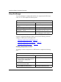
Chapter 1
Starting Compression
The quickest way to begin using data compression on your network is to enable it
with the default configuration that Bay Networks software supplies. This chapter
briefly introduces Bay Networks data compression and includes the procedures
for configuring compression with the default configuration values.
This chapter contains the following information:
117352-E Rev 00
Topic
Page
Summary of Bay Networks Data Compression Features
1-2
Preparing a Configuration File for Data Compression
1-4
Configuring Software Compression
1-5
Configuring Hardware Compression
1-13
For More Information
1-16
1-1
Configuring Data Compression Services
Summary of Bay Networks Data Compression Features
You can configure both software- and hardware-based compression on a circuit or
line basis. Features specific to software and hardware compression follow.
Software-Based Data Compression
Bay Networks offers two software compression protocols:
•
WAN Compression Protocol (WCP) -- for Point-to-Point Protocol (PPP),
frame relay, and X.25 links
•
Hi/fn LZS -- for PPP links only
Note: The Hi/fn™ LZS® compression option is not included with your initial
purchase of BayRS. Bay Networks Hi/fn LZS compression software
incorporates LZS (licensed from Hi/fn) and therefore must be purchased
separately. To run Hi/fn LZS compression on a PPP link between a Bay
Networks router and a non-Bay Networks router, you must obtain a license for
the Hi/fn LZS compression software, which is delivered on a separate CD.
These two protocols use different Lev-Zimpel algorithms to implement
compression and provide different levels of interoperability between Bay
Networks routers and routers made by other vendors.
If both ends of the connection are Bay Networks routers, use WCP as the
compression protocol. If the connection is a PPP link and only one end of the
connection is a Bay Networks router, use Hi/fn LZS.
Software-based data compression works over WAN links. Specifically, WCP
works with PPP, frame relay, and X.25 links; Hi/fn LZS works only with PPP
links. Both WCP and Hi/fn LZS work with PPP multilink. WCP also works with
PPP multiline.
Software compression includes the following features:
1-2
•
Support for all Bay Networks platforms: BayStack™ Access Node (AN®),
Access Stack Node (ASN™), Advanced Remote Node™ (ARN™),
Backbone Node (BN®), and System 5000™
•
Compression for a Bay Networks Fast Routing Engine (FRE ®) module at
4 x 128 KB/s compressed throughput, full duplex; or 512 KB/s aggregate
compressed throughput
117352-E Rev 00
Starting Compression
•
Compression for a BayStack AN platform at 2 x 64 KB/s compressed
throughput, full duplex; or 128 KB/s aggregate compressed throughput
•
Compression on all intelligent link interface (ILI) modules that support serial
and ISDN BRI ports
•
Compression on MCT1 and MCE1 lines
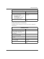
Hardware-Based Data Compression for the BN Platform
The FRE-2-060E processor module with advanced compression coprocessor
daughterboard, available with BayRS Version 12.20 and later for the BN router
platform, extends hardware-based data compression services to the link modules
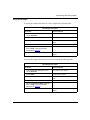
listed in Table 1-1.
Table 1-1.
Link Modules Supported by FRE-2-060E Processor with Advanced
Compression Coprocessor Daughterboard
Link Modules
Bay Networks Part Number
Octal Sync
5008
Oct Sync, HWComp32
AG2104037
Oct Sync, HWComp128
AG2104038
Dual Port Multi Channel T1
5945
Single Port Multi Channel T1
5944
Dual Port Multi Channel E1
77007
Single Port Multi Channel E1
77009
75 ohm Dual Port MCE1-II
AG2111004
75 ohm Single Port MCE1-II
AG2111003
120 ohm Dual Port MCE1-II
AG2111002
120 ohm Single Port MCE1-II
AG2111001
DB15 Quad MCT1
AG2111007
Ethernet Sync Advanced Filter
5431
117352-E Rev 00
1-3
Configuring Data Compression Services
The type of data compression you configure depends on the upper-layer protocol
you want to run over the link, as follows:
•
To run frame relay, use WCP.
•
To run PPP, use WCP if you are connecting Bay Networks routers.
Use Hi/fn LZS if you are connecting routers of different vendors.
Previous Hardware-Based Data Compression
You can continue to use hardware-based data compression services provided by
releases earlier than BayRS Version 12.20, which were based on:
•
Optional daughterboards for PPP and frame relay networks that use the octal
synchronous link module for the BN, using FRE-2 processors only.
Note: If a FRE-2-060E is in the same slot as an octal synchronous hardware
compression daughterboard, the router uses the FRE-2-060E instead of the
octal synchronous daughterboard.
•
Optional net modules for PPP and frame relay networks that use the ASN.
Hardware compression can compress data transmitted over WANs attached to
the following net modules: dual and quad synchronous, MCE1/ISDN PRI,
MCT1/ISDN, dual synchronous with ISDN BRI, and quad BRI.
Preparing a Configuration File for Data Compression
Before starting data compression, you must create and save a configuration file
with at least one unconfigured WAN interface, such as a synchronous or MCT1
port. Refer to the following user guides for instructions on how to start and use the
Bay Networks configuration tool of your choice.
Configuration Tool
User Guide
Bay Command Console (BCC)
Using the Bay Command Console (BCC)
Site Manager
Configuring and Managing Routers with
Site Manager
These guides also describe generically how to create and modify a device
configuration.
1-4
117352-E Rev 00
Starting Compression
Configuring Software Compression
Software compression works on all router platforms and all serial interfaces. After
you open a configuration file, you can enable compression using either the BCC
or Site Manager.
Using the BCC
To configure software compression using the BCC, proceed to the following
sections:
•
Enabling WCP Compression for PPP on page 1-5
•
Enabling Hi/fn LZS Compression for PPP on page 1-7
•
Enabling Compression for Frame Relay on page 1-11
Enabling WCP Compression for PPP
This section provides examples of how to add WCP software compression for PPP
services in several different contexts: on a logical line, on a back-up line, on a
demand-circuit.
Adding WCP to PPP over a Logical Line
To add WCP compression for PPP services on a logical line for a BN router,
configure a logical line, navigate to the ppp prompt (for example, box; mct1 2/1;
logical-line to-tampa; ppp), and enter:
wcp
Example:
box# mct1 2/1
mct1/2/1# logical-line to-tampa
logical-line/to-tampa# ppp
ppp/to-tampa# wcp
wcp/to-tampa#
For information on configuring PPP, see Configuring PPP Services.
117352-E Rev 00
1-5
Configuring Data Compression Services
Adding WCP to PPP over a Backup Line
To add WCP compression for PPP services on a backup line for a BN router,
establish the back up line, navigate to the ppp prompt of the primary circuit (for
example, box; serial 2/1; ppp; ip 1.1.1.1/24; cwc; serial 5/1; dial; cwc;
backup-pool 22; backup-line serial/5/1; cwc; serial 2/1; ppp; backup-circuit
pool-id 22 backup-mode initiator ; back), and enter:
wcp
For example:
box# serial 2/1
serial/2/1# ppp
ppp/2/1# ip 1.1.1.1/24
ip/1.1.1.1/255.255.255.0# cwc
box# serial 5/1
serial/5/1# dial
dial/serial/5/1# cwc
box# backup-pool 22
backup-pool/22# backup-line serial/5/1
backup-line/22/serial/5/1# cwc; serial 2/1; ppp
ppp/2/1# backup-circuit pool-id 22 backup-mode initiator
backup-circuit/22/2/1# back
ppp/2/1# wcp
wcp/2/1#
For information on configuring PPP, see Configuring PPP Services. For
information on configuring dial services, see Configuring Dial Services.
Adding WCP to PPP on a Demand Circuit
To add WCP compression for PPP services on a demand circuit, configure the
demand circuit, navigate to the ppp prompt (for example, box; demand-pool 1;
demand-line serial/5/1; back; demand-circuit to-newyork; ppp), and enter:
wcp
For example:
box# demand-pool 1
demand-pool/1# demand-line serial/5/1
demand-line/1/serial/5/1# back
demand-pool/1# demand-circuit to-newyork
demand-circuit/to-newyork# ppp
ppp/to-newyork# wcp
wcp/to-newyork#
1-6
117352-E Rev 00
Starting Compression
For information on configuring PPP, see Configuring PPP Services. For
information on configuring dial services, see Configuring Dial Services.
Enabling Hi/fn LZS Compression for PPP
This section provides examples of how to add Hi/fn LZS software compression
for PPP services in several different contexts: on a logical line, on a backup line,
or on a demand circuit.
Adding Hi/fn LZS to PPP over a Logical Line
To add Hi/fn LZS compression for PPP services over a logical line for a BN
router, configure a logical line, navigate to the ppp prompt (for example, box;
mct1 2/1; logical-line to-boston; ppp), and enter:
hifn
For example:
box# mct1 2/1
mct1/2/1# logical-line to-boston
logical-line/to-boston# ppp
ppp/to-boston# hifn
hifn/to-boston#
For information on configuring PPP, see Configuring PPP Services.
Adding Hi/fn LZS to PPP over a Backup Line
To add Hi/fn LZS compression for PPP services over a backup line for a BN
router, establish a backup line, navigate to the ppp prompt of the primary circuit
(for example, box; serial 2/1; ppp; ip 1.1.1.1/24; cwc; serial/5/1; dial; cwc;
backup-pool 22; backup-line serial/5/1; cwc; serial 2/1; ppp; backup-circuit
pool-id 22 backup-mode initiator; back), and enter:
hifn
For example:
box# serial 2/1
serial/2/1# ppp
ppp/2/1# ip 1.1.1.1/24
ip/1.1.1.1/255.255.255.0# cwc
box# serial 5/1
serial/5/1# dial
117352-E Rev 00
1-7
Configuring Data Compression Services
dial/serial/5/1# cwc
box# backup-pool 22
backup-pool/22# backup-line serial/5/1
backup-line/22/serial/5/1# cwc; serial 2/1; ppp
ppp/2/1# backup-circuit pool-id 22 backup-mode initiator
backup-circuit/22/2/1# back
ppp/2/1# hifn
hifn/2/1#
For information on configuring PPP, see Configuring PPP Services. For
information on configuring dial services, see Configuring Dial Services.
Adding Hi/fn LZS to PPP over a Demand Circuit
To add Hi/fn LZS compression for PPP services over a demand circuit, configure
the demand circuit, navigate to the ppp prompt (for example, box; demand-pool
1; demand-line serial/5/1; back; demand-ciruit to-newyork; ppp), and enter:
hifn
For example:
box# demand-pool 1
demand-pool/1# demand-line serial/5/1
demand-line/1/serial/5/1# back
demand-pool/1# demand-circuit to-newyork
demand-circuit/to-newyork# ppp
ppp/to-newyork# hifn
hifn/to-newyork#
For information on configuring PPP, see Configuring PPP Services. For
information on configuring dial services, see Configuring Dial Services.
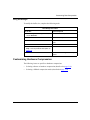
Enabling WCP Compression for Frame Relay
This section provides examples of how to add WCP software compression for
frame relay services for two contexts: for default frame relay service over a BRI
leased line, for nondefault frame relay service over a serial line.
Adding WCP to Default Frame Relay over a BRI Leased Line
To add WCP compression to default frame relay service over a serial line for an
ASN router, navigate to the default-service prompt (for example, stack; bri 3/2/1
mode leased-128k; leased-line/3/2/1/1; frame-relay; default-service/3/2/1/1),
and enter:
1-8
117352-E Rev 00
Starting Compression
wcp
For example:
stack# bri 3/2/1 mode leased-128k
bri/3/2/1# lso
leased-line/3/2/1/1
bri/3/2/1# leased-line/3/2/1/1
leased-line/3/2/1/1# frame-relay
frame-relay/3/2/1/1/# lso
default-service/3/2/1/1 dlcmi/3/2/1/1
frame-relay/3/2/1/1# default-service/3/2/1/1
default-service/3/2/1/1# wcp
wcp/3/2/1/1#
Adding WCP to Nondefault Frame Relay over a Serial Line
To add WCP compression to nondefault frame relay service on a serial line for a
BN router, navigate to the frame relay prompt (for example, box; serial slot 1
connector 2; frame-relay), and enter:
service <service_name>
wcp
service_name is a unique text string that you assign to the service.
For example:
box# serial slot 1 connector 2
serial/1/2# frame-relay
frame-relay/1/2# service to-boston
service/to-boston# wcp
wcp/to-boston#
For information on configuring frame relay, see Configuring Frame Relay
Services.
117352-E Rev 00
1-9
Configuring Data Compression Services
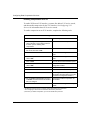
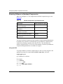
Using Site Manager
To use Site Manager to configure this interface for compression for PPP, frame
relay, or X.25, first complete the following tasks:
Site Manager Procedure
You do this
System responds
1. In the main Site Manager window, choose The Tools menu opens.
Tools.
2. Choose Configuration Manager.
The Configuration Manager menu opens.
3. Choose Local File, Remote File,
Dynamic, or Cache.
Site Manager prompts you for the
configuration file you want to open.
4. Select the file.
The Configuration Manager window
opens, displaying the router modules.
From the Configuration Manager window, proceed to the following sections to
configure a WAN protocol and compression.
•
Enabling Compression for PPP on page 1-10
•
Enabling Compression for Frame Relay on page 1-11
•
Enabling Compression for X.25 on page 1-12
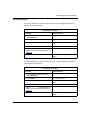
Enabling Compression for PPP
To configure software compression on a PPP interface, complete the following
tasks:
Site Manager Procedure
You do this
System responds
1. In the Configuration Manager window,
click on the link or net module connector
for which you are enabling data
compression.
The Add Circuit window opens.
2. Accept the default circuit name or rename The WAN Protocols window opens.
the circuit; then click on OK.
3. Choose PPP as the WAN protocol.
Site Manager enables the protocol.
(continued)
1-10
117352-E Rev 00
Starting Compression
Site Manager Procedure (continued)
You do this
System responds
4. Click on OK.
The Select Protocols window opens.
5. Enable data compression for PPP by
choosing one of the following:
• Choose WCP if connecting to another
Bay Networks router.
• Choose Hi/fn LZS if connecting
routers of different vendors.
Site Manager enables compression on
this interface.
6. Click on OK.
You return to the Configuration Manager
window.
Enabling Compression for Frame Relay
To configure software compression on a frame relay interface, complete the
following tasks:
Site Manager Procedure
You do this
System responds
1. In the Configuration Manager window,
click on the link or net module connector
for which you are enabling data
compression.
The Add Circuit window opens.
2. Accept the default circuit name or rename The WAN Protocols window opens.
the circuit; then click on OK.
117352-E Rev 00
3. Choose Frame Relay as the WAN
protocol.
Site Manager enables the protocol.
4. Click on OK.
The Select Protocols window opens.
5. Enable data compression for frame relay
by choosing WCP.
Site Manager enables compression on
this interface.
6. Click on OK.
You return to the Configuration Manager
window.
1-11
Configuring Data Compression Services
Enabling Compression for X.25
To enable WCP on an X.25 interface, you must first add an X.25 service record,
and then enable compression for the X.25 interface. See Configuring X.25
Services for information about X.25 service records.
To enable compression on an X.25 interface, complete the following tasks:
Site Manager Procedure
You do this
System responds
1. In the Configuration Manager window,
click on the link or net module connector
for which you are enabling data
compression.
The Add Circuit window opens.
2. Accept the default circuit name or rename The WAN Protocols window opens.
the circuit; then click on OK.
3. Choose X.25 and click on OK.
The X.25 Packet Configuration window
opens.
4. Enter the required information, and then
click on OK.*
The X.25 Service Configuration window
opens.
5. Click on Add.
The X.25 Service Record window opens.
6. Enter the required information, and then
click on OK.*
You return to the X.25 Service
Configuration window.
7. Choose Protocols.
The Protocols menu opens.
8. Choose Add/Delete.
The Select Protocols window opens.
9. Choose WCP.
Site Manager enables compression on
this interface, and then returns you to the
X.25 Service Configuration window.†
10. Set the Enable Compression parameter
to Enable. Do this for each X.25 interface
that you configure.
Site Manager enables compression for
this interface.
11. Click on Done.
You return to the Configuration Manager
window.
* Site Manager requires that you configure certain packet and service parameters.
See Configuring X.25 Services for information about these parameters.
† At the time you enable compression, you can also enable other protocols.
1-12
117352-E Rev 00
Starting Compression
Configuring Hardware Compression
To use hardware compression for the BN router, you must have either an octal
synchronous link module with a hardware compression daughterboard or the
FRE-2-060E processor module with advanced compression coprocessor
daughterboard. For the ASN router, you must have a hardware compression net
module.
You can use hardware compression with PPP and frame relay.
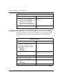
Configuring Compression for a BN (FRE-2-060E Processor)
To configure hardware compression for a BN that has a FRE-2-060E processor
module with advanced compression coprocessor daughterboard, complete the
following tasks:
Site Manager Procedure
You do this
System responds
1. In the Configuration Manager window,
Site Manager selects the module.
click on the slot in which the FRE-2-060E
processor module with advanced
compression coprocessor is installed.
Then choose the link module for which you
want to enable data compression.
2. Click on OK.
You return to the Configuration Manager
window. The link module is added to the
slot.
3. Choose a port.
The Add Circuit window opens.
4. Accept the default circuit name or enter a
new name; then click on OK.
The WAN Protocols window opens.
5. Choose one of these WAN protocols:
• PPP
• Frame Relay
Site Manager selects the protocol.
6. Click on OK.
The Select Protocols window opens.
(continued)
117352-E Rev 00
1-13
Configuring Data Compression Services
Site Manager Procedure (continued)
You do this
System responds
7. Enable data compression as follows:
• For frame relay, choose WCP.
• For PPP, if connecting to another Bay
Networks router, choose WCP.
• For PPP, if connecting routers of
different vendors, choose Hi/fn LZS.
Site Manager enables compression on
this interface.
8. Click on OK.
You return to the Configuration Manager
window.
Configuring Compression for a BN (Octal Synchronous Link Module)
To configure hardware compression for a BN that has an octal synchronous link
module with a hardware compression daughterboard, complete the following
tasks:
Site Manager Procedure
You do this
System responds
1. In the Configuration Manager window,
click on an empty slot and choose one of
the following octal synchronous link
modules with a hardware compression
daughterboard:
• AG2104037
• AG2104038*
Site Manager selects the module.
2. Click on OK.
You return to the Configuration Manager
window. The link module is added to the
slot.
3. Choose a port.
The Add Circuit window opens.
4. Accept the default circuit name or enter a
new name, and then click on OK.
The WAN Protocols window opens.
5. Choose one of these WAN protocols:
• PPP
• Frame Relay
Site Manager selects the protocol.
6. Click on OK.
The Select Protocols window opens.
(continued)
1-14
117352-E Rev 00
Starting Compression
Site Manager Procedure (continued)
You do this
System responds
7. Choose WCP.
Site Manager enables compression on
this interface.
8. Click on OK.
You return to the Configuration Manager
window.
* If you have a hardware compression link module on a BN, you can use hardware compression on
any WAN port on a slot. Hardware compression on the BN does not work across slots.
Configuring Compression for an ASN
To configure hardware compression for the ASN, complete the following tasks:
Site Manager Procedure
You do this
System responds
1. In the Configuration Manager window,
click on an empty slot and choose one of
the following net modules for hardware
compression:
• AF2104007
• AF2104012*
Site Manager selects the net module.
2. Click on OK.
You return to the Configuration Manager
window. The net module is added to the
slot.
3. Click on the slot that contains the
hardware compression module and
choose a WAN net module.
Site Manager selects the WAN net
module.
4. Click on OK.
You return to the Configuration Manager
window. The WAN net module is placed
over the compression module.
5. Choose a port.
The Add Circuit window opens.
6. Accept the default circuit name or enter a
new name; then click on OK.
The WAN Protocols window opens.
7. Choose one of these WAN protocols:
• PPP
• Frame Relay
Site Manager selects the protocol.
(continued)
117352-E Rev 00
1-15
Configuring Data Compression Services
Site Manager Procedure (continued)
You do this
System responds
8. Click on OK.
The Select Protocols window opens.
9. Choose WCP.
Site Manager enables compression on
this interface.
10. Click on OK.
You return to the Configuration Manager
window.
* If you have a hardware compression net module on an ASN, you can use hardware compression on
any WAN port on that single router or slot. Hardware compression on the ASN does not work
across slots; that is, it does not provide compression for any other ASNs in the stack.
For More Information
For detailed information about Bay Networks data compression, see Chapter 2,
“Data Compression Overview.”
For information and recommendations about customizing compression, see
Chapter 3, “Customizing Data Compression.”
1-16
117352-E Rev 00
Chapter 2
Data Compression Overview
Bay Networks data compression services enable you to reduce line costs and
improve response times over wide area networks. In addition, they eliminate
redundancies in data streams. When you use compression on a network,
bandwidth efficiency improves so you can transmit more data.
This chapter contains the following information:
117352-E Rev 00
Topic
Page
Bay Networks Compression Services
2-2
Data Compression Architecture
2-3
Data Compression Performance
2-5
Hardware Compression
2-5
How Data Compression Works
2-8
Compression Features for Specific Protocols
2-11
2-1
Configuring Data Compression Services
Bay Networks Compression Services
Bay Networks compression services include:
•
Software-based compression for PPP, frame relay, and X.25 networks for all
router platforms and all serial interfaces.
PPP compression works on multiline, multilink, on the ISDN BRI and PRI
modules, and on lines that use Raise DTR or V.25bis modem interfaces with
dial services. Frame relay compression works on multiline and dial backup
lines.
•
Hardware-based compression for PPP and frame relay networks for BN
routers using one of the following modules:
-- Octal synchronous link module using FRE-2 processors
-- FRE-2-060E processor module with the advanced compression
coprocessor daughterboard to which you can connect a broad range of
Bay Networks link modules (see “Hardware-Based Data Compression for
the BN Platform” on page 1-3 for the list of supported link modules).
Hardware compression on the BN supports all PPP and frame relay services
that WCP software compression supports.
•
Hardware-based compression for PPP and frame relay networks for the ASN
router.
A compression net module compresses data transmitted over a WAN network
by dual and quad synchronous, MCE1/ISDN PRI, MCT1/ISDN, dual
synchronous with ISDN BRI, and quad BRI net modules. Hardware
compression on the ASN supports all PPP services that WCP software
compression supports.
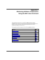
Bay Networks WCP software- and hardware-based compression interoperate fully
because they use the same algorithm.
Hi/fn LZS hardware compression is supported by the FRE-2-060E processor with
the advanced compression coprocessor daughterboard for the BN when
connecting to a router from another vendor that is also running the Hi/fn LZS
algorithm.
To use software data compression effectively, you must decide how to allocate
memory for this task. The goal is to compress data as much as possible and to
transmit the data as quickly as possible without taxing the resources of the router.
2-2
117352-E Rev 00
Data Compression Overview
Data Compression Architecture
WCP and Hi/fn LZS use different compression algorithms and protocols. The
compression protocol that you choose depends on whether you are
communicating with routers from Bay Networks or other vendors.
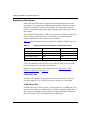
Table 2-1 lists the algorithms and protocols that Bay Networks uses to provide
data compression services for WCP and Hi/fn LZS.
Table 2-1.
Data Compression Algorithms and Protocols
WCP
Hi/fn LZS
LZ-77 algorithm
Hi/fn LZS algorithm
Compression Control Protocol (RFC 1962)
Compression Control Protocol (RFC 1962)
Bay Networks proprietary WAN
Compression Protocol (WCP)
References the PPP Hi/fn LZS
Compression Protocol (RFC 1974) as a
guideline
You must ensure that routers at both ends of the connection are using the same
compression protocol:
•
If both ends of the connection are Bay Networks routers, configure both
routers to use WCP as the compression protocol.
•
If the connection is a PPP link and only one end of the connection is a Bay
Networks router, configure both routers to use Hi/fn LZS.
If you want the router to negotiate which protocol is used, use the BCC or Site
Manager to set the Compression Protocol parameter to Any (see page A-15 for the
parameter description).
LZ-77 Algorithm
Bay Networks WCP data compression software is based on a Lempel-Ziv (LZ-77)
algorithm. The algorithm uses a sliding history buffer that stores the data that the
network link has processed most recently. The compressor compares new data
strings with data it has already processed and stored in the buffer. When the
compressor detects data strings that match data it has already processed, it
replaces those strings with offset and length tokens that are shorter than the
original strings, thus compressing the data.
117352-E Rev 00
2-3
Configuring Data Compression Services
Hi/fn LZS Algorithm
Hi/fn is a wholly owned subsidiary of Stac, Inc. Bay Networks Hi/fn LZS
compression software incorporates LZS from Hi/fn.
Bay Networks Hi/fn LZS compression software is based on the Hi/fn LZS
algorithm to transport compressed packets across a PPP link. Hi/fn LZS
implements an error detection mechanism, which means that it can detect whether
packets are lost during transmission. Hi/fn LZS does not retransmit packets if they
are lost.
The Hi/fn LZS compression algorithm searches incoming data for redundant data
strings and replaces these strings in the outgoing data with encoded tokens of
shorter length. Hi/fn LZS creates the encoded tokens from information in a table
that the Hi/fn LZS algorithm builds. This table consists of string matches, which
point to previous incoming data. As the table is built and tokens are created,
subsequent data is compressed based on previous data.
Compression Control Protocol (CCP)
Bay Networks uses RFC 1962, the Compression Control Protocol (CCP), to
enable or disable compression across a PPP link and determine what kind of
compression is used. CCP also includes a history reset request and
acknowledgment capability, which Hi/fn LZS uses but WCP does not. WCP uses
its own negotiation mechanism.
Bay Networks WAN Compression Protocol (WCP)
Bay Networks proprietary WAN Compression Protocol (WCP) is an IETF draft
standard. WCP enables compression for frame relay and for X.25, and transports
compressed packets for PPP, frame relay, and X.25. WCP negotiates compression
mode, history size, and buffer size. For PPP and frame relay, WCP also
retransmits packets in the event of packet loss and protects against inadvertent
data expansion (LAPB retransmits packets for X.25).
WCP is most effective for sites that have WAN connections operating at relatively
low speeds such as 56/64 KB, where you want to achieve data compression at low
cost and with minimal memory requirements. WCP supports connections up to
512 KB/s on the FRE-040. For networks operating at faster speeds, you should
use hardware compression.
2-4
117352-E Rev 00
Data Compression Overview
PPP Hi/fn LZS Compression Protocol
PPP uses CCP to negotiate how the router uses the Hi/fn LZS Compression
Protocol (RFC 1974). Specifically, CCP negotiates the different compression
modes that RFC 1974 supports. Bay Networks negotiates only mode 3 and the
number of compression histories, of which we support only one history.
RFC 1974 is specified only as an error detection protocol; unlike WCP, it does not
contain a transmit history. Instead, it relies on upper-layer protocols to retransmit
data when errors occur.
For more information about compression protocol modes, refer to RFC 1974.
Data Compression Performance
The goals in using data compression are to achieve a high compression ratio while
maximizing throughput. Compression ratio is the size of uncompressed data
compared to the size of the same data after it is compressed. Throughput refers to
the amount of data that goes across the network in a specific amount of time. The
amount of throughput can indicate the efficiency and speed of the network.
The compression ratio varies according to the effectiveness of the compression
algorithm, but also according to the characteristics of the data you are
transmitting. Data that includes many redundant strings compresses at a high
ratio.
Throughput varies according to the number of devices in the network through
which the data must travel. Throughput is also affected by the compression and
decompression process.
Hardware Compression
Bay Networks hardware-based compression works with frame relay and PPP
networks. It best serves sites that support T1 or E1 lines, which often concentrate
many lower-speed remote connections. The hardware compression facility
operates at high speeds and also supports high-density WAN connections. Use
hardware compression when you want to achieve high compression ratios and
throughput, and also want to conserve router memory for other functions.
117352-E Rev 00
2-5
Configuring Data Compression Services
Hardware Compression for the BN
The BN supports the following compression daughterboards:
•
AG2104037 - Octal Sync with a 32-contexts hardware compression
daughterboard
•
AG2104038 - Octal Sync with a 128-contexts hardware compression
daughterboard
•
Advanced compression coprocessor daughterboard with 128 or 256 contexts
installed on the FRE-2-060E processor module
Hardware Compression for the ASN
The hardware compression net modules for the ASN can compress data
transmitted over WAN networks attached to dual and quad synchronous,
MCE1/ISDN PRI, MCT1/ISDN, dual synchronous with ISDN BRI, and
quad BRI net modules. One compression net module in a single ASN can provide
hardware compression for all the net modules on that router. It does not provide
compression for any other ASN in the stack.
The compression net module is available in both a 32-contexts and a 128-contexts
version.
The ASN supports the following compression net modules:
•
AF2104007 - 32-contexts hardware compression net module
•
AF2104012 - 128-contexts hardware compression net module
Hardware Compression Contexts for WCP
A context refers to compression and decompression for a single virtual
circuit (VC). Compression hardware maps a context to specific regions of
compression and decompression memory:
•
2-6
A 32-contexts compression daughterboard or net module can run compression
simultaneously over 31 continuous packet compression (CPC) contexts, each
using an 8 KB history size, with one shared 8 KB packet-by-packet
compression (PPC) context.
117352-E Rev 00
Data Compression Overview
•
A 128-contexts compression daughterboard or net module can run
compression simultaneously over 127 CPC contexts, each using an 8 KB
history size, with one shared 8 KB PPC context.
•
A 256-contexts advanced compression coprocessor daughterboard installed
on a FRE-2-060E processor module can run compression simultaneously over
255 CPC contexts, each using an 8 KB history size, with one shared
8 KB PPC context.
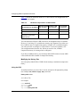
The 32-contexts, 128-contexts, and 256-contexts daughterboards and net modules
differ in their amount of memory:
•
The 32-contexts daughterboard and net module have 512 KB compression/
256 KB decompression.
•
The 128-contexts daughterboards and net module have 2 MB compression/
1 MB decompression.
•
The 256-contexts advanced compression coprocessor daughterboard has
4 MB compression/2 MB decompression.
Note: You should plan your network to use hardware compression on the VCs
most important to you within the limits of your equipment. If you configure
more VCs for hardware compression than your daughterboard or net module
can support, you cannot control which VCs will use hardware compression.
By default, all VCs that exceed the hardware context limit use software
compression.
For information about customizing CPC and PPC, see Chapter 3, “Customizing
Data Compression.”
Hardware Compression Contexts for Hi/fn LZS
Hi/fn LZS supports a 2 KB history size and CPC contexts only. Hi/fn LZS does
not support PPC contexts.
117352-E Rev 00
2-7
Configuring Data Compression Services
How Data Compression Works
To transmit compressed data, the router must complete one or both of the
following:
•
CCP negotiations (for PPP connections using WCP or Hi/fn LZS)
•
WCP negotiations (for PPP, frame relay, and X.25 connections using WCP)
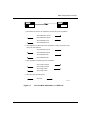
The following sections describe how these negotiations work. As you read these
sections, see Figure 2-1, which illustrates CCP and WCP initialization on a PPP
link.
If compression is across a frame relay or X.25 link, the router negotiates only
WCP; CCP does not apply.
2-8
117352-E Rev 00
Data Compression Overview
Router A
Router B
1. PPP interface on network; LCP negotiations complete; begin CCP negotiations:
Send initialization-request
Send initialization-request
Send initialization-ACK
Send initialization-ACK
2. CCP negotiations complete; begin WCP negotiations, including compression mode,
history size, and buffer size:
Send initialization-request
Send initialization-request
Send initialization-ACK
Send initialization-ACK
3. WCP negotiations complete; begin NCP negotiations:
Send configure-request
Send configure-request
Send configure-ACK
Send configure-ACK
4. NCP open; begin transmitting data:
Send data
DC0001A
Figure 2-1.
117352-E Rev 00
CCP and WCP Initialization on a PPP Link
2-9
Configuring Data Compression Services
CCP Negotiations
CCP allows the two ends of a PPP connection to negotiate whether to use data
compression and, if so, which algorithm to use. Both WCP and Hi/fn LZS use
CCP to negotiate compression.
Note: If one side of a link requests an algorithm that the other side does not
support, traffic over the link continues, but in uncompressed form.
In Figure 2-1, negotiations begin when PPP establishes a link. CCP uses the same
configuration and network control protocol negotiations that the Link Control
Protocol (LCP) uses to establish a link.
For Hi/fn LZS, CCP also provides the following:
•
History reset request messages
•
Request acknowledgment messages
These messages help to synchronize the receipt and transmission of the
compression and decompression history after a packet is lost. WCP does not use
these messages.
For an explanation of LCP negotiations, see Configuring PPP Services.
WCP Negotiations
WCP allows two ends of a PPP, frame relay, or X.25 connection to negotiate
compression.
Frame relay and X.25 use WCP to negotiate whether to use data compression and
which algorithm to use. (PPP uses CCP and WCP to negotiate this information.)
As with PPP, if one side of a link requests an algorithm that the other side does not
support, traffic continues, but in uncompressed form. All three WAN protocols use
WCP to negotiate options such as compression mode, history size, and buffer size.
Each side of a link running data compression has a compressor, a decompressor, a
compression history, and a retransmission buffer. You can edit WCP parameters
for compression mode, history size, and buffer size to optimize compression
performance on your network (see “Allocating Compression Memory for WCP”
on page 3-2).
2-10
117352-E Rev 00
Data Compression Overview
Data Transmission
For PPP links using WCP, Network Control Protocol (NCP) negotiations and
WCP negotiations occur simultaneously. When PPP, NCP, and WCP negotiations
are complete, data transmission using compression begins.
For PPP links using Hi/fn LZS, data transmission using compression begins when
CCP and NCP negotiations are complete.
For frame relay and X.25 links, data transmission using compression begins when
WCP negotiations are complete.
Compression Features for Specific Protocols
Bay Networks data compression services vary in some details according to the
WAN protocols that you configure. Read the following sections to learn about
how Bay Networks implements data compression for PPP, frame relay, and X.25
services.
PPP Services
You can use software or hardware data compression on all PPP circuits, including
multiline and multilink, bandwidth-on-demand, dial-on-demand, and dial backup
lines. When you use compression on a bandwidth-on-demand, dial-on-demand, or
dial backup circuit, WCP automatically configures or deletes compression as lines
are added to or removed from the circuit.
PPP Multiline
Multiline enables you to configure a single circuit consisting of one or more WAN
data paths. A data path is a logical point-to-point channel; it can be a permanent
or dial-up physical line, or it can be a virtual circuit connection. Multiline
provides both increased fault tolerance and greater bandwidth between two sites.
For more information about Bay Networks multiline, see Configuring WAN Line
Services.
117352-E Rev 00
2-11
Configuring Data Compression Services
PPP Multilink
Multilink provides capabilities beyond those of multiline circuits. Multilink
consists of a bundle of lines between two peers, consisting of up to four links.
Multilink allows you to:
•
•
•
•
•
Distribute traffic across the lines in the bundle in amounts roughly
proportional to the effective bandwidth of each link.
Use lines that have different speeds, proportionally distributing traffic over
those lines.
Balance traffic load and restore packet sequence.
Use switched lines (such as ISDN B channels) as well as leased lines.
Monitor traffic volume.
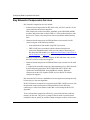
Depending on the version of BayRS, the router handles the operation of PPP
multilink and WCP differently.
For BayRS Version 12.10 and later, by default the router negotiates WCP above
the PPP multilink bundle for new circuits only. Negotiating compression above
the bundle means that data packets are first compressed and then distributed
across the links in the bundle. The distribution of traffic occurs once for the entire
bundle, so the balance of traffic across the bundle is more accurate. In addition,
the router uses less memory for compression.
Routers using BayRS Version 12.10 or later with an older configuration file
negotiate WCP below the multilink bundle by default. Negotiating compression
below the bundle means that data packets are first distributed across the links and
then compressed. Compression is done individually for every link. You can
reconfigure the circuit to negotiate WCP above the bundle. To do so, use the BCC
or Site Manager to change the CCP Type parameter to CCP on the routers at both
ends of the link.
If you configure a new multilink circuit on a local router running BayRS Version
12.10 or later, and the remote router is running a version earlier than 12.10, you
must change the CCP Type parameter from the default (CCP) to ILCCP for the
local router and set the PPP Mode to multilink.
For a description of the CCP Type parameter, see page A-14.
2-12
117352-E Rev 00
Data Compression Overview
PPP Dial-on-Demand
Dial-on-demand service enables you to establish a circuit only when you want to
transmit and receive data, as opposed to having a leased line, which is always
available. By using a circuit on a demand basis, you can significantly reduce your
line costs.
PPP Dial Backup
PPP also allows you to configure dial backup service. If a primary PPP line fails
and you enabled dial backup, the router automatically establishes a backup line.
You cannot enable any protocols, including compression, on a backup circuit,
because a backup circuit inherits its protocols from the primary circuit. If the
primary circuit uses compression, then the backup circuit does also.
For more information about Bay Networks dial services, see Configuring Dial
Services.
Frame Relay Services
You can use software (WCP only) or hardware data compression with frame relay.
You can use compression with some virtual circuits (VCs), and not with others, as
you choose, both for regular frame relay VCs, and for those you configure in
hybrid mode. You can also use compression with dial-on-demand and dial backup
services.
You must enable compression on both sides of a frame relay link. If you enable
data compression on only one side of the link, data transmission occurs, but in
uncompressed form.
Frame Relay Hybrid Access
Hybrid access enables you to combine bridging and routing over a single frame
relay interface.
117352-E Rev 00
2-13
Configuring Data Compression Services
When you enable data compression for frame relay on a hybrid circuit, both the
bridged and the routed traffic over that circuit are compressed. Note that
compression applies only to the hybrid permanent virtual circuit (PVC), and not to
the other PVCs from the main circuit, unless you also enabled compression for
those interfaces. Conversely, if you enable data compression for other PVCs, but
not on a PVC you configured for hybrid mode, the hybrid circuit does not use
compression.
Frame Relay Dial-on-Demand
Frame relay enables you to configure dial-on-demand service. Dial-on-demand
enables the router to activate a dial-up line only when there is data to send or when
you configure the router to force the activation of a dial-up line. Using frame relay
dial-on-demand ensures that you establish connections only when you need them,
as opposed to using leased lines, which are active regardless of data activity. This
helps you reduce line costs.
Frame Relay Dial Backup
Frame relay enables you to configure dial backup service. If a primary frame relay
circuit fails and you enable dial backup, the router automatically establishes a
backup circuit. The backup circuit can be a PPP circuit, a frame relay circuit that
uses direct mode (a service record with only one PVC), or a frame relay circuit
that uses group mode (a service record with two or more PVCs).
The backup circuit can inherit the primary circuit’s configuration, or it can use its
own. When the frame relay primary and backup use the same configuration, they
have a shared configuration. The backup circuit uses the same network layer
address as the primary circuit. The data link layer configuration, that is, the
backup PVCs, data link connection identifiers (DLCIs), and filters, can be the
same or different from the primary.
If the backup uses a unique configuration, it is a secondary configuration. A
secondary configuration uses a different network layer address, PVCs, and filters
from the primary.
To use data compression with frame relay dial backup, you must configure
compression on both the primary and the backup circuit. The backup circuit does
not necessarily inherit the PVC configuration from the primary circuit, because
the backup PVCs can have different configurations from the primary.
2-14
117352-E Rev 00
Data Compression Overview
For more information about Bay Networks dial services, see Configuring Dial
Services.
X.25 Services
An X.25 network permits as many as 128 VCs to exist on the same physical link at
the same time. You can configure each of these interfaces individually to use data
compression or not.
X.25 PDN and DDN Services
When you use data compression on circuits that you configure for X.25 Public
Data Network (PDN) or Defense Department Network (DDN) services, you must
enable compression on both sides of the link. If you configure compression on
only one side of a PDN or DDN link, the data that travels over that link will be
corrupted.
You must also remember to enable the X.25 service record compression parameter
for each X.25 interface that you configure. For more information about this
parameter, see Configuring X.25 Services.
Adjusting X.25 Max Window Size
Window size can affect packet throughput across the X.25 network. Setting the
X.25 Max Window Size parameter too low can cause the router to drop packets
and render data compression ineffective. You should configure this parameter at a
higher value than the default setting, see Configuring X.25 Services.
117352-E Rev 00
2-15
Chapter 3
Customizing Data Compression
When you enable data compression, default values are in effect for all parameters.
This chapter provides information about customizing Bay Networks compression
to use it most effectively on your network.
This chapter contains the following information:
117352-E Rev 00
Topic
Page
Allocating Compression Memory for WCP
3-2
Customizing Hardware Compression
3-9
Changing the Compression Control Protocol
3-14
Disabling and Reenabling Compression
3-16
Deleting Data Compression from a Router
3-18
3-1
Configuring Data Compression Services
Allocating Compression Memory for WCP
Using WCP across a network involves allocating memory to maximize
compression without taxing the resources of your router. To achieve this goal, you
can customize compression parameters to:
•
Maximize the compression ratio.
•
Maximize throughput.
•
Prevent data loss.
Maximizing the Compression Ratio
You can compress data in one of two modes:
•
Continuous packet compression (CPC) maintains compression history across
packets. CPC yields a higher compression ratio than packet-by-packet
compression. In most circumstances, you should select CPC, the default
value, to maximize compression.
•
Packet-by-packet compression (PPC) creates a new history for each packet.
PPC yields a lower compression ratio than CPC. Select PPC only for links
that drop a very large number of packets. Be aware that under these
circumstances, implementing data compression may offer little or no
advantage.
If either side of the link specifies PPC, both sides of the link must use PPC.
Using the BCC
To specify the compression mode for a line or circuit, navigate to the appropriate
prompt (for example, box; serial 3/1; ppp; wcp), and enter:
compression-mode <mode>
mode is CPC or PPC.
For example
box# serial 3/1
serial/3/1# ppp
ppp/3/1# wcp
wcp/3/1# compression-mode cpc
wcp/3/1#
3-2
117352-E Rev 00
Customizing Data Compression
Using Site Manager
To specify the compression mode for a line, complete the following tasks:
Site Manager Procedure
You do this
System responds
1. In the Configuration Manager window,
choose Protocols.
The Protocols menu opens.
2. Choose WCP.
The WCP menu opens.
3. Choose Lines.
The WCP Line Interfaces List window
opens.
4. Select a line from the list.
5. Set the Compression Mode parameter.
Click on Help or see the parameter
description on page A-4.
6. Click on Done.
You return to the Configuration Manager
window.
To specify the compression mode for a circuit, complete the following tasks:
Site Manager Procedure
You do this
System responds
1. In the Configuration Manager window,
choose Protocols.
The Protocols menu opens.
2. Choose WCP.
The WCP menu opens.
3. Choose Interfaces.
The WCP Circuit Interfaces List window
opens.
4. Select a circuit from the list.
5. Set the Compression Mode parameter.
Click on Help or see the parameter
description on page A-9.
6. Click on Done.
117352-E Rev 00
You return to the Configuration Manager
window.
3-3
Configuring Data Compression Services
Maximizing Throughput
Each side of the link has both a compression and decompression history and a
lookup table. The compression and decompression histories maintain a record of
data that has already traveled across the network. The lookup tables maintain
pointers to redundant strings and the offset and length tokens that replace each of
those strings.
You can specify either 8 KB or 32 KB of local memory to maintain a compression
history. When you make this choice, be aware that you are allocating more
memory than the History Size parameter value indicates.
Table 3-1 lists the amount of memory required for 8 KB and 32 KB history sizes.
Table 3-1.
Memory Allocation for Software Compression History
Memory Requirements
8 KB History Size
32 KB History Size
Compression history
8 KB
32 KB
Lookup table
16 KB
64 KB
Decompression history
8 KB
32 KB
Total memory required
32 KB
128 KB
If you select different values for history size for the two sides of the link, 8 KB
becomes the history size for both sides of the link.
Hardware compression has similar requirements (see “History Size with
Hardware Compression” on page 3-5).
8 KB History Size
In general, 8 KB histories are appropriate for frame relay and X.25, when you
have large numbers of VCs and need to conserve memory for each of them.
32 KB History Size
For PPP, with only one circuit per line, you may want to use a 32 KB history. You
may also want to allocate a 32 KB history size for links with speeds higher than 64
Kb/s to improve throughput. The compressor can find a data pattern match up to
three times faster using a 32 KB history than an 8 KB history.
3-4
117352-E Rev 00
Customizing Data Compression
History Size with Hardware Compression
Hardware compression daughterboards and net modules are available in 32, 128,
and 256 contexts. The numbers 32, 128, and 256 assume a history size of 8 KB
per context, although you can set the history size to either 8 KB or 32 KB. For
example, if you set the history size to 32 KB, you use four 8 KB contexts, and you
have that many fewer contexts available to run hardware compression on your
network.
Note: Although software compression does not place strict limits on the
number of contexts you can configure, memory requirements for history size
are the same for both software and hardware compression.
Compression daughterboards reserve one 8 KB context for PPC, as opposed to
CPC. There is no limit to the number of VCs that can use this one PPC context.
The maximum number of VCs for the compression engine is 256.
The compression hardware uses memory in units called pages, where a page
equals 32 KB of memory. Each context that uses a 32 KB history uses one page of
memory. Restrictions for CPC contexts using either 8 KB or 32 KB histories are
that the memory used for any one history must be continuous, and that it may not
cross pages. For 8 KB contexts, these restrictions create few constraints, but for 32
KB contexts, they are significant.
Table 3-2 shows the maximum number of 8 KB contexts each daughterboard or
net module can support.
Table 3-2.
117352-E Rev 00
Hardware Compression: 8 KB Contexts
Maximum 8 KB
Daughterboard or Net Module CPC Contexts
Available 32 KB Reserved 8 KB
CPC Contexts
PPC Contexts
32-context
31
0
1
128-context
127
0
1
256-context (advanced
compression coprocessor
daughterboard)
255
0
1
3-5
Configuring Data Compression Services
Table 3-3 shows the maximum number of 32 KB contexts each daughterboard or
net module can support.
Table 3-3.
Hardware Compression: 32 KB Contexts
Maximum 32 KB Available 8 KB
Daughterboard or Net Module CPC Contexts
CPC Contexts
Reserved 8 KB
PPC Contexts
32-context
7
3
1
128-context
31
3
1
256-context (advanced
compression coprocessor
daughterboard)
63
3
1
You can combine 8 KB and 32 KB contexts on one daughterboard or net module.
However, if you bring VCs up and down, memory may fragment. Even when you
have 32 KB or more of compression memory available, if it is on different pages
you will not be able to configure a 32 KB context. To solve this problem, save
your configuration and reset the slot. When you reset the slot, available
compression memory is rearranged to be contiguous.
If you have available memory, you can always add an 8 KB context, because 8 KB
is the smallest divisible amount of compression memory.
Modifying the History Size
You can specify either 8 KB or 32 KB of local memory to maintain a compression
history.
Using the BCC
To modify the history size for a line or circuit, navigate to the appropriate prompt
(for example, box; serial 3/1; ppp; wcp), and enter
history-size <size>
size is 8k or 32k.
For example:
box# serial 3/1
serial/3/1# ppp
ppp/3/1# wcp
wcp/3/1# history-size 32k
3-6
117352-E Rev 00
Customizing Data Compression
wcp/3/1#
Using Site Manager
To modify the history size for a line, complete the following tasks:
Site Manager Procedure
You do this
System responds
1. In the Configuration Manager window,
choose Protocols.
The Protocols menu opens.
2. Choose WCP.
The WCP menu opens.
3. Choose Lines.
The WCP Line Interfaces List window
opens.
4. Select a line from the list.
5. Set the History Size parameter. Click on
Help or see the parameter description on
page A-5.
6. Click on Done.
You return to the Configuration Manager
window.
To modify the history size for a circuit, complete the following tasks:
Site Manager Procedure
You do this
System responds
1. In the Configuration Manager window,
choose Protocols.
The Protocols menu opens.
2. Choose WCP.
The WCP menu opens.
3. Choose Interfaces.
The WCP Circuit Interfaces List window
opens.
4. Select a circuit from the list.
5. Set the History Size parameter. Click on
Help or see the parameter description on
page A-10.
6. Click on Done.
117352-E Rev 00
You return to the Configuration Manager
window.
3-7
Configuring Data Compression Services
Preventing Data Loss for PPP and Frame Relay
Buffer size is the amount of memory allocated to store the transmission history.
You must configure the Buffer Size parameter to protect against data loss if you
run PPP or frame relay. You can use a buffer size of None, Normal, Large, or Very
Large. The default value is Normal. Configure buffer size based on the following
conditions:
•
Length of time it takes for data to travel over the link
A Normal buffer size is usually large enough for a coast-to-coast connection
within the United States. You may need a Large or Very Large buffer if your
link is over a satellite connection.
•
Number of dropped packets
For a link with a high number of dropped packets, increase the buffer size. For
a link with a very low number of dropped packets, decrease the buffer size,
even to None, to conserve memory.
•
Number of resets
For a link with a high number of resets and a low number of dropped packets,
increase the buffer size. Be aware, however, that a high number of resets may
occur for reasons unrelated to buffer size.
Note: X.25 is a reliable protocol, which means that it has features that check
for errors and prevent data loss. Bay Networks data compression software
ignores the Buffer Size parameter for X.25.
Using the BCC
To modify the buffer size, navigate to the appropriate line (for example, box; wcp;
wcp-line/serial/3/1/0), and enter
buffer-size <size>
size is none, normal, large, or very-large.
For example:
box# wcp
wcp# wcp-line/serial/3/1/0
wcp-line/serial/3/1/0# buffer-size very-large
wcp-line/serial/3/1/0#
3-8
117352-E Rev 00
Customizing Data Compression
Using Site Manager
To modify the buffer size, complete the following tasks:
Site Manager Procedure
You do this
System responds
1. In the Configuration Manager window,
choose Protocols.
The Protocols menu opens.
2. Choose WCP.
The WCP menu opens.
3. Choose Lines.
The WCP Line Interfaces List window
opens.
4. Select a line from the list.
5. Set the Buffer Size parameter. Click on
Help or see the parameter description on
page A-6.
6. Click on Done.
You return to the Configuration Manager
window.
Customizing Hardware Compression
The following issues are specific to hardware compression:
117352-E Rev 00
•
Selecting software or hardware compression (described on page 3-10)
•
Selecting a fallback compression mode (described on page 3-12)
3-9
Configuring Data Compression Services
Selecting Software or Hardware Compression
When you configure a VC for compression, the default compression type varies
(Table 3-4).
Table 3-4.
Default Compression Type Dependencies
Module Type
Default Compression Type
Link module that does not support
hardware compression
Software
Link module that supports hardware
compression
Hardware
Net module other than hardware
compression net module
Software
Hardware compression net module
Hardware
Advanced compression coprocessor
daughterboard
Hardware
You can use software compression with a hardware compression daughterboard or
net module. Bay Networks recommends that you use hardware compression for
connections operating at speeds greater than 512 Kb/s. You should specify
software compression for VCs in excess of the number of contexts your hardware
compression daughterboard or net module can support.
Using the BCC
To specify hardware or software compression for a line or circuit, navigate to the
appropriate prompt (for example, box; serial 3/1; ppp; wcp), and enter:
engine-type <type>
type is hardware or software.
For example:
box# serial 3/1
serial/3/1# ppp
ppp/3/1# wcp
wcp/3/1# engine-type software
wcp/3/1#
3-10
117352-E Rev 00
Customizing Data Compression
Using Site Manager
To specify hardware or software compression for a line configured with WCP,
complete the following tasks:
Site Manager Procedure
You do this
System responds
1. In the Configuration Manager window,
choose Protocols.
The Protocols menu opens.
2. Choose WCP.
The WCP menu opens.
3. Choose Lines.
The WCP Line Interfaces List window
opens.
4. Select a line from the list.
5. Set the Engine Type parameter. Click on
Help or see the parameter description on
page A-6.
6. Click on Done.
You return to the Configuration Manager
window.
To specify hardware or software compression for a circuit configured with WCP,
complete the following tasks:
Site Manager Procedure
You do this
System responds
1. In the Configuration Manager window,
choose Protocols.
The Protocols menu opens.
2. Choose WCP.
The WCP menu opens.
3. Choose Interfaces.
The WCP Circuit Interfaces List window
opens.
4. Select a circuit from the list.
5. Set the Engine Type parameter. Click on
Help or see the parameter description on
page A-11.
6. Click on Done.
117352-E Rev 00
You return to the Configuration Manager
window.
3-11
Configuring Data Compression Services
To specify hardware or software compression for an interface configured with
Hi/fn LZS compression, complete the following tasks:
Site Manager Procedure
You do this
System responds
1. In the Configuration Manager window,
choose Protocols.
The Protocols menu opens.
2. Choose Hi/fn LZS.
The Hi/fn LZS menu opens.
3. Choose Interfaces.
The Hi/fn LZS Interface List window
opens.
4. Select an interface from the list.
5. Set the Engine Type parameter. Click on
Help or see the parameter description on
page A-12.
6. Click on Done.
You return to the Configuration Manager
window.
Selecting a Fallback Compression Mode
The fallback compression mode is the compression mode that you want to use
when no hardware compression contexts are available. You can set a fallback
compression mode for a WCP line interface or for a Hi/fn LZS interface.
When configuring a WCP line interface, the options are as follows:
•
Software CPC -- a good choice for lower-speed links, 64 Kb/s or less. It
generally affords a better compression ratio than Hardware PPC.
•
Hardware PPC -- a good choice for higher-speed links, greater than 64 Kb/s. It
provides better throughput than Software CPC.
•
None -- a good choice for very high-speed links.
When configuring a Hi/fn LZS circuit interface, the options are as follows:
3-12
•
Software CPC -- a good choice for lower-speed links, 64 Kb/s or less.
•
None -- a good choice for extremely high-speed links, greater than 2.5 Mb/s.
117352-E Rev 00
Customizing Data Compression
Using the BCC
To modify the fallback compression mode, navigate to the appropriate prompt (for
example, box; serial/3/1; ppp; hifn), and enter:
fallback-compression-mode <mode>
mode is the fallback compression mode you require.
For example:
box# serial/3/1
serial/3/1# ppp
ppp/3/1# hifn
hifn/3/1# fallback-compression-mode software-cpc
hifn/3/1#
Using Site Manager
To modify the fallback compression mode for a line configured with WCP,
complete the following tasks:
Site Manager Procedure
You do this
System responds
1. In the Configuration Manager window,
choose Protocols.
The Protocols menu opens.
2. Choose WCP.
The WCP menu opens.
3. Choose Lines.
The WCP Line Interfaces List window
opens.
4. Select a line from the list.
5. Set the Fallback Compression Mode
parameter. Click on Help or see the
parameter description on page A-7.
6. Click on Done.
117352-E Rev 00
You return to the Configuration Manager
window.
3-13
Configuring Data Compression Services
To modify the fallback compression mode for a Hi/fn LZS interface, complete the
following tasks:
Site Manager Procedure
You do this
System responds
1. In the Configuration Manager window,
choose Protocols.
The Protocols menu opens.
2. Choose Hi/fn LZS.
The Hi/fn LZS menu opens.
3. Choose Interfaces.
The Hi/fn LZS Interface List window
opens.
4. Select an interface from the list.
5. Set the Fallback Compression Mode
parameter. Click on Help or see the
parameter description on page A-13.
6. Click on Done.
You return to the Configuration Manager
window.
Changing the Compression Control Protocol
The PPP interface parameters that you can modify for compression are CCP Type
and Compression Protocol. These parameters enable the router to operate with
Bay Networks routers using router software earlier than Version 12.10 and with
non-Bay Networks routers.
Modifying the CCP Type parameter enables a router using BayRS Version 12.10
or later to be compatible with routers running previous versions of BayRS that
negotiate WCP below the PPP multilink bundle. For more information about PPP
multilink and how it works with WCP, see “PPP Multilink” on page 2-12.
Modifying the Compression Protocol parameter lets you specify a particular
protocol to use or instructs the router to negotiate which protocol to use.
You can modify PPP compression parameters using either the BCC or Site
Manager.
3-14
117352-E Rev 00
Customizing Data Compression
Using the BCC
To change the CCP Type, navigate to the ppp prompt (for example, box;
serial 2/1; ppp) and enter:
ccp-type <type>
type is ilccp or ccp
For example:
box# serial 2/1
serial/2/1# ppp
ppp/2/1# ccp-type ccp
ppp/2/1
Using Site Manager
To change the compression control protocol using Site Manager, complete the
following tasks:
Site Manager Procedure
You do this
System responds
1. In the Configuration Manager window,
choose Protocols.
The Protocols menu opens.
2. Choose PPP.
The PPP menu opens.
3. Choose Interfaces.
The PPP Interface Lists window opens.
4. Select an interface from the list.
5. Set the CCP Type parameter. Click on
Help or see the parameter description on
page A-14.
6. Set the Compression Protocol
parameter. Click on Help or see the
parameter description on page A-15.
7. Click on Done.
117352-E Rev 00
You return to the Configuration Manager
window.
3-15
Configuring Data Compression Services
Disabling and Reenabling Compression
You can disable compression on a line or circuit, and then reenable it later.
Disabling and Reenabling WCP
You can disable or reenable WCP on a line or circuit using either the BCC or Site
Manager.
Using the BCC
To use the BCC to disable or reenable WCP compression, navigate to the
appropriate wcp prompt (for example, box; serial 3/1; ppp; wcp), and enter:
state <value>
value is enabled or disabled.
For example, the following command disables WCP:
box# serial 3/1
serial/3/1# ppp
ppp/3/1# wcp
wcp/3/1# state disabled
ppp/3/1#
Using Site Manager
To use Site Manager to disable or reenable WCP on a line, complete the following
tasks:
Site Manager Procedure
You do this
System responds
1. In the Configuration Manager window,
choose Protocols.
The Protocols menu opens.
2. Choose WCP.
The WCP menu opens.
3. Choose Lines.
The WCP Line Interfaces List window
opens.
4. Select a line from the list.
(continued)
3-16
117352-E Rev 00
Customizing Data Compression
Site Manager Procedure (continued)
You do this
System responds
5. Set the Enable parameter. Click on Help
or see the parameter description on
page A-3.
6. Click on Done.
You return to the Configuration Manager
window.
To disable or reenable WCP on a circuit, complete the following tasks:
Site Manager Procedure
You do this
System responds
1. In the Configuration Manager window,
choose Protocols.
The Protocols menu opens.
2. Choose WCP.
The WCP menu opens.
3. Choose Interfaces.
The WCP Circuit Interfaces List window
opens.
4. Select a circuit from the list.
5. Set the Enable parameter. Click on Help
or see the parameter description on
page A-9.
6. Click on Done.
You return to the Configuration Manager
window.
Disabling and Reenabling Hi/fn LZS
To disable or reenable Hi/fn LZS on an interface, complete the following tasks:
Site Manager Procedure
You do this
System responds
1. In the Configuration Manager window,
choose Protocols.
The Protocols menu opens.
2. Choose Hi/fn LZS.
The Hi/fn LZS menu opens.
(continued)
117352-E Rev 00
3-17
Configuring Data Compression Services
Site Manager Procedure (continued)
You do this
System responds
3. Choose Interfaces.
The Hi/fn LZS Interface List window
opens.
4. Select an interface from the list.
5. Set the Enable parameter. Click on Help
or see the parameter description on
page A-12.
6. Click on Done.
You return to the Configuration Manager
window.
Deleting Data Compression from a Router
To delete compression from all circuits on the router, complete the following
tasks:
Site Manager Procedure
You do this
System responds
1. In the Configuration Manager window,
choose Protocols.
The Protocols menu opens.
2. Choose WCP or Hi/fn LZS.
The WCP or Hi/fn LZS menu opens.
3. Choose Delete WCP or
Delete Hi/fn LZS.
Site Manager prompts you to confirm the
deletion.
4. Click on OK.
You return to the Configuration Manager
window.
Compression is no longer operating on
the router.
3-18
117352-E Rev 00
Appendix A
Site Manager Parameters
This appendix contains the Site Manager parameter descriptions for data
compression services. You can display the same information using Site Manager
online Help. This appendix contains the following information:
Topic
Page
WCP Line Interface Parameters
A-2
WCP Circuit Interface Parameters
A-8
Hi/fn LZS Interface Parameters
A-11
PPP Interface Parameters for Compression
A-14
For each parameter, this appendix provides the following information:
117352-E Rev 00
•
Parameter name
•
Configuration Manager menu path
•
Default setting
•
Valid parameter options
•
Parameter function
•
Instructions for setting the parameter
•
Management information base (MIB) object ID
A-1
Configuring Data Compression Services
The Technician Interface allows you to modify parameters by issuing set and
commit commands with the MIB object ID. This process is equivalent to
modifying parameters using Site Manager. For more information about using the
Technician Interface to access the MIB, see Using Technician Interface Software.
Caution: The Technician Interface does not verify the validity of your
parameter values. Entering an invalid value can corrupt your configuration.
WCP Line Interface Parameters
The WCP Line Interfaces List window (Figure A-1) contains all data compression
line parameters.
Figure A-1.
A-2
WCP Line Interfaces List Window
117352-E Rev 00
Site Manager Parameters
To access the WCP Line Interfaces List window, complete the following tasks:
Site Manager Procedure
You do this
System responds
1. In the Configuration Manager window,
choose Protocols.
The Protocols menu opens.
2. Choose WCP.
The WCP menu opens.
3. Choose Lines.
The WCP Line Interfaces List window
opens.
The parameter descriptions follow.
Parameter: Enable
Path:
Default:
Options:
Function:
Instructions:
Configuration Manager > Protocols > WCP > Lines
Enable
Enable | Disable
Enables or disables data compression on the line.
WCP automatically sets this parameter to Enable when you select WCP in the
Select Protocols window. If you want to temporarily disable WCP rather than
delete it from the router, set this parameter to Disable. To reenable WCP, reset it
to Enable.
MIB Object ID: 1.3.6.1.4.1.18.3.4.22.1.1.2
117352-E Rev 00
A-3
Configuring Data Compression Services
Parameter: Compression Mode
Path:
Default:
Options:
Function:
Configuration Manager > Protocols > WCP > Lines
Continuous Packet
Continuous Packet | Packet by Packet
Specifies the compression mode on the line. Continuous packet compression
(CPC) retains compression history across packets and allows a higher
compression ratio than packet-by-packet compression.
Packet-by-packet compression (PPC) resets compression history at the start of
each packet, resulting in a lower compression ratio. Because PPC does not
depend on previous packets, you should select this option for a link that drops a
large number of packets.
Instructions: Select either Continuous Packet or Packet by Packet.
MIB Object ID: 1.3.6.1.4.1.18.3.4.22.1.1.5
A-4
117352-E Rev 00
Site Manager Parameters
Parameter: History Size
Path:
Default:
Options:
Function:
Configuration Manager > Protocols > WCP > Lines
32K
32K | 8K
Specifies the amount of memory allocated to compression history for the line.
Remember that history size has separate compression and decompression
histories and lookup tables on each side of a link.
If the link uses software compression with a history of 8 KB, each end of the
link allocates a total of 32 KB as follows:
• 8 KB for compression
• 16 KB for a lookup table
• 8 KB for decompression
If the link uses a compression history of 32 KB, each end of the link allocates a
total of 128 KB as follows:
• 32 KB for compression
• 64 KB for a lookup table
• 32 KB for decompression
Hardware compression has similar requirements.
Selecting 32K for PPP WCP should not be a problem for the BN, because PPP
allows only one circuit per line. Select 8K or 32K for frame relay and X.25
lines, depending on the resources of your network.
Selecting 32K for PPP WCP on the ASN can cause problems, particularly if you
are using a 32-context compression net module.
In general, 8 KB histories are appropriate for WAN links that run at speeds of
64 Kb/s or less, because less throughput is required. Use an 8 KB history size
with frame relay and X.25, which have large numbers of VCs and may have low
available bandwidth, and with PPP on a 32-context net module.
You may want to allocate a 32 KB history size for links with speeds higher than
64 Kb/s to improve throughput. The compression engine can find a data pattern
match up to three times faster using a 32 KB history.
If you select different history sizes for each side of a link, the smaller of the two
becomes the effective history size.
Instructions: Select either 32K or 8K.
MIB Object ID: 1.3.6.1.4.1.18.3.4.22.1.1.6
117352-E Rev 00
A-5
Configuring Data Compression Services
Parameter: Buffer Size
Path:
Default:
Options:
Function:
Configuration Manager > Protocols > WCP > Lines
Normal
Very Large | Large | Normal | None
Indicates the amount of buffer memory for the transmission history on a line.
Because X.25 has features that check for errors and prevent data loss, data
compression software ignores the Buffer Size parameter for X.25.
Instructions: Set this parameter according to the end-to-end round-trip length of a WCP
connection:
Select Normal for most land-line, coast-to-coast connections.
Select Large or Very Large for connections at a great distance from each other,
such as satellite connections.
Select None for links that drop a very small number of packets.
Increase the buffer size for a link with a large number of resets.
MIB Object ID: 1.3.6.1.4.1.18.3.4.22.1.1.7
Parameter: Engine Type
Path: Configuration Manager > Protocols > WCP > Lines
Default: Software (unless you configured either an octal synchronous link module with a
hardware compression daughterboard or a FRE-2-060E processor module with
an advanced compression coprocessor daughterboard for the BN, or a hardware
compression net module for the ASN, in which case the default is Hardware)
Options: Software | Hardware
Function: Specifies whether compression for this node will be software-based or
hardware-based.
Instructions: Select Software to use software-based compression, or select Hardware to use
hardware-based compression. You can use hardware compression with PPP and
frame relay only. You can use software compression with PPP, frame relay, or
X.25.
MIB Object ID: 1.3.6.1.4.1.18.3.4.22.1.1.8
A-6
117352-E Rev 00
Site Manager Parameters
Parameter: Fallback Compression Mode
Path:
Default:
Options:
Function:
Configuration Manager > Protocols > WCP > Lines
Software CPC
Software CPC | Hardware PPC | None
For hardware compression only, specifies the compression mode that you want
to use when no hardware compression contexts are available.
Software CPC is a good choice for lower-speed links, 64 Kb/s or less. It
generally affords a better compression ratio than Hardware PPC.
Hardware PPC is a good choice for higher-speed links, greater than 64 Kb/s. It
provides better throughput than Software CPC.
None is a good choice for very high-speed links.
Instructions: Select Software CPC, Hardware PPC, or None.
MIB Object ID: 1.3.6.1.4.1.18.3.4.22.1.1.10
117352-E Rev 00
A-7
Configuring Data Compression Services
WCP Circuit Interface Parameters
The WCP Circuit Interfaces List window (Figure A-2) contains the data
compression circuit parameters.
Figure A-2.
WCP Circuit Interfaces List Window
To access the WCP Circuit Interfaces List window, complete the following tasks:
Site Manager Procedure
A-8
You do this
System responds
1. In the Configuration Manager window,
choose Protocols.
The Protocols menu opens.
2. Choose WCP.
The WCP menu opens.
3. Choose Interfaces.
The WCP Circuit Interfaces List window
opens.
117352-E Rev 00
Site Manager Parameters
The parameter descriptions follow.
Parameter: Enable
Path:
Default:
Options:
Function:
Instructions:
Configuration Manager > Protocols > WCP > Interfaces
Enable
Enable | Disable
Enables or disables data compression on the circuit.
WCP automatically sets this parameter to Enable when you select WCP in the
Select Protocols window. If you want to temporarily disable WCP rather than
delete it from the router, set this parameter to Disable. Reset it to Enable to
reenable WCP.
MIB Object ID: 1.3.6.1.4.1.18.3.4.22.2.1.2
Parameter: Compression Mode
Path:
Default:
Options:
Function:
Configuration Manager > Protocols > WCP > Interfaces
Inherit from Line
Continuous Packet | Packet by Packet | Inherit from Line
Specifies the compression mode on the circuit.
Continuous packet compression (CPC) retains compression history across
packets and allows a higher compression ratio than packet-by-packet
compression (PPC).
Packet-by-packet compression (PPC) resets compression history at the start of
each packet, resulting in a lower compression ratio. Because PPC does not
depend on previous packets, you should select this option for a link that drops a
large number of packets.
Inherit from Line allows you to set WCP parameters at the line level and apply
them to circuits. For PPP, with only one circuit per line, this means that you can
configure WCP at either the circuit or line level.
Instructions: Select Inherit from Line if you want to accept the value in effect for the WCP
Compression Mode line parameter. Otherwise, select either Continuous Packet
or Packet by Packet.
MIB Object ID: 1.3.6.1.4.1.18.3.4.22.2.1.4
117352-E Rev 00
A-9
Configuring Data Compression Services
Parameter: History Size
Path:
Default:
Options:
Function:
Configuration Manager > Protocols > WCP > Interfaces
Inherit from Line
32K | 8K | Inherit from Line
Specifies the amount of memory allocated to compression history for the circuit.
Remember that history size has separate compression and decompression
histories and lookup tables on each side of a link. If the link uses a compression
history of 8 KB, each end of the link allocates a total of 32 KB as follows:
• 8 KB for compression
• 16 KB for a lookup table
• 8 KB for decompression
If the link uses a compression history of 32 KB, each end of the link allocates a
total of 128 KB as follows:
• 32 KB for compression
• 64 KB for a lookup table
• 32 KB for decompression
Hardware compression has similar requirements.
Selecting 32K for PPP WCP should not be a problem for the BN, because PPP
allows only one circuit per line. Select 8K or 32K for frame relay and X.25
circuits, depending on the resources of your network. Selecting 32K for PPP
WCP on the ASN can cause problems, particularly if you are using a 32-context
compression net module.
In general, 8 KB histories are appropriate for WAN links that run at speeds of
64 Kb/s or less, because less throughput is required. Use an 8 KB history size
with frame relay and X.25, which have large numbers of VCs and may have low
available bandwidth, and with PPP on a 32-context net module. You may want
to allocate a 32 KB history size for links with speeds higher than 64 Kb/s to
improve throughput. The compression engine can find a data pattern match up
to three times faster using a 32 KB history. If you select different history sizes
for each side of a link, the smaller of the two becomes the effective history size.
Inherit from Line allows you to set WCP parameters at the line level and apply
them to circuits.
Instructions: Select Inherit from Line if you want to accept the value in effect for the WCP
History Size line parameter. Otherwise, select either 32K or 8K.
MIB Object ID: 1.3.6.1.4.1.18.3.4.22.2.1.5
A-10
117352-E Rev 00
Site Manager Parameters
Parameter: Engine Type
Path:
Default:
Options:
Function:
Configuration Manager > Protocols > WCP > Interfaces
Inherit from Line
Software | Hardware | Inherit from Line
Specifies whether compression for this node will be software-based or
hardware-based.
Instructions: Select Inherit from Line if you want to accept the value in effect for the WCP
Engine Type line parameter. Otherwise, select Software to use software-based
compression or Hardware to use hardware-based compression.
You can use hardware compression with PPP and frame relay only. You can use
software compression with PPP, frame relay, or X.25.
MIB Object ID: 1.3.6.1.4.1.18.3.4.22.2.1.6
Hi/fn LZS Interface Parameters
The Hi/fn LZS Interface List window (Figure A-3) contains Hi/fn LZS interface
parameters.
Figure A-3.
117352-E Rev 00
Hi/fn LZS Interface List Window
A-11
Configuring Data Compression Services
To access the Hi/fn LZS Interface List window, complete the following tasks:
Site Manager Procedure
You do this
System responds
1. In the Configuration Manager window,
choose Protocols.
The Protocols menu opens.
2. Choose Hi/fn LZS.
The Hi/fn LZS menu opens.
3. Choose Interfaces.
The Hi/fn LZS Interface List window
opens.
The parameter descriptions follow.
Parameter: Enable
Path:
Default:
Options:
Function:
Instructions:
Configuration Manager > Protocols > Hi/fn LZS > Interfaces
Enable
Enable | Disable
Enables or disables Hi/fn LZS compression on this interface.
Site Manager automatically sets this parameter to Enable when you select Hi/fn
LZS as the compression protocol. If you want to temporarily disable Hi/fn LZS
rather than delete it from the router, set this parameter to Disable. To reenable
Hi/fn LZS, reset it to Enable.
MIB Object ID: 1.3.6.1.4.1.18.3.4.22.5.1.2
Parameter: Engine Type
Path:
Default:
Options:
Function:
Instructions:
Configuration Manager > Protocols > Hi/fn LZS > Interfaces
Software
Software | Hardware
Specifies whether data will be compressed by software or hardware.
For hardware compression, set this parameter to Hardware.
For software compression, set this parameter to Software.
MIB Object ID: 1.3.6.1.4.1.18.3.4.22.5.1.4
A-12
117352-E Rev 00
Site Manager Parameters
Parameter: Fallback Compression Mode
Path:
Default:
Options:
Function:
Configuration Manager > Protocols > Hi/fn LZS > Interfaces
Software CPC
Software CPC | None
When a circuit on this line cannot register for hardware compression due to a
lack of hardware-context memory, this parameter determines whether data will
be compressed by software or remain uncompressed.
Instructions: If you want data to be compressed by software on a circuit that cannot register
for hardware compression, set this parameter to Software CPC.
If you want data to remain uncompressed on a circuit that cannot register for
hardware compression, set this parameter to None. None is a good choice for
very high-speed links.
MIB Object ID: 1.3.6.1.4.1.18.3.4.22.5.1.8
117352-E Rev 00
A-13
Configuring Data Compression Services
PPP Interface Parameters for Compression
The PPP Interface Lists window contains two parameters for data compression.
(For more information about PPP, see Configuring PPP Services.)
To access the PPP Interface Lists window, complete the following tasks:
Site Manager Procedure
You do this
System responds
1. In the Configuration Manager window,
choose Protocols.
The Protocols menu opens.
2. Choose PPP.
The PPP menu opens.
3. Choose Interfaces.
The PPP Interface Lists window opens.
The PPP parameters for compression are as follows.
Parameter: CCP Type
Path:
Default:
Options:
Function:
Instructions:
Configuration Manager > Protocols > PPP > Interfaces
CCP
ILCCP | CCP
Specifies the compression control protocol that the router uses for this interface.
Accept the default, CCP, if you select Hi/fn LZS as the compression protocol, or
if you select WCP as the compression protocol and you set the PPP Mode
parameter to multilink. Using CCP as the compression type means that the
router negotiates compression above the multilink bundle.
Select ILCCP if you are configuring a new circuit and you set the PPP Mode
parameter to multilink, and the remote router is using router software earlier
than Version 12.10. Using ILCCP as the compression type means that the router
negotiates compression below the multilink bundle.
If you have a router running BayRS Version 12.10 or later using an older
configuration file, the routers negotiate WCP below the multilink bundle by
default. You can change this to CCP for the routers at both ends of the link to
negotiate WCP above the multilink bundle.
If you configure both Hifn LZS and WCP for a PPP demand circuit, and you
change the CCP Type parameter dynamically, the router terminates the call and
establishes a new one.
MIB Object ID: 1.3.6.1.4.1.18.3.5.9.2.2.1.71
A-14
117352-E Rev 00
Site Manager Parameters
Parameter: Compression Protocol
Path:
Default:
Options:
Function:
Instructions:
Configuration Manager > Protocols > PPP > Interfaces
Any
Any | WCP | Hi/fn LZS
Specifies the compression protocol that the router uses for this interface.
Accept the default, Any, if you want the router to automatically select the
compression protocol that is compatible with the remote router, as follows:
• If the remote router can use either WCP or Hi/fn LZS, the router selects WCP,
for example, if both ends of the connection are Bay Networks routers.
• If the remote router does not use WCP, but uses Hi/fn LZS, the router selects
Hi/fn LZS. Conversely, if the remote router does not use Hi/fn LZS, but uses
WCP, the router selects WCP.
• If the remote router does not recognize either WCP or Hi/fn LZS, then CCP
does not complete negotiations and the router will not compress data.
Select WCP as the compression protocol if the remote router is a Bay Networks
router.
Select Hi/fn LZS as the compression protocol if the remote router is not a Bay
Networks router.
MIB Object ID: 1.3.6.1.4.1.18.3.5.9.2.2.1.72
117352-E Rev 00
A-15
Appendix B
Monitoring Hardware Compression
Using the BCC show Command
This appendix describes how to use the BCC show command to display status and
statistical information about hardware compression from the management
information base (MIB). The type and amount of data displayed depends on the
hardware compression settings you want to view.
This appendix includes descriptions of the following show commands:
117352-E Rev 00
Command
Page
show hwcomp all
B-2
show hwcomp chip
B-5
show hwcomp errors
B-5
show hwcomp state
B-3
show hwcomp stats
B-4
show wcp hwcomp all
B-6
show wcp hwcomp errors
B-8
show wcp hwcomp state
B-7
show wcp hwcomp stats
B-8
show hifn hwcomp all
B-9
show hifn hwcomp errors
B-12
show hifn hwcomp state
B-10
show hifn hwcomp stats
B-11
show hardware daughter_card
B-12
B-1
Configuring Data Compression Services
Online Help for show Commands
To display a list of command options, enter one of theses commands at any BCC
prompt:
•
show hwcomp ?
•
show wcp hwcomp ?
•
show hifn hwcomp ?
•
show hardware ?
To learn more about any show command option and its syntax, use the question
mark (?) command as follows:
Example
bcc> show hwcomp ?
all
chip
errors state
bcc> show hwcomp all ?
show hwcomp all [-slot <arg>]
bcc>
stats
show hwcomp all
The show hwcomp all command displays information about active and unused
contexts, and statistics about compressed and decompressed packets. This
command combines statistics for WCP and Hi/fn.
The output contains the following information:
B-2
Slot/<module>
For BN routers either:
• The slot and module number of the FRE-2-060E with
Advanced Compression Coprocessor daughterboard
• The slot and module number of the FRE-2 with Octal Sync
module (with hardware compression daughterboard)
For ASN routers, the slot and module number of the hardware
compression module.
State
Current operating state of the compression hardware.
Hardware
Compression Module
Type
Type of module.
Compression Module
Chip Type
Type of chip.
117352-E Rev 00
Monitoring Hardware Compression Using the BCC show Command
Active Contexts
Number of active contexts by size and type.
Unused Contexts
Number of unused contexts by size and type.
Total Compressed
Packets
Number of compressed packets.
Total Decompressed
Packets
Number of decompressed packets.
Total Tx Expanded
Packets
Number of expanded packets transmitted.
Total Rx
NonCompressed
Packets
Number of uncompressed packets received.
Total Compression
Errors
Number of compression errors.
Total Decompression
Errors
Number of decompression errors.
Total LCB Errors
Number of Longitudinal Check Byte (LCB) errors.
Total Tx
NonCompressed
Packets
Number of uncompressed packets transmitted.
Total Rx Dropped
Packets
Number of dropped packets received.
show hwcomp state
The show hwcomp state command displays the status of hardware compression
at the instant the command is issued. This command combines statistics for WCP
and Hi/fn.
The output contains the following information:
117352-E Rev 00
Slot/<Module>
For BN routers either:
• The slot and module number of the FRE-2-060E with
Advanced Compression Coprocessor daughterboard
• The slot and module number of the FRE-2 with Octal Sync
module (with hardware compression daughterboard)
For ASN routers, the slot and module number of the hardware
compression module.
State
Current operating state of the compression hardware.
B-3
Configuring Data Compression Services
Hardware
Compression Mod
Type
Type of module.
Active Contexts
Number of active contexts by size and type.
Unused Contexts
Number of unused contexts by size and type.
show hwcomp stats
The show hwcomp stats command displays statistics about hardware
compression at the instant the command is issued. This command combines
statistics for WCP and Hi/fn.
The output contains the following information:
B-4
Slot/<Module>
For BN routers either:
• The slot and module number of the FRE-2-060E with
Advanced Compression Coprocessor daughterboard
• The slot and module number of the FRE-2 with Octal Sync
module (with hardware compression daughterboard)
For ASN routers, the slot and module number of the hardware
compression module.
Total Compressed
Packets
Number of compressed packets.
Total DeCompressed
Packets
Number of decompressed packets.
Total Tx Expanded
Packets
Number of expanded packets transmitted.
Total Rx
NonCompressed
Packets
Number of uncompressed packets received.
117352-E Rev 00
Monitoring Hardware Compression Using the BCC show Command
show hwcomp errors
The show hwcomp errors command displays information about hardware
compression errors. This command combines statistics for WCP and Hi/fn.
The output contains the following information:
Slot/<Module>
For BN routers either:
• The slot and module number of the FRE-2-060E with
Advanced Compression Coprocessor daughterboard
• The slot and module number of the FRE-2 with Octal Sync
module (with hardware compression daughterboard)
For ASN routers, the slot and module number of the hardware
compression module.
Total Compression
Errors
Number of compression errors.
Total Decompression
Errors
Number of decompression errors.
Total LCB Errors
Number of Longitudinal Check Byte (LCB) errors.
Total Tx
NonCompressed
Packets
Number of uncompressed packets transmitted.
Total Rx Dropped
Packets
Number of dropped packets received.
show hwcomp chip
The show hwcomp chip command identifies the chip type that is performing
hardware compression.
The output contains the following information:
117352-E Rev 00
Slot/<Module>
For BN routers either:
• The slot and module number of the FRE-2-060E with
Advanced Compression Coprocessor daughterboard
• The slot and module number of the FRE-2 with Octal Sync
module (with hardware compression daughterboard)
For ASN routers, the slot and module number of the hardware
compression module.
Chip Type
Type of chip performing hardware compression services.
B-5
Configuring Data Compression Services
show wcp hwcomp all
The show wcp hwcomp all command displays information about active and
unused contexts, and statistics about compressed and decompressed packets.
The output contains the following information:
B-6
Slot/<module>
For BN routers either:
• The slot and module number of the FRE-2-060E with
Advanced Compression Coprocessor daughterboard
• The slot and module number of the FRE-2 with Octal Sync
module (with hardware compression daughterboard)
For ASN routers, the slot and module number of the hardware
compression module.
State
Current operating state of the compression hardware.
Hardware
Compression Module
Type
Type of module.
Compression Module
Chip Type
Type of chip.
Active Contexts
Number of active contexts by size and type.
Unused Contexts
Number of unused contexts by size and type.
Total Compressed
Packets
Number of compressed packets.
Total Decompressed
Packets
Number of decompressed packets.
Total Tx Expanded
Packets
Number of expanded packets transmitted.
Total Rx
NonCompressed
Packets
Number of uncompressed packets received.
Total Compression
Errors
Number of compression errors.
Total Decompression
Errors
Number of decompression errors.
Total LCB Errors
Number of Longitudinal Check Byte (LCB) errors.
117352-E Rev 00
Monitoring Hardware Compression Using the BCC show Command
Total Tx
NonCompressed
Packets
Number of uncompressed packets transmitted.
Total Rx Dropped
Packets
Number of dropped packets received.
show wcp hwcomp state
The show wcp hwcomp state command displays the status of hardware
compression at the instant the command is issued.
The output contains the following information:
117352-E Rev 00
Slot/<Module>
For BN routers either:
• The slot and module number of the FRE-2-060E with
Advanced Compression Coprocessor daughterboard
• The slot and module number of the FRE-2 with Octal Sync
module (with hardware compression daughterboard)
For ASN routers, the slot and module number of the hardware
compression module.
State
Current operating state of the compression hardware.
Hardware
Compression Mod
Type
Type of module.
Active Contexts
Number of active contexts by size and type.
Unused Contexts
Number of unused contexts by size and type.
B-7
Configuring Data Compression Services
show wcp hwcomp stats
The show wcp hwcomp stats command displays statistics about hardware
compression at the instant the command is issued.
The output contains the following information:
Slot/<Module>
For BN routers either:
• The slot and module number of the FRE-2-060E with
Advanced Compression Coprocessor daughterboard
• The slot and module number of the FRE-2 with Octal Sync
module (with hardware compression daughterboard)
For ASN routers, the slot and module number of the hardware
compression module.
Total Compressed
Packets
Number of compressed packets.
Total DeCompressed
Packets
Number of decompressed packets.
Total Tx Expanded
Packets
Number of expanded packets transmitted.
Total Rx
NonCompressed
Packets
Number of uncompressed packets received.
show wcp hwcomp errors
The show wcp hwcomp errors command displays information about hardware
compression errors.
The output contains the following information:
B-8
Slot/<Module>
For BN routers either:
• The slot and module number of the FRE-2-060E with
Advanced Compression Coprocessor daughterboard
• The slot and module number of the FRE-2 with Octal Sync
module (with hardware compression daughterboard)
For ASN routers, the slot and module number of the hardware
compression module.
Total Compression
Errors
Number of compression errors.
117352-E Rev 00
Monitoring Hardware Compression Using the BCC show Command
Total Decompression
Errors
Number of decompression errors.
Total LCB Errors
Number of Longitudinal Check Byte (LCB) errors.
Total Tx
NonCompressed
Packets
Number of uncompressed packets transmitted.
Total Rx Dropped
Packets
Number of dropped packets received.
show hifn hwcomp all
The show hifn hwcomp all command displays information about active and
unused contexts, and statistics about compressed and decompressed packets.
The output contains the following information:
117352-E Rev 00
Slot/<module>
For BN routers either:
• The slot and module number of the FRE-2-060E with
Advanced Compression Coprocessor daughterboard
• The slot and module number of the FRE-2 with Octal Sync
module (with hardware compression daughterboard)
For ASN routers, the slot and module number of the hardware
compression module.
State
Current operating state of the compression hardware.
Hardware
Compression Module
Type
Type of module.
Compression Module
Chip Type
Type of chip.
Active Contexts
Number of active contexts by size and type.
Unused Contexts
Number of unused contexts by size and type.
Total Compressed
Packets
Number of compressed packets.
Total Decompressed
Packets
Number of decompressed packets.
Total Tx Expanded
Packets
Number of expanded packets transmitted.
Total Rx
NonCompressed
Packets
Number of uncompressed packets received.
B-9
Configuring Data Compression Services
Total Compression
Errors
Number of compression errors.
Total Decompression
Errors
Number of decompression errors.
Total Tx
NonCompressed
Packets
Number of uncompressed packets transmitted.
Total Rx Dropped
Packets
Number of dropped packets received.
show hifn hwcomp state
The show hifn hwcomp state command displays the status of hardware
compression at the instant the command is issued.
The output contains the following information:
B-10
Slot/<Module>
For BN routers either:
• The slot and module number of the FRE-2-060E with
Advanced Compression Coprocessor daughterboard
• The slot and module number of the FRE-2 with Octal Sync
module (with hardware compression daughterboard)
For ASN routers, the slot and module number of the hardware
compression module.
State
Current operating state of the compression hardware.
Hardware
Compression Mod
Type
Type of module.
Active Contexts
Number of active contexts by size and type.
Unused Contexts
Number of unused contexts by size and type.
117352-E Rev 00
Monitoring Hardware Compression Using the BCC show Command
show hifn hwcomp stats
The show hifn hwcomp stats command displays statistics about hardware
compression at the instant the command is issued.
The output contains the following information:
117352-E Rev 00
Slot/<Module>
For BN routers either:
• The slot and module number of the FRE-2-060E with
Advanced Compression Coprocessor daughterboard
• The slot and module number of the FRE-2 with Octal Sync
module (with hardware compression daughterboard)
For ASN routers, the slot and module number of the hardware
compression module.
Total Compressed
Packets
Number of compressed packets.
Total DeCompressed
Packets
Number of decompressed packets.
Total Tx Expanded
Packets
Number of expanded packets transmitted.
Total Rx
NonCompressed
Packets
Number of uncompressed packets received.
B-11
Configuring Data Compression Services
show hifn hwcomp errors
The show hifn hwcomp errors command displays information about hardware
compression errors.
The output contains the following information:
Slot/<Module>
For BN routers either:
• The slot and module number of the FRE-2-060E with
Advanced Compression Coprocessor daughterboard
• The slot and module number of the FRE-2 with Octal Sync
module (with hardware compression daughterboard)
For ASN routers, the slot and module number of the hardware
compression module.
Total Compression
Errors
Number of compression errors.
Total Decompression
Errors
Number of decompression errors.
Total Tx
NonCompressed
Packets
Number of uncompressed packets transmitted.
Total Rx Dropped
Packets
Number of dropped packets received.
show hardware daughter_card
The show hardware daughter_card command displays information about
hardware that is performing compression services.
The output contains the following information:
B-12
Slot
Number of the slot in which the FRE-2-060E with Advanced
Compression Coprocessor daughterboard is located.
Card Type
Type of compression hardware.
Revision
Version of the advanced compression coprocessor
daughterboard.
Serial No.
Identification number assigned to the advanced compression
coprocessor daughterboard.
117352-E Rev 00
Appendix C
Monitoring Software Compression
Using the BCC show Command
This appendix describes how to use the BCC show command to display
information about software compression from the management information base
(MIB). The type and amount of data displayed depends on the software
compression settings you want to view.
This appendix includes descriptions of the following show commands:
117352-E Rev 00
Command
Page
show wcp circuits
C-3
show wcp lines
C-2
show wcp stats all
C-4
show wcp stats error1
C-5
show wcp stats error2
C-5
show wcp vcs
C-3
show hifn circuits
C-6
show hifn stats all
C-6
show hifn stats error
C-7
C-1
Configuring Data Compression Services
Online Help for show Commands
To display a list of command options, enter one of theses commands at any BCC
prompt:
•
show wcp ?
•
show hifn ?
To learn more about any show command option and its syntax, use the question
mark (?) command as follows:
Example
bcc> show wcp ?
circuits
hwcomp
lines
stats
bcc> show wcp circuits ?
show wcp circuits [-circuit <arg>]
bcc>
vcs
show wcp lines
The show wcp lines command displays information about WCP compression
configured for lines on the router.
The output includes the following information:
C-2
Slot/<Mod>/
Connector
Line identified by slot number, module type, and connector
number.
Channel Number
Number of the channel on which WCP compression is
configured.
State
State of WCP compression on the line: Enabled or Disabled.
Compression Mode
Compression mode operating on the line: continuous packet
compression (CPC), packet-by-packet compression (PPC), or the
mode inherited from the line.
History Size
Amount of memory allocated to compression history for the line.
Buffer Size
Amount of buffer memory for transmission history on the line.
Configured Engine
Type
Type of compression operating on the line: hardware or software.
117352-E Rev 00
Monitoring Software Compression Using the BCC show Command
show wcp circuits
The show wcp circuits command displays information about WCP compression
operating on the circuit.
The output includes the following information:
Circuit Name
Circuit name of the interface.
State
State of WCP compression on the circuit: Enabled or Disabled.
Compression Mode
Compression mode operating on the line: continuous packet
compression (CPC) or packet-by-packet compression (PPC).
History Size
Amount of memory allocated to compression history for the
circuit.
Configured Engine
Type
Type of compression operating on the circuit: hardware or
software.
show wcp vcs
The show wcp vcs command displays information about virtual circuits running
WCP compression.
The output includes the following information:
117352-E Rev 00
Slot/<Mod>/
Connector
Interface identified by slot, module, and connector.
Channel Number
Number of the channel on which this virtual circuit is running.
Circuit Name
Circuit name of the interface.
Vc Id
Identification of the virtual circuit.
Compression State
State of the compression software on the virtual circuit:
• data (data is being compressed)
• disabled (compression software is inoperative)
• disconnected (compression is not connected to the virtual
circuit)
• init (compression software is initializing)
• nak (compression software is returning a negative
acknowledgment)
C-3
Configuring Data Compression Services
Decompression State State of the decompressing software on the virtual circuit:
• data (data is being decompressed)
• disabled (decompression software is inoperative)
• disconnected (decompression is not connected to the virtual
circuit)
• init (decompression software is initializing)
• rexmit (decompression software is retransmitting)
• reset (decompression software has been reset)
• connecting (decompression software is connecting to the
virtual circuit)
• disconnecting (decompression software is disconnecting from
the virtual circuit)
Actual Comp Mode
Compression mode operating on the circuit: continuous packet
compression (CPC) or packet-by-packet compression (PPC).
Actual Hist Size
Amount of memory allocated to compression history for the
circuit.
Actual Engine Type
Type of compression operating on the circuit: hardware or
software.
show wcp stats all
The show wcp stats all command displays statistical information about the
performance of WCP compression on the circuit.
The output includes the following information:
Slot/<Mod>/
Connector
Interface identified by slot, module, and connector.
Channel Number
Number of the channel on which this virtual circuit is running.
Circuit Name
Circuit name of the interface.
Vc Id
Identification of the virtual circuit.
Compression Ratio
Ratio of number of bytes received by the WCP compression
software to the number of bytes transmitted by it.
Decompression Ratio Ratio of number of bytes received by the WCP decompression
software to the number of bytes transmitted by it.
C-4
Compressor In
Number of packets received by the compressor.
Compressor Out
Number of packets transmitted from the compressor.
Decompressor In
Number of packets received by the decompressor.
Decompressor Out
Number of packets transmitted from the decompressor.
117352-E Rev 00
Monitoring Software Compression Using the BCC show Command
CPC pkts
Number of CPC packets transmitted (Tx) and received (Rx).
PPC pkts
Number of PPC packets transmitted (Tx) and received (Rx).
show wcp stats error1
The show wcp stats error1 command displays information about error
conditions for WCP compression on the connection.
The output includes the following information:
Channel Number
Number of the channel on which this virtual circuit is running.
Circuit Name
Circuit name of the interface.
Vc Id
Identification of the virtual circuit.
Anti-Expanded
Packets (Tx)
Number of anti-expanded packets transmitted.
Anti-Expanded
Packets (Rx)
Number of anti-expanded packets received.
Data Out of Sequence Number of instances registered of the data-out-of-sequence
condition.
Rexmit Out of
Sequence
Number of times that an acknowledgment was retransmitted out
of sequence.
Rexmit Time-Outs
Number of timeout messages retransmitted.
Exceeded Ks
Number of times that K was exceeded. (WCP maintains a
transmit history of data packets for a specified range called “K.” A
packet can be retransmitted if it remains in the range of packets
kept in the transmit history. If a packet is outside the range
specified by K, it cannot be retransmitted.)
show wcp stats error2
The show wcp stats error2 command displays information about error
conditions pertaining to WCP compression on the connection.
The output includes the following information:
117352-E Rev 00
Channel Number
Number of the channel on which this virtual circuit is running.
Circuit Name
Circuit name of the interface.
C-5
Configuring Data Compression Services
Vc Id
Identification of the virtual circuit.
Reset Packets (Tx)
Number of reset packets transmitted.
Reset Packets (Rx)
Number of reset packets received.
Re-transmit Request
(Tx)
Number of retransmit request packets transmitted.
Re-transmit Request
(Rx)
Number of retransmit request packets received.
Re-transmit Naks (Tx) Number of negative acknowledgments transmitted.
Re-transmit Naks (Rx) Number of negative acknowledgments received.
show hifn circuits
The show hifn circuits command displays information about circuits configured
to operate Hi/fn compression.
The output includes the following information:
Circuit Name
Circuit name of the interface.
State
State of Hi/fn compression on the circuit: Enabled or Disabled.
Configured Engine
Type
Type of compression operating on the circuit: hardware or
software.
show hifn stats all
The show hifn stats all command displays statistical information about the
performance of Hi/fn compression on the circuit.
The output includes the following information:
Circuit Name
Circuit name of the interface.
Compression Ratio
Ratio of number of bytes received by the Hi/fn compression
software to the number of bytes transmitted by it.
Decompression Ratio Ratio of number of bytes received by the Hi/fn decompression
software to the number of bytes transmitted by it.
C-6
Compressor In
Number of packets received by the compressor.
Compressor Out
Number of packets transmitted from the compressor.
117352-E Rev 00
Monitoring Software Compression Using the BCC show Command
Decompressor In
Number of packets received by the decompressor.
Decompressor Out
Number of packets transmitted from the decompressor.
CPC Packets (Tx)
Number of CPC packets transmitted.
CPC Packets (Rx)
Number of CPC packets received.
show hifn stats error
The show hifn stats error command displays information about error conditions
for Hi/fn compression on the connection.
The output includes the following information:
117352-E Rev 00
Circuit Name
Circuit name of the interface.
Expanded Pkts (Tx)
Number of expanded packets transmitted.
Expanded Pkts (Rx)
Number of expanded packets received.
Reset Requests (Tx)
Number of reset requests transmitted.
Reset Requests (Rx)
Number of reset requests received.
C-7
Index
A
acronyms, xv
B
BCC show commands
hardware compression, B-1
software compression, C-1
buffer size
defined, 3-8
modifying, 3-9
Buffer Size parameter, WCP line, A-6
contexts, for hardware compression
configuring history size, 3-5
described, 2-6
continuous packet compression (CPC), 3-2
control protocol, selecting, 3-14
conventions, text, xiv
CPC (continuous packet compression), 3-2
D
Compression Mode parameter
WCP circuit, A-9
WCP line, A-4
data compression
allocating memory, 3-2
architecture, 2-3
configuring hardware, 1-13
configuring software, 1-5
customizing the configuration, 3-1
deleting, 3-18
disabling, 3-16
enabling, 3-16
features, 1-2
maximizing performance, 2-5, 3-4
modes, 3-2
modifying compression protocol, 3-14
modifying control protocol, 3-14
overview, 2-1
Site Manager parameters, A-1
starting, 1-1
Compression Protocol parameter, A-15
data loss, preventing, 3-8
compression protocol, selecting, 3-14
daughterboards, for hardware compression, 2-6
compression ratio
defined, 2-5
maximizing, 3-2
deleting compression, 3-18
C
CCP Type parameter, A-14
circuit interface parameters, A-9
Compression Control Protocol (CCP)
definition, 2-4
initialization, 2-9
negotiations, 2-10
compression mode
selecting, 3-2
selecting fallback for hardware compression, 3-12
configuring
hardware compression, 1-13
software compression, 1-5
117352-E Rev 00
dial backup
frame relay, 2-14
PPP, 2-13
dial-on-demand
frame relay, 2-14
PPP, 2-13
Index-1
disabling
Hi/fn LZS, 3-17
wcp, 3-16
E
educational services, xvii
Enable parameter
Hi/fn LZS, A-12
WCP circuit, A-9
WCP line, A-3
enabling, 3-16
features, 1-2
Site Manager parameters, A-11
history size
modifying, 3-6
requirements, 3-4
History Size parameter
WCP circuit, A-10
WCP line, A-5
L
enabling data compression
Hi/fn LZS, 3-17
WCP, 3-16
Lempel-Ziv (LZ-77) algorithm, 2-3
Engine Type parameter
Hi/fn LZS, A-12
WCP circuit, A-11
WCP line, A-6
M
engines for hardware compression, 3-10
F
Fallback Compression Mode parameter
Hi/fn LZS, A-13
WCP line, A-7
fallback compression mode, specifying, 3-12
frame relay
data compression features, 2-13
preventing data loss, 3-8
H
hardware compression
configuring, 1-13
contexts, 2-6, 3-5
daughterboards and net modules, 2-5
history size, 3-5
selecting engines, 3-10
selecting fallback compression mode, 3-12
hardware compression show commands, B-1
Hi/fn LZS
compression negotiations, 2-10
deleting, 3-18
description, 2-4
disabling, 3-17
Index-2
line interface parameters, A-3
Max Window Size parameter (X.25), 2-15
memory, allocating
for buffer size, 3-8
for hardware compression, 3-5
for history size, 3-4
for WCP, 3-2
multiline PPP, 2-11
multilink PPP, 2-12
N
net modules, for hardware compression, 2-6
Network Control Protocol (NCP) negotiations, 2-11
P
packet-by-packet compression (PPC), 3-2
pages, defined, 3-5
parameters
circuit interface, A-9
Hi/fn LZS, A-11
line interface, A-3
PPC (packet-by-packet compression), 3-2
PPP
compression parameters, 3-14, A-14
data compression features, 2-11
preventing data loss, 3-8
117352-E Rev 00
product support, xvii
publications, Bay Networks, xvi
S
show commands
hardware compression, B-1
software compression, C-1
show hifn circuits command, C-6
show hifn hwcomp all command, B-9
show hwcomp all command, B-2
show hwcomp chip command, B-5
show hwcomp errors command, B-5
show hwcomp state command, B-3
show hwcomp stats command, B-4
show wcp circuits command, C-3
show wcp hwcomp all command, B-6
show wcp hwcomp errors command, B-8
show wcp hwcomp state command, B-7
show wcp hwcomp stats command, B-8
throughput
defined, 2-5
maximizing, 3-4
W
WCP
allocating memory, 3-2
compression negotiations, 2-10
deleting, 3-18
description, 2-4
disabling, 3-16
enabling, 3-16
features, 1-2
initialization, 2-9
overview, 1-2, 2-1
Site Manager parameters, A-1
X
X.25
data compression features, 2-15
Max Window Size parameter, 2-15
show wcp lines command, C-2
show wcp stats all command, C-4
show wcp stats error1 command, C-5
show wcp stats error2 command, C-5
show wcp vcs command, C-3
software compression
deleting, 3-18
description, 2-4
disabling, 3-16
modifying compression protocol, 3-14
modifying control protocol, 3-14
software compression show commands, C-1
support, Bay Networks, xvii
T
technical publications, xvi
technical support, xvii
text conventions, xiv
117352-E Rev 00
Index-3