1
BayRS Version 14.00
Part No. 308606-14.00 Rev 00
September 1999
4401 Great America Parkway
Santa Clara, CA 95054
Configuring and
Troubleshooting Bay Dial
VPN Services
Copyright © 1999 Nortel Networks
All rights reserved. Printed in the USA. September 1999.
The information in this document is subject to change without notice. The statements, configurations, technical data,
and recommendations in this document are believed to be accurate and reliable, but are presented without express or
implied warranty. Users must take full responsibility for their applications of any products specified in this document.
The information in this document is proprietary to Nortel Networks NA Inc.
The software described in this document is furnished under a license agreement and may only be used in accordance
with the terms of that license. A summary of the Software License is included in this document.
NORTEL NETWORKS is a trademark of Nortel Networks.
Bay Networks, BCN, BLN, and BN are registered trademarks and Advanced Remote Node, ANH, ARN, ASN,
Baystream, BayRS, BaySecure Access Control, and System 5000 are trademarks of Nortel Networks.
Microsoft, MS, MS-DOS, Win32, Windows, and Windows NT are registered trademarks of Microsoft Corporation.
All other trademarks and registered trademarks are the property of their respective owners.
Restricted Rights Legend
Use, duplication, or disclosure by the United States Government is subject to restrictions as set forth in subparagraph
(c)(1)(ii) of the Rights in Technical Data and Computer Software clause at DFARS 252.227-7013.
Notwithstanding any other license agreement that may pertain to, or accompany the delivery of, this computer
software, the rights of the United States Government regarding its use, reproduction, and disclosure are as set forth in
the Commercial Computer Software-Restricted Rights clause at FAR 52.227-19.
Statement of Conditions
In the interest of improving internal design, operational function, and/or reliability, Nortel Networks NA Inc. reserves
the right to make changes to the products described in this document without notice.
Nortel Networks NA Inc. does not assume any liability that may occur due to the use or application of the product(s)
or circuit layout(s) described herein.
Portions of the code in this software product may be Copyright © 1988, Regents of the University of California. All
rights reserved. Redistribution and use in source and binary forms of such portions are permitted, provided that the
above copyright notice and this paragraph are duplicated in all such forms and that any documentation, advertising
materials, and other materials related to such distribution and use acknowledge that such portions of the software were
developed by the University of California, Berkeley. The name of the University may not be used to endorse or
promote products derived from such portions of the software without specific prior written permission.
SUCH PORTIONS OF THE SOFTWARE ARE PROVIDED “AS IS” AND WITHOUT ANY EXPRESS OR
IMPLIED WARRANTIES, INCLUDING, WITHOUT LIMITATION, THE IMPLIED WARRANTIES OF
MERCHANTABILITY AND FITNESS FOR A PARTICULAR PURPOSE.
In addition, the program and information contained herein are licensed only pursuant to a license agreement that
contains restrictions on use and disclosure (that may incorporate by reference certain limitations and notices imposed
by third parties).
ii
308606-14.00 Rev 00
Nortel Networks NA Inc. Software License Agreement
NOTICE: Please carefully read this license agreement before copying or using the accompanying software or
installing the hardware unit with pre-enabled software (each of which is referred to as “Software” in this Agreement).
BY COPYING OR USING THE SOFTWARE, YOU ACCEPT ALL OF THE TERMS AND CONDITIONS OF
THIS LICENSE AGREEMENT. THE TERMS EXPRESSED IN THIS AGREEMENT ARE THE ONLY TERMS
UNDER WHICH NORTEL NETWORKS WILL PERMIT YOU TO USE THE SOFTWARE. If you do not accept
these terms and conditions, return the product, unused and in the original shipping container, within 30 days of
purchase to obtain a credit for the full purchase price.
1. License Grant. Nortel Networks NA Inc. (“Nortel Networks”) grants the end user of the Software (“Licensee”) a
personal, nonexclusive, nontransferable license: a) to use the Software either on a single computer or, if applicable, on
a single authorized device identified by host ID, for which it was originally acquired; b) to copy the Software solely
for backup purposes in support of authorized use of the Software; and c) to use and copy the associated user manual
solely in support of authorized use of the Software by Licensee. This license applies to the Software only and does not
extend to Nortel Networks Agent software or other Nortel Networks software products. Nortel Networks Agent
software or other Nortel Networks software products are licensed for use under the terms of the applicable Nortel
Networks NA Inc. Software License Agreement that accompanies such software and upon payment by the end user of
the applicable license fees for such software.
2. Restrictions on use; reservation of rights. The Software and user manuals are protected under copyright laws.
Nortel Networks and/or its licensors retain all title and ownership in both the Software and user manuals, including
any revisions made by Nortel Networks or its licensors. The copyright notice must be reproduced and included with
any copy of any portion of the Software or user manuals. Licensee may not modify, translate, decompile, disassemble,
use for any competitive analysis, reverse engineer, distribute, or create derivative works from the Software or user
manuals or any copy, in whole or in part. Except as expressly provided in this Agreement, Licensee may not copy or
transfer the Software or user manuals, in whole or in part. The Software and user manuals embody Nortel Networks’
and its licensors’ confidential and proprietary intellectual property. Licensee shall not sublicense, assign, or otherwise
disclose to any third party the Software, or any information about the operation, design, performance, or
implementation of the Software and user manuals that is confidential to Nortel Networks and its licensors; however,
Licensee may grant permission to its consultants, subcontractors, and agents to use the Software at Licensee’s facility,
provided they have agreed to use the Software only in accordance with the terms of this license.
3. Limited warranty. Nortel Networks warrants each item of Software, as delivered by Nortel Networks and properly
installed and operated on Nortel Networks hardware or other equipment it is originally licensed for, to function
substantially as described in its accompanying user manual during its warranty period, which begins on the date
Software is first shipped to Licensee. If any item of Software fails to so function during its warranty period, as the sole
remedy Nortel Networks will at its discretion provide a suitable fix, patch, or workaround for the problem that may be
included in a future Software release. Nortel Networks further warrants to Licensee that the media on which the
Software is provided will be free from defects in materials and workmanship under normal use for a period of 90 days
from the date Software is first shipped to Licensee. Nortel Networks will replace defective media at no charge if it is
returned to Nortel Networks during the warranty period along with proof of the date of shipment. This warranty does
not apply if the media has been damaged as a result of accident, misuse, or abuse. The Licensee assumes all
responsibility for selection of the Software to achieve Licensee’s intended results and for the installation, use, and
results obtained from the Software. Nortel Networks does not warrant a) that the functions contained in the software
will meet the Licensee’s requirements, b) that the Software will operate in the hardware or software combinations that
the Licensee may select, c) that the operation of the Software will be uninterrupted or error free, or d) that all defects
in the operation of the Software will be corrected. Nortel Networks is not obligated to remedy any Software defect that
cannot be reproduced with the latest Software release. These warranties do not apply to the Software if it has been (i)
altered, except by Nortel Networks or in accordance with its instructions; (ii) used in conjunction with another
vendor’s product, resulting in the defect; or (iii) damaged by improper environment, abuse, misuse, accident, or
negligence. THE FOREGOING WARRANTIES AND LIMITATIONS ARE EXCLUSIVE REMEDIES AND ARE
IN LIEU OF ALL OTHER WARRANTIES EXPRESS OR IMPLIED, INCLUDING WITHOUT LIMITATION ANY
WARRANTY OF MERCHANTABILITY OR FITNESS FOR A PARTICULAR PURPOSE. Licensee is responsible
308606-14.00 Rev 00
iii
for the security of its own data and information and for maintaining adequate procedures apart from the Software to
reconstruct lost or altered files, data, or programs.
4. Limitation of liability. IN NO EVENT WILL NORTEL NETWORKS OR ITS LICENSORS BE LIABLE FOR
ANY COST OF SUBSTITUTE PROCUREMENT; SPECIAL, INDIRECT, INCIDENTAL, OR CONSEQUENTIAL
DAMAGES; OR ANY DAMAGES RESULTING FROM INACCURATE OR LOST DATA OR LOSS OF USE OR
PROFITS ARISING OUT OF OR IN CONNECTION WITH THE PERFORMANCE OF THE SOFTWARE, EVEN
IF NORTEL NETWORKS HAS BEEN ADVISED OF THE POSSIBILITY OF SUCH DAMAGES. IN NO EVENT
SHALL THE LIABILITY OF NORTEL NETWORKS RELATING TO THE SOFTWARE OR THIS AGREEMENT
EXCEED THE PRICE PAID TO NORTEL NETWORKS FOR THE SOFTWARE LICENSE.
5. Government Licensees. This provision applies to all Software and documentation acquired directly or indirectly by
or on behalf of the United States Government. The Software and documentation are commercial products, licensed on
the open market at market prices, and were developed entirely at private expense and without the use of any U.S.
Government funds. The license to the U.S. Government is granted only with restricted rights, and use, duplication, or
disclosure by the U.S. Government is subject to the restrictions set forth in subparagraph (c)(1) of the Commercial
Computer Software––Restricted Rights clause of FAR 52.227-19 and the limitations set out in this license for civilian
agencies, and subparagraph (c)(1)(ii) of the Rights in Technical Data and Computer Software clause of DFARS
252.227-7013, for agencies of the Department of Defense or their successors, whichever is applicable.
6. Use of Software in the European Community. This provision applies to all Software acquired for use within the
European Community. If Licensee uses the Software within a country in the European Community, the Software
Directive enacted by the Council of European Communities Directive dated 14 May, 1991, will apply to the
examination of the Software to facilitate interoperability. Licensee agrees to notify Nortel Networks of any such
intended examination of the Software and may procure support and assistance from Nortel Networks.
7. Term and termination. This license is effective until terminated; however, all of the restrictions with respect to
Nortel Networks’ copyright in the Software and user manuals will cease being effective at the date of expiration of the
Nortel Networks copyright; those restrictions relating to use and disclosure of Nortel Networks’ confidential
information shall continue in effect. Licensee may terminate this license at any time. The license will automatically
terminate if Licensee fails to comply with any of the terms and conditions of the license. Upon termination for any
reason, Licensee will immediately destroy or return to Nortel Networks the Software, user manuals, and all copies.
Nortel Networks is not liable to Licensee for damages in any form solely by reason of the termination of this license.
8. Export and Re-export. Licensee agrees not to export, directly or indirectly, the Software or related technical data
or information without first obtaining any required export licenses or other governmental approvals. Without limiting
the foregoing, Licensee, on behalf of itself and its subsidiaries and affiliates, agrees that it will not, without first
obtaining all export licenses and approvals required by the U.S. Government: (i) export, re-export, transfer, or divert
any such Software or technical data, or any direct product thereof, to any country to which such exports or re-exports
are restricted or embargoed under United States export control laws and regulations, or to any national or resident of
such restricted or embargoed countries; or (ii) provide the Software or related technical data or information to any
military end user or for any military end use, including the design, development, or production of any chemical,
nuclear, or biological weapons.
9. General. If any provision of this Agreement is held to be invalid or unenforceable by a court of competent
jurisdiction, the remainder of the provisions of this Agreement shall remain in full force and effect. This Agreement
will be governed by the laws of the state of California.
Should you have any questions concerning this Agreement, contact Nortel Networks, 4401 Great America Parkway,
P.O. Box 58185, Santa Clara, California 95054-8185.
LICENSEE ACKNOWLEDGES THAT LICENSEE HAS READ THIS AGREEMENT, UNDERSTANDS IT, AND
AGREES TO BE BOUND BY ITS TERMS AND CONDITIONS. LICENSEE FURTHER AGREES THAT THIS
AGREEMENT IS THE ENTIRE AND EXCLUSIVE AGREEMENT BETWEEN NORTEL NETWORKS AND
LICENSEE, WHICH SUPERSEDES ALL PRIOR ORAL AND WRITTEN AGREEMENTS AND
COMMUNICATIONS BETWEEN THE PARTIES PERTAINING TO THE SUBJECT MATTER OF THIS
AGREEMENT. NO DIFFERENT OR ADDITIONAL TERMS WILL BE ENFORCEABLE AGAINST NORTEL
NETWORKS UNLESS NORTEL NETWORKS GIVES ITS EXPRESS WRITTEN CONSENT, INCLUDING AN
EXPRESS WAIVER OF THE TERMS OF THIS AGREEMENT.
iv
308606-14.00 Rev 00
Contents
Preface
Before You Begin ............................................................................................................. xv
Text Conventions .............................................................................................................xvi
Acronyms ........................................................................................................................xvii
Related Publications ........................................................................................................xix
How to Get Help ..............................................................................................................xix
Chapter 1
Tunneling Overview
Bay Dial VPN Overview ..................................................................................................1-1
What Is Tunneling? .........................................................................................................1-2
Layer 3 Tunneling ............................................................................................................1-4
Layer 2 Tunneling ............................................................................................................1-4
Comparing Layer 3 and Layer 2 Features ......................................................................1-4
How a Dial VPN Network Functions ...............................................................................1-5
Dial VPN Network Components .....................................................................................1-7
Remote Dial-In Nodes ..............................................................................................1-7
ISP Network Components for Layer 3 Tunnels .........................................................1-8
Network Access Server (NAS) ..........................................................................1-8
Gateway .............................................................................................................1-9
Tunnel Management Server (TMS) ..................................................................1-10
ISP Network Components for Layer 2 Tunnels .......................................................1-10
L2TP Access Concentrator (LAC) ...................................................................1-11
Remote Access Server (RAS) .........................................................................1-11
Tunnel Management Server (TMS) ..................................................................1-11
Customer/Home/Internet Service Provider Network ..............................................1-11
Customer Premise Equipment (CPE) ..............................................................1-11
L2TP Network Server (LNS) ............................................................................1-12
RADIUS Authentication Server ........................................................................1-12
308606-14.00 Rev 00
v
RADIUS Accounting Server .............................................................................1-13
DHCP Server ...................................................................................................1-14
Additional Planning Information .............................................................................1-14
Where to Go Next .........................................................................................................1-14
Chapter 2
Dial VPN Layer 2 Tunneling
Building a Network for Layer 2 Tunneling .......................................................................2-2
L2TP Packet Encapsulation ............................................................................................2-4
Nortel Networks L2TP Implementation ...........................................................................2-5
Tunnel Management in L2TP Tunnels ............................................................................2-6
Security in an L2TP Network ..........................................................................................2-7
Tunnel Authentication ...............................................................................................2-7
RADIUS User Authentication ...................................................................................2-9
RADIUS Accounting .....................................................................................................2-10
L2TP IP Interface Addresses ........................................................................................2-10
Remote Router Configuration ................................................................................2-11
Starting an L2TP Session .............................................................................................2-11
Examples of L2TP Tunnels ...........................................................................................2-12
Making a Connection Across an L2TP Network ...........................................................2-13
When Does Dial VPN Tear Down the Tunnel? .......................................................2-14
Chapter 3
Dial VPN Layer 3 Tunneling
Building a Network for Layer 3 Tunneling .......................................................................3-2
How Tunnel Management Works ....................................................................................3-5
Tunnel Management in an erpcd-Based Network ....................................................3-5
Tunnel Management in an All-RADIUS Network ......................................................3-6
How the TMS Database Works ................................................................................3-6
Dynamically Allocating IP Addresses .............................................................................3-7
Using DHCP for Dynamic IP Address Allocation .....................................................3-7
How DHCP Works ....................................................................................................3-8
Using RADIUS for Dynamic IP Address Allocation ................................................3-10
How Dynamic IP Address Allocation Works .................................................................3-10
Assigning Addresses ..............................................................................................3-11
vi
308606-14.00 Rev 00
Using Secondary Gateways .........................................................................................3-13
Using a Backup Gateway .......................................................................................3-15
Using Load Distribution ..........................................................................................3-15
Configuring Secondary Gateways ..........................................................................3-15
Starting the Connection ................................................................................................3-16
A Day in the Life of a Layer 3 Packet ............................................................................3-18
How a Packet Moves Through a Dial VPN Network ...............................................3-20
How a Packet Returns to the Remote Node ..........................................................3-21
When Does Dial VPN Tear Down the Tunnel? .......................................................3-23
Chapter 4
Configuring the Remote Access Concentrator
Installing and Configuring the RAC Software .................................................................4-1
Loading Software and Booting the RAC .........................................................................4-6
Configuring Active RIP ...................................................................................................4-7
Defining Routes ........................................................................................................4-7
Configuring the RAC to Advertise RIP 1 and/or RIP 2 Updates ...............................4-8
Chapter 5
Configuring TMS and Security for erpcd Networks
Managing TMS Using the TMS Default Database ..........................................................5-2
Using Tunnel Management Commands ..........................................................................5-4
Tunnel Management Commands ....................................................................................5-4
Command Arguments .....................................................................................................5-6
Configuring Local Authentication Using the ACP .........................................................5-12
Alternatives to the Default Database ............................................................................5-13
TMS System Log (Syslog) Messages ..........................................................................5-13
Chapter 6
Configuring the TMS Using RADIUS
Managing RADIUS-Based TMS .....................................................................................6-1
Tunnel Negotiation Message Sequence .........................................................................6-2
Using RADIUS Accounting .............................................................................................6-4
Service Provider Accounting Messages ..................................................................6-4
RADIUS Attributes That Support Tunneling ....................................................................6-7
RADIUS Attributes for Backup and Distributed Gateways ..............................................6-9
Configuring Secondary Gateways ................................................................................6-12
308606-14.00 Rev 00
vii
TMS Parameters for erpcd-Based and All-RADIUS Tunnels ........................................6-14
TMS System Log (Syslog) Messages ..........................................................................6-15
Chapter 7
Configuring Layer 3 Gateways
Configuring the Gateway ................................................................................................7-1
Gateway Accounting Messages .....................................................................................7-5
Chapter 8
Requirements Outside the ISP Network
Configuring a Static Route and an Adjacent Host ..........................................................8-2
Configuring a Nortel Networks CPE Router Using Site Manager ...................................8-3
Configuring the Adjacent Host and Static Routes ....................................................8-5
How the Adjacent Host Entry and Static Routes Work Together .............................8-5
Configuring an Adjacent Host Between the CPE and the Gateway .........................8-6
Configuring a Static Route Between the CPE and the Gateway ..............................8-7
Configuring Frame Relay on the CPE Router .................................................................8-8
Configuring PPP on the CPE Router ..............................................................................8-9
Configuring the CPE Router for IPX Support (Layer 3 Only) ........................................8-10
Configuring IPX on a PPP Connection ..................................................................8-10
Configuring IPX on a Frame Relay Connection .....................................................8-12
Configuring the CPE Router as a Layer 2 Tunnel End Point ..................................8-13
Enabling L2TP ........................................................................................................8-13
Enabling L2TP on an Unconfigured WAN Interface ......................................................8-14
Enabling L2TP on an Existing PPP Interface ...............................................................8-15
Enabling L2TP on an Existing Frame Relay Interface ..................................................8-16
Installing and Configuring BSAC on the Home Network ..............................................8-17
Configuring IPX on the Home Network RADIUS Server ..............................................8-18
Configuring DHCP Dynamic Address Assignment (Layer 3) ........................................8-18
Defining Assignable DHCP Address Ranges ...............................................................8-19
Creating Scopes and a Superscope .............................................................................8-20
Creating the Home Agent (RADIUS Client) Scope ................................................8-20
Creating the Scope of Assignable Addresses ........................................................8-21
Creating a Superscope ..........................................................................................8-21
viii
308606-14.00 Rev 00
Chapter 9
Managing a Dial VPN Network
Enabling and Activating Dial VPN ...................................................................................9-2
Upgrading and Changing Your Dial VPN Network ..........................................................9-2
Removing Dial VPN from Your Network .........................................................................9-2
Appendix A
Planning Worksheet
Dial VPN Network Planning Worksheet ......................................................................... A-1
At the Dial VPN Service Provider’s Site .................................................................. A-2
For Each Destination Site ....................................................................................... A-3
For Each Remote Node .......................................................................................... A-4
Appendix B
Syslog Messages
BayRS Messages .......................................................................................................... B-1
Remote Access Concentrator Syslog Messages .......................................................... B-1
TMS Syslog Messages .................................................................................................. B-4
Appendix C
Troubleshooting
What’s in This Appendix ................................................................................................ C-1
Preventing Problems ...................................................................................................... C-2
Preparing to Troubleshoot .............................................................................................. C-3
Troubleshooting Worksheet ..................................................................................... C-4
Using the System Logs (syslogs) to Diagnose Problems ....................................... C-7
Getting a Snapshot of the Current Status on a BayRS Device ............................... C-8
Troubleshooting Specific Protocols .............................................................................. C-15
Troubleshooting a Site Manager Problem .................................................................... C-15
Troubleshooting Remote Access Concentrator Problems ........................................... C-15
Tracing a Packet’s Path at the Remote Access Concentrator ............................... C-22
Troubleshooting Tunnel Problems ................................................................................ C-24
308606-14.00 Rev 00
ix
Operation and Troubleshooting Layer 2 Tunnels .......................................................... C-25
Troubleshooting the LAC ....................................................................................... C-25
Troubleshooting the LNS ....................................................................................... C-26
Troubleshooting the BSAC RADIUS Server .......................................................... C-31
Activity Log ..................................................................................................... C-31
Accounting Log ............................................................................................... C-32
Appendix D
Tips and Techniques
Configuring Cisco Routers for Dial VPN CPE Equipment ............................................. D-1
Dial-In Network Access Examples ................................................................................. D-4
Configuration ........................................................................................................... D-4
Example 1 ......................................................................................................... D-4
Dial-In Router Configuration ............................................................................. D-5
CPE Router Configuration ................................................................................ D-6
RADIUS Configuration ...................................................................................... D-6
Gateway ............................................................................................................ D-7
Example 2 ......................................................................................................... D-7
Estimating the Feasible Number of Dial VPN Users ...................................................... D-8
Glossary
Index
x
308606-14.00 Rev 00
Figures
Figure 1-1.
Dial VPN Network with Layer 3 and Layer 2 Tunnels ...............................1-3
Figure 1-2.
Dial VPN Network with Connections to Different Destination Types ........1-6
Figure 2-1.
Layer 2 Tunnel Packet Path ......................................................................2-2
Figure 2-2.
L2TP Packet Encapsulation Process .......................................................2-5
Figure 2-3.
Tunnel Authentication Control Messages .................................................2-9
Figure 2-4.
L2TP Network Using a LAC ...................................................................2-12
Figure 2-5.
L2TP Network Using a RAS ...................................................................2-12
Figure 3-1.
Layer 3 Tunnel Packet Path ......................................................................3-2
Figure 3-2.
DHCP Operational Timeline .....................................................................3-9
Figure 3-3.
Dial VPN Dynamic IP Address Management Sequence ........................3-12
Figure 3-4.
Dial VPN Network with Secondary Gateways on the
Frame Relay Connection .......................................................................3-14
Figure 3-5.
Packet Encapsulation and Decapsulation Process ................................3-19
Figure 3-6.
Sending a Packet to a Remote Node .....................................................3-21
Figure 3-7.
Static Routes from a CPE Router to a Dial VPN Gateway .....................3-22
Figure 6-1.
Message Exchanges Supporting RADIUS TMS Operations ...................6-3
Figure 8-1.
Static Route Between the CPE Router and the Gateway ........................8-2
Figure C-1.
Network Topology for ping -t Examples ................................................. C-23
Figure D-1.
ASN with one subnet as Dial-in Client .................................................... D-5
308606-14.00 Rev 00
xi
Tables
Table 1-1.
Layer 3 and Layer 2 Dial VPN Feature Implementation ...........................1-5
Table 4-1.
Where to Find Configuration Information .................................................4-1
Table 5-1.
tms_dbm Tunnel Management Commands .............................................5-4
Table 5-2.
tms_dbm Command Arguments ..............................................................5-6
Table 6-1.
Service Provider User Start Accounting Messages .................................6-5
Table 6-2.
Service Provider User Stop Accounting Messages .................................6-6
Table 6-3.
General Tunneling Attributes ....................................................................6-7
Table 6-4.
RADIUS Attributes That the Gateway Supports ......................................6-8
Table 6-5.
BSAC TMS Attributes for Secondary Gateways ....................................6-10
Table 6-6.
TMS Parameter Equivalents ..................................................................6-14
Table 7-1.
Gateway Accounting Messages ...............................................................7-5
Table 8-1.
IPX Encapsulation Types by Media ........................................................8-12
Table B-1.
Remote Access Concentrator Syslog Messages .................................... B-1
Table B-2.
TMS Syslog Messages ........................................................................... B-5
Table C-1.
Problem Symptoms and Likely Causes .................................................. C-6
Table C-2.
Remote Access Concentrator Troubleshooting Chart ........................... C-16
308606-14.00 Rev 00
xiii
Preface
This guide describes Bay Networks Dial Virtual Private Network (VPN) and what
you do to start and customize Bay Dial VPN services on a Nortel Networks™
router.
Before You Begin
Before using this guide, you must complete the following procedures. For a new
router:
•
Install the router (see the installation guide that came with your router).
•
Connect the router to the network and create a pilot configuration file (see
Quick-Starting Routers, Configuring BayStack Remote Access, or Connecting
ASN Routers to a Network).
Make sure that you are running the latest version of Nortel Networks BayRS™ and
Site Manager software. For information about upgrading BayRS and Site
Manager, see the upgrading guide for your version of BayRS.
308606-14.00 Rev 00
xv
Configuring and Troubleshooting Bay Dial VPN Services
Text Conventions
This guide uses the following text conventions:
angle brackets (< >)
Indicate that you choose the text to enter based on the
description inside the brackets. Do not type the
brackets when entering the command.
Example: If the command syntax is:
ping <ip_address>, you enter:
ping 192.32.10.12
bold text
Indicates command names and options and text that
you need to enter.
Example: Enter show ip {alerts | routes}.
Example: Use the dinfo command.
braces ({})
Indicate required elements in syntax descriptions
where there is more than one option. You must choose
only one of the options. Do not type the braces when
entering the command.
Example: If the command syntax is:
show ip {alerts | routes}, you must enter either:
show ip alerts or show ip routes, but not both.
brackets ([ ])
Indicate optional elements in syntax descriptions. Do
not type the brackets when entering the command.
Example: If the command syntax is:
show ip interfaces [-alerts], you can enter either:
show ip interfaces or show ip interfaces -alerts.
ellipsis points (. . . )
Indicate that you repeat the last element of the
command as needed.
Example: If the command syntax is:
ethernet/2/1 [<parameter> <value>] . . . , you enter
ethernet/2/1 and as many parameter-value pairs as
needed.
xvi
308606-14.00 Rev 00
Preface
italic text
Indicates file and directory names, new terms, book
titles, and variables in command syntax descriptions.
Where a variable is two or more words, the words are
connected by an underscore.
Example: If the command syntax is:
show at <valid_route>
valid_route is one variable and you substitute one value
for it.
screen text
Indicates system output, for example, prompts and
system messages.
Example: Set Trap Monitor Filters
separator ( > )
Shows menu paths.
Example: Protocols > IP identifies the IP option on the
Protocols menu.
vertical line ( | )
Separates choices for command keywords and
arguments. Enter only one of the choices. Do not type
the vertical line when entering the command.
Example: If the command syntax is:
show ip {alerts | routes}, you enter either:
show ip alerts or show ip routes, but not both.
Acronyms
ACP
Access Control Protocol
BRI
Basic Rate Interface
CHAP
Challenge Handshake Authentication Protocol
CLI
command line interface
CPE
customer premise equipment
DLCI
Data Link Control Interface
DNIS
domain name information server
DTE
data terminal equipment
308606-14.00 Rev 00
xvii
Configuring and Troubleshooting Bay Dial VPN Services
xviii
erpcd
expedited remote procedure call daemon
FTP
File Transfer Protocol
GRE
Generic Routing Encapsulation
GUI
graphical user interface
IETF
Internet Engineering Task Force
IP
Internet Protocol
IPCP
Internet Protocol Control Protocol
IPX
Internet Packet Exchange
IPXCP
Internet Packet Exchange Control Protocol
ISDN
Integrated Services Digital Network
ISO
International Organization for Standardization
ISP
Internet Service Provider
LAC
Layer 2 Tunneling Protocol access concentrator
L2TP
Layer 2 Tunneling Protocol
LAN
local area network
LNS
Layer 2 Tunneling Protocol network server
MAC
media access control
NAS
network access server
OSI
Open Systems Interconnection
PAP
Password Authentication Protocol
POP
point of presence
PPP
Point-to-Point Protocol
PRI
Primary Rate Interface
PSTN
public-switched telephone network
PVC
permanent virtual circuit
RADIUS
Remote Authentication Dial-In User Service
RIP
Routing Information Protocol
SAP
Service Advertising Protocol
SMDS
Switched Multimegabit Data Service
308606-14.00 Rev 00
Preface
SNMP
Simple Network Management Protocol
SPB
session parameter block
SPI
security parameter index
TCP
Transmission Control Protocol
TMS
tunnel management server
UNI
user network interface
VPN
virtual private network
WAN
wide area network
Hard-Copy Technical Manuals
You can print selected technical manuals and release notes free, directly from the
Internet. Go to support.baynetworks.com/library/tpubs/. Find the product for
which you need documentation. Then locate the specific category and model or
version for your hardware or software product. Using Adobe Acrobat Reader, you
can open the manuals and release notes, search for the sections you need, and print
them on most standard printers. You can download Acrobat Reader free from the
Adobe Systems Web site, www.adobe.com.
You can purchase selected documentation sets, CDs, and technical publications
through the collateral catalog. The catalog is located on the World Wide Web at
support.baynetworks.com/catalog.html and is divided into sections arranged
alphabetically:
•
The “CD ROMs” section lists available CDs.
•
The “Guides/Books” section lists books on technical topics.
•
The “Technical Manuals” section lists available printed documentation sets.
308606-14.00 Rev 00
xix
Configuring and Troubleshooting Bay Dial VPN Services
How to Get Help
If you purchased a service contract for your Nortel Networks product from a
distributor or authorized reseller, contact the technical support staff for that
distributor or reseller for assistance.
If you purchased a Nortel Networks service program, contact one of the following
Nortel Networks Technical Solutions Centers:
xx
Technical Solutions Center
Telephone Number
Billerica, MA
800-2LANWAN (800-252-6926)
Santa Clara, CA
800-2LANWAN (800-252-6926)
Valbonne, France
33-4-92-96-69-68
Sydney, Australia
61-2-9927-8800
Tokyo, Japan
81-3-5402-7041
308606-14.00 Rev 00
Chapter 1
Tunneling Overview
Bay Networks Dial Virtual Private Network Services provides secure dial-access
services for corporate telecommuters, mobile professionals, and users in remote
branch offices. Dial VPN provides switched connectivity to virtual private
networks (VPNs), based on Internet Engineering Task Force (IETF)
specifications. Corporate customers can subscribe to this service for remote dial
access to virtual private networks or to the Internet over telephone lines.
Bay Dial VPN Overview
Dial VPN offers remote users simple and secure access to virtual private networks
and the Internet through a mechanism known as a tunnel. A tunnel is a secure,
virtual, direct path between two end points. The process of encapsulating,
sending, and decapsulating the datagram is called tunneling, and the encapsulator
and decapsulator are considered the end points of the tunnel. Dial VPN
dynamically establishes and removes tunnels as needed. Dial VPN supports both
Layer 3 and Layer 2 tunneling (referring to the ISO model) on the same Internet
Service Provider (ISP) network.
Dial VPN lets ISPs offer a remote access outsourcing service to their enterprise
customers. Multiple enterprise customers share the same resources in the service
provider’s network or Internet. Because a given user’s data is tunneled, it is
inherently secured from the ISP’s other customers, similar to PVCs in a frame
relay network. Each enterprise customer is responsible for authenticating
individual dial-in users and assigning network addresses.
Using Dial VPN, an ISP’s enterprise customers can dial in to a local ISP
point-of-presence (POP) rather than potentially making a long distance call to a
Remote Access Concentrator located at the home network. Dial VPN can also
eliminate costs associated with maintaining the remote access equipment.
308606-14.00 Rev 00
1-1
Configuring and Troubleshooting Bay Dial VPN Services
Dial VPN encapsulates multiprotocol data within an IP datagram. It then sends the
encapsulated packets through bidirectional IP tunnels over the service provider’s
IP routed backbone to the user’s home network.
Dial VPN implements concepts from IETF working groups, draft specifications,
and standards such as Mobile IP and Remote Authentication Dial-In User Service
(RADIUS), in addition to IP routing, frame relay, and Point-to-Point Protocol
(PPP).
Dial VPN runs on a variety of Nortel Networks hardware platforms. The Dial
VPN network access server (NAS) function runs on the Remote Access
Concentrator (RAC) Model 8000, and the 5399 RAC module for the System
5000™ MSX™.
Platforms running BayRS, such as the Access Stack Node (ASN™), the
Backbone Node (BN®) family of high performance switch/routers (BLN®,
BLN-2, and BCN®), and the Model 5380 module for the System 5000 MSX, can
function as the Dial VPN gateway (for Layer 3 Dial VPN), or as the L2TP
network server (LNS, for Layer 2 Dial VPN) or CPE (Layer 3) router on the
customer’s home network.
You configure Dial VPN using the same tools that you use to configure the
Remote Access Concentrator and the BayRS platform (that is, the Remote Access
Concentrator command line interface, CLI, and Site Manager). All the features of
Remote Access Concentrators and of BayRS are available on your Dial VPN
system.
What Is Tunneling?
Tunneling is a way of forwarding multiprotocol traffic and addresses from remote
nodes to a corporate network through an Internet Service Provider’s IP backbone
network. Encapsulation is the tunneling mechanism. It takes an incoming packet
of any protocol, wraps that packet’s contents in a tunnel packet, then routes the
encapsulated packet over the Dial VPN IP network.
1-2
308606-14.00 Rev 00
Tunneling Overview
Dial VPN dynamically creates a tunnel when it connects to the remote node’s
home network. One end point of the tunnel is the access concentrator. The other
end point is either the gateway router on the ISP’s network (for a Layer 3 tunnel)
or the L2TP network server (for a Layer 2 tunnel). Once the tunnel is created,
packets from the remote node and the corporate home network flow through the
tunnel. In a Layer 3 connection, each tunnel supports one user. The tunnel exists
as long as the user remains connected. In a Layer 2 connection, each user is a
session. A tunnel is established only once between a LAC and an LNS.
After establishing a connection, the NAS receives a PPP packet (or payload) from
the remote node. The packet moves from the NAS, through the tunnel to the home
network.
Dial VPN supports both Layer 3 and Layer 2 tunnels on the same ISP network.
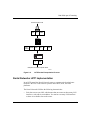
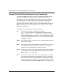
Figure 1-1 shows a Dial VPN network with both Layer 3 and Layer 2 (L2TP)
tunnels.
WAN
(PPP or
Frame relay)
Remote
node
Customer Premise
RAC
Router
Layer 3 tunnel
PPP
GW
Authorization
IP management
IP Network
PPP
Server
TP
L2
l
ne
tun
Remote
node
Authentication
accounting
Customer Premise
TMS
Router
Authentication
Accounting
Authorization
IP Management
Server
DVS0017A
Figure 1-1.
308606-14.00 Rev 00
Dial VPN Network with Layer 3 and Layer 2 Tunnels
1-3
Configuring and Troubleshooting Bay Dial VPN Services
Layer 3 Tunneling
In Layer 3 tunneling, the tunnel exists between the Network Access Server
(NAS), which is a Remote Access Concentrator (RAC), and a gateway router.
Both end points of the tunnel are within the ISP network.
Layer 2 Tunneling
In Layer 2 tunneling, the tunnel exists between the Layer 2 Tunneling Protocol
(L2TP) access concentrator (LAC), usually a remote access concentrator on the
ISP network, and the L2TP network server (LNS), a router or extranet access
switch on the customer’s home network. Rather than terminating at the remote
access concentrator, the IP tunnel extends the PPP session to the LNS, which acts
as a virtual remote access concentrator.
Note: In this guide, the term LAC refers to a remote access server with L2TP
capabilities. The term RAS refers to a remote access server without L2TP
capabilities.
Other features of L2TP include using the Internet infrastructure to support
multiple protocols and unregistered IP addresses. Because the dial-in user’s data is
tunneled at Layer 2 and above (in the ISO model), the L2TP protocol is
independent of Layer 3 information. Enterprise customers with unregistered IP
addressing schemes can also use L2TP to reach their home network.
Comparing Layer 3 and Layer 2 Features
Dial VPN supports both Layer 3 and Layer 2 tunneling on the same ISP network.
Both provide secure network access for dial-in users to their home networks.
Table 1-1 briefly compares the most significant features of both Layer 3 and
Layer 2 tunneling.
1-4
308606-14.00 Rev 00
Tunneling Overview
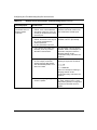
Table 1-1.
Layer 3 and Layer 2 Dial VPN Feature Implementation
Dial VPN Feature
Layer 3
Layer 2
Tunnel management
erpcd, ACP, or
RADIUS (BSAC)
erpcd, ACP, or RADIUS
(BSAC)
Protocol
Mobile IP
L2TP
Encapsulation
GRE
L2TP
Tunnel end points
NAS and gateway
LAC and LNS
Dynamic IP address
allocation
IP pooling or DHCP
IP pooling
Layer 3 protocols
supported
IP, IPX
IP
How a Dial VPN Network Functions
Any authorized remote user (using a PC or dial-up router) who has access to a
phone line and a modem can dial into your network through Dial VPN. A remote
node can be an individual user dialing in or a dial-up router (using IP) through a
public-switched telephone network (PSTN) or an ISDN connection. A remote
user can dial in to a Dial VPN network to connect either to a corporate or home
network or to a third-party ISP. Dial VPN regards these as functionally equivalent.
Figure 1-2 is a simplified illustration of one possible Layer 3 Dial VPN
configuration. In reality, a Dial VPN service provider’s network might include
several remote access servers to service a variety of dial-in users, with both Layer
3 and Layer 2 tunnels serving different types of networks. You can configure Dial
VPN so that its operation is transparent both to users and applications. You may
find it useful to draw a map of your own configuration and label the interfaces
with their IP and, if appropriate, frame relay Data Link Connection Identifier
(DLCI) addresses.
308606-14.00 Rev 00
1-5
Configuring and Troubleshooting Bay Dial VPN Services
Tunnel
domain
data
Service
provider network
Third-party
Internet
service
provider
network
TMS /erpcd
Network
server
access
server (NAS)
Gateway
PSTN
Internet
Tunnel
Remote
node
PPP
connection
User
data
CPE
Frame relay
or PPP
CPE
LAN
CPE
Third-party
ISP
RADIUS
server
Customer
network
Customer
RADIUS
server
DVS0012A
Figure 1-2.
Dial VPN Network with Connections to Different Destination Types
Figure 1-2 shows a Dial VPN service provider network with a Layer 3 tunnel. The
gateway provides connection services both to a corporate LAN and to a
third-party ISP network. This figure shows only one tunnel, but in reality Dial
VPN creates one tunnel for each dial-in connection.
In this illustration, a user at a remote node can dial in to a corporate or home
network or a third-party ISP by calling a local phone number associated with that
destination network. The network access server handles the call. The service
provider’s network uses a standard IP connection between the network access
server, shown here as a 5399 module in a 5000 MSX chassis, and the gateway. A
PPP connection or a frame relay PVC and a static route must exist between the
gateway and the customer premise equipment (CPE) router to provide a path for
packets to return to the remote node.
1-6
308606-14.00 Rev 00
Tunneling Overview
For Nortel Networks routers used with a Layer 3 Dial VPN tunnel, you must
specify an adjacent host and a static route between the gateway and the CPE, and
also between the CPE router and the remote node. (The adjacent host and static
routes do not appear in this diagram.) For an illustration of Layer 3 tunneling, see
Chapter 3.
The rest of this guide describes how to install and configure a Dial VPN service
provider network. It also indicates the requirements for the remote node and the
RADIUS and DHCP servers, with references to the documentation that explains
how to do the configuration.
Dial VPN Network Components
Installing and configuring a Dial VPN service provider network involves several
tasks, some of which you may already have completed. You must:
•
Plan the network.
•
Install and connect the network hardware.
•
Install and configure the network software.
•
Verify that the elements outside the Dial VPN network, specifically the
remote server or servers, the router on the home network, and the remote
dial-in nodes, are properly configured.
•
Power up, test, and troubleshoot your network.
See the documentation for each of these entities for information on how to install
and configure them.
This guide deals specifically with how you combine these elements into a Bay
Dial VPN network. The following sections summarize the elements of Dial VPN
networks.
Remote Dial-In Nodes
Remote nodes can be PCs (portable hosts) or dial-up routers, using PPP for
dial-up connections. The portable host must have PPP client software and a
TCP/IP or IPX protocol stack loaded.
Dial VPN supports dial-up IP (and, for Layer 3, IPX) over PPP for dial-in PC
clients and IP over PPP for dial-in routers connected to LANs.
308606-14.00 Rev 00
1-7
Configuring and Troubleshooting Bay Dial VPN Services
The following considerations apply only to Layer 2 (L2TP) tunnels:
•
If the PC or router does not have built-in L2TP software capabilities, it dials
into a LAC, which provides a tunnel across the Internet to the corporate LNS.
This type of connection is the primary focus of this guide.
•
If the PC or router is an L2TP client, that is, it has built-in L2TP capability,
the L2TP client software provides a tunnel through a network access server
across the Internet to the corporate LNS. A LAC is unnecessary with an L2TP
client.
The main difference between connecting an L2TP client and a nonclient is the
starting point of the tunnel. For an L2TP client, the tunnel begins at the PC or
router; for a non-L2TP client, the tunnel begins at the LAC. All tunnels end at the
LNS.
ISP Network Components for Layer 3 Tunnels
The devices that make up the Dial VPN service provider network can be all at the
same site or can be separated by several “hops” within the same network. A
network with Layer 3 Dial VPN tunnels can consist of a network access server
(NAS), a gateway router that serves as the tunnel end point, and a tunnel
management server.
Network Access Server (NAS)
A network access server (NAS) can be a Remote Access Concentrator
Model 8000 or a System 5000 chassis with one or more Model 5399 Remote
Access Concentrator modules. Each module is configured with a network address
belonging to the service provider’s address domain. The Remote Access
Concentrator 8000/5399 includes a dual WAN server, which can support both
analog calls and digital calls carried over ISDN. The NAS receives and processes
calls from remote nodes and routes data to remote nodes.
Note: This guide uses the term network access server (NAS) to refer to the
device that performs network access functions, such as answering dial-in user
calls, authenticating tunnel users, building tunnels, and so on. In the Dial VPN
context, this device is usually a Remote Access Concentrator (RAC). Other
documents may refer to this same device as a remote access server (RAS).
Essentially, all three terms (NAS, RAS, and RAC) refer to functionally the
same device.
1-8
308606-14.00 Rev 00
Tunneling Overview
Gateway
Used only in Layer 3 networks, the gateway can be an ASN, BLN, BLN-2, BCN,
or System 5000 MSX equipped with a Model 5380 module running BayRS
software.
The gateway connects the Dial VPN service provider’s network and the CPE
router on the remote user’s home network. The gateway performs conventional IP
routing functions configured on interfaces connected to the IP network, through
which the network access servers can be reached.
The gateway is the end point of the IP-routed tunnels that transport packets
originated by remote nodes and encapsulated by the NAS. The gateway also
connects to the CPE router on the user’s home network. The gateway is the data
terminal equipment (DTE) for frame relay PVCs or PPP connections connecting
to multivendor RFC 1490-compliant routers on the customer premises.
For a frame relay network, the connection is through a frame relay user network
interface (UNI). The gateway forwards traffic between a remote node and the
corresponding node in its home network by forwarding packets over a frame relay
PVC connecting the UNI to the IP tunnel. Thus, the gateway uses the IP tunnel
and the frame relay PVC as two links through which it can send the user traffic
from one side to the other.
With a frame relay connection, you can also configure up to 10 secondary
gateways for use as backup gateways or as a load-balancing mechanism.
The PPP connection between the gateway and the customer’s home network
functions in a similar way, except that the connection is through a PPP interface
instead of a frame relay interface.
The gateway may also act as a RADIUS client to authenticate the remote user
based on information provided from the NAS. The RADIUS client on the gateway
sends an authentication request to the RADIUS server on the home network,
which either grants or denies the request in a message to the gateway. The
gateway then returns this information to the NAS to continue the process.
308606-14.00 Rev 00
1-9
Configuring and Troubleshooting Bay Dial VPN Services
Tunnel Management Server (TMS)
The mechanism for identifying tunneled users is the tunnel management server
(TMS) that resides on a tunnel management server.
For Layer 3 tunnels, the NAS retrieves the tunnel configuration attributes from its
TMS database residing on the tunnel management server and uses them to build a
tunnel into the customer’s network. Once the tunnel is open, the user can be
authenticated at the customer’s network. Tunnel management can be either
RADIUS or erpcd-based.
•
In the RADIUS method, a RADIUS server resides at the service provider site
and manages the TMS database. The NAS and the RADIUS server
communicate using IP over the service provider network. Backup gateways
and load distribution mode require the use of the RADIUS method.
•
In the erpcd-based method, the TMS hosts a database application (the Tunnel
Management System) that controls the IP tunnel establishment attempt from
the NAS. The TMS runs on the same UNIX host as the Access Control
Protocol (ACP) software. The NAS and the TMS communicate using the
Nortel Networks proprietary Expedited Remote Procedure Call Daemon
(erpcd or Secure erpcd). Both Layer 3 and Layer 2 tunnels can use this
method.
In either method, the NAS queries the TMS database for the addressing
information it needs to construct the IP tunnel. This query is based on the user
domain name and on the policy and state information of the enterprise customer
account when the remote user dials in. As a Dial VPN network administrator, you
must provide the user domain and tunnel addressing information to the TMS
database for each enterprise customer. Chapter 5 and Chapter 6 describe the
commands you can use to provision the default TMS database.
ISP Network Components for Layer 2 Tunnels
The following sections describe the components of a network with Layer 2
tunnels. A network with Layer 2 Dial VPN tunnels also has a NAS (which may
function as either a LAC or a RAS) and a tunnel management server. The edge
router, however, does not function as a gateway; rather, the tunnel end point is the
CPE router on the customer’s home network. The network itself can have
additional components. This description pertains only to those relevant to Layer 2
tunneling.
1-10
308606-14.00 Rev 00
Tunneling Overview
L2TP Access Concentrator (LAC)
The L2TP access concentrator (LAC) resides at the ISP network. The LAC
establishes the L2TP tunnel between itself and the LNS. When the remote user
places a call to the ISP network, the call goes to the LAC. The LAC then
negotiates the activation of an L2TP tunnel with the LNS. This tunnel carries data
from the remote user to the corporate network.
For more information about the Nortel Networks implementation of the LAC in
an L2TP network, refer to Configuring L2TP Services.
Remote Access Server (RAS)
The remote access server (RAS) resides at the ISP network. If the remote host is
an L2TP client, the tunnel is established from the remote client through a RAS to
an LNS at the corporate network. In this situation, there is no need for a LAC.
The RAS does not establish the tunnel; it only forwards already tunneled data to
the destination.
Tunnel Management Server (TMS)
The ISP network must have a mechanism for identifying L2TP tunneled users so
that the LAC can construct the L2TP tunnel. Dial VPN uses a mechanism called a
tunnel management server (TMS); other vendors may use a different method. The
TMS has the same function as for Layer 3 tunnels.
Customer/Home/Internet Service Provider Network
The Dial VPN network interacts with the customer premise equipment (CPE) and
the RADIUS authentication server and the RADIUS accounting server on the
customer’s destination network.
Customer Premise Equipment (CPE)
The CPE is a router or extranet switch that connects to the Dial VPN network by
means of frame relay PVCs or a PPP connection. The CPE routes traffic from the
remote nodes to hosts on the home network and from the home network hosts
back to remote nodes.
308606-14.00 Rev 00
1-11
Configuring and Troubleshooting Bay Dial VPN Services
Enterprise subscribers of this service must configure the CPE router to allow
routing to occur between the remote nodes and the hosts on the home network.
For a Layer 3 frame relay circuit, a frame relay PVC, a static route, and (for a
Nortel Networks or other non-Cisco router), adjacent host designation must exist
between the CPE and the gateway router on the Dial VPN network. For frame
relay, all Dial VPN circuits must be in the same service record. PPP circuits have
similar requirements, except for the PVC and service record.
L2TP Network Server (LNS)
The L2TP network server (LNS) is a router that resides at the customer’s home
network and serves as the termination point for Layer 2 (L2TP) tunnels and
sessions.
The LNS authenticates PPP connection requests and allows end-to-end PPP
tunneled connections. An LNS may also work in conjunction with a RADIUS
server to authenticate dial-in users.
An LNS can accommodate multiple users, each with his or her own L2TP session.
The L2TP session is the virtual end-to-end connection over which the LAC sends
data to the LNS.
In Layer 2 tunneling, the CPE router is also the LNS. For more information about
the Nortel Networks LNS, see Configuring L2TP Services.
RADIUS Authentication Server
The RADIUS authentication server on the customer’s network is a network access
security system. It uses a locally stored and maintained database that contains all
user authentication and network service access information to authenticate dial-in
user access requests.
Note: The Dial VPN RADIUS server for Layer 3 tunnels must be on a
separate physical device from any RADIUS server for Layer 2 tunnels or for
switched services. The RADIUS server for Layer 2 tunnels can be the same
physical device as for any dial services RADIUS server.
1-12
308606-14.00 Rev 00
Tunneling Overview
The RADIUS server has three main functions in a Dial VPN L2TP network:
•
Authenticating remote users
•
Assigning IP addresses to remote users
•
Providing accounting services for corporate billing
For Layer 3 tunnels, the RADIUS client of this server resides on the gateway.
The RADIUS client on the ISP network generates a RADIUS authentication
request to the appropriate RADIUS server. This request contains the user
authentication information. The CPE receives the authentication request and
forwards it to the RADIUS server.
Once the user is authenticated, the RADIUS server grants access to the remote
node by returning an authentication accept packet with RADIUS authorization
information to the gateway through the CPE.
For a Layer 3 tunnel, the gateway then forwards the user authentication to the
NAS, which initiates an IP tunnel to the gateway using Mobile IP protocol
mechanisms.
For an L2TP tunnel, the RADIUS server database centralizes the authentication
function, eliminating the need to configure each LNS with user names and
passwords. It also assigns an IP address to the remote host to identify the host and
ensure that it is part of its own subnet.
For more information about the Nortel Networks implementation of RADIUS
user authentication and accounting, see Configuring RADIUS and the BaySecure
Access Control Administration Guide.
RADIUS Accounting Server
The RADIUS accounting server tracks when users start and end their dial-in
connections and acquires statistics about each session. BaySecure Access
Control™ fully supports RADIUS accounting and provides the network access
server with RADIUS accounting information for every active dial-in session. The
RADIUS accounting server can provide accounting services for the corporate
network, calculating billing charges. For a full description of BaySecure Access
Control and the RADIUS functions it supports, see the BaySecure Access Control
Administration Guide.
308606-14.00 Rev 00
1-13
Configuring and Troubleshooting Bay Dial VPN Services
DHCP Server
If you implement the optional Dynamic Host Configuration Protocol (DHCP) as a
way of dynamically assigning IP addresses to dial-in users, you must also
configure a DHCP server on the customer’s network. For a detailed description of
using DHCP, see Chapter 8 in this guide.
Additional Planning Information
Appendix A contains a network planning worksheet that you can use in
determining how to configure the BayRS side of your Dial VPN network. You
may not have enough information yet to complete this worksheet, but if you fill it
in as you go along, it can provide documentation for your network. You may also
find this information useful when changing or troubleshooting your network.
Where to Go Next
For a description of how a packet moves through a Dial VPN network and other
background information that can help you visualize the data flow through the
network, go to Chapter 2 for Layer 2 tunneling or Chapter 3 for Layer 3 tunneling.
For information about configuring Dial VPN, go to Chapter 4.
For troubleshooting information, go to Appendix C, “Troubleshooting.”
For configuration tips and techniques, go to Appendix D, “Tips and Techniques.”
1-14
308606-14.00 Rev 00
Chapter 2
Dial VPN Layer 2 Tunneling
This chapter describes how a Layer2 Dial VPN tunnel functions. Among these
concepts are how a data packet sent from a remote node using PPP moves through
a Dial VPN service provider’s network to a corporate or “home” network via a
frame relay or PPP connection. It also explains how the Dial VPN tunnel forms a
path to move data quickly and efficiently to and from the remote node through the
Dial VPN service provider’s IP backbone network.
Dial VPN uses encapsulation technologies and the Layer 2 Tunneling Protocol
(L2TP) to provide a secure pathway for remote users to exchange data with their
corporate home network. Regardless of where a remote node is located, it can dial
in to its Dial VPN service provider and connect to the home network.
Figure 2-1 shows the path of a packet in a Layer 2 tunnel. The NAS functions as
an L2TP access concentrator (LAC) and the other tunnel end point is the CPE
router or extranet switch on the customer’s home network. That router or switch is
the L2TP network server (LNS), which terminates all L2TP tunnels and sessions
with that network. In this figure, the dotted line shows the path of the packet
through the tunnel; the Dial VPN service provider network is the ISP network.
308606-14.00 Rev 00
2-1
Configuring and Troubleshooting Bay Dial VPN Services
ISP network
PC
Frame relay
connection
LAC
Remote
host
Tunnel
PPP
connection
Corporate network
LNS
Data
RADIUS
server
No L2TP
functionality
TMS
L2T0003A
Figure 2-1.
Layer 2 Tunnel Packet Path
Note: If the dial-in node is configured with an L2TP client, that client serves
as the LAC, and the RAC serves the function of a normal network access
server. In this guide, most of the descriptions use the Remote Access
Concentrator as the LAC for Layer 2 tunnels.
Building a Network for Layer 2 Tunneling
The steps that follow provide a suggested order for configuring your network for
Dial VPN Layer 2 tunneling. For detailed information about each of these steps,
see Chapters 4 through 10.
1.
2-2
At the ISP network, configure the following:
•
Remote Access Concentrator, serving as the L2TP access concentrator
(LAC)
•
Tunnel management server (TMS) on the erpcd server for the
erpcd-based solution
•
Access Control Protocol (ACP) server (only for the erpcd-based solution)
•
Edge router capable of connecting to the LNS on the customer’s home
network with frame relay or PPP
308606-14.00 Rev 00
Dial VPN Layer 2 Tunneling
2.
Install and configure any intermediate nodes on the WAN.
The WAN can include intermediate nodes. For installation and startup
information, refer to the hardware documentation for each device.
3.
Install the software for the tunnel management server, Remote Access
Concentrator, and (for the erpcd-based solution) Access Control Protocol
on the host that serves as the load host for the Remote Access
Concentrator.
For installation instructions, see the Remote Access Concentrator
documentation.
4.
Load the operating software onto the Remote Access Concentrator and
boot the Remote Access Concentrator.
For detailed descriptions of the boot procedures, see the Remote Access
Concentrator documentation.
5.
Configure the Remote Access Concentrator software, as described in
Chapter 4, to handle PPP dial-in calls from remote nodes, determine
whether they are tunnel clients, and route them appropriately.
6.
Configure the TMS (including the authentication type) by adding an
entry in the TMS for each domain in the TMS database. See Chapter 5
and Chapter 6 for more information.
When configuring the TMS, you can choose either local or remote
authentication. Dial VPN uses a RADIUS server on the customer’s home
network to provide authentication and assign IP addresses.
For DHCP address allocation, configure the TMS with the DHCP parameters,
as described in Chapter 5.
7.
308606-14.00 Rev 00
Establish a connection between the edge router on the Dial VPN network
and a CPE router (the LNS) on the home network using frame relay or
PPP.
2-3
Configuring and Troubleshooting Bay Dial VPN Services
8.
Make sure that the home network is configured to connect to the Dial
VPN network.
Specifically, ensure that:
•
The RADIUS server on the home network is configured to work with the
RADIUS client on the Dial VPN network. If dynamic IP address
allocation or DHCP is enabled, the RADIUS or DHCP server must have
an allocated pool of addresses for authenticated dial-in users and have
RADIUS accounting enabled.
•
The CPE router that is the end point of Layer 2 tunnels is configured as
the LNS and is configured with a frame relay or PPP connection to the
ISP network (including a static route and an adjacent host if the CPE
router is not a Cisco device).
For instructions on configuring the LNS, see Configuring L2TP Services.
•
9.
Any shared information, such as passwords, “secrets,” or phone numbers,
is consistent across the link.
Individually test each network component, then test the entire system.
L2TP Packet Encapsulation
The dial-in user sends PPP packets to the LAC, which encapsulates these
incoming packets in an L2TP packet and sends it across an IP network through a
bidirectional tunnel. After the LNS receives the packets, it decapsulates them and
terminates the PPP connection.
Figure 2-2 shows how data is encapsulated for transmission over an L2TP tunnel.
2-4
308606-14.00 Rev 00
Dial VPN Layer 2 Tunneling
Remote user places a call
PPP
IP
DATA
LAC
Layer 2
protocol
IP/UDP
PPP
L2TP
IP
DATA
LNS
IP
DATA
Data packet moves to the corporate network
L2T0005A
Figure 2-2.
L2TP Packet Encapsulation Process
Nortel Networks L2TP Implementation
In an L2TP tunnel, the Nortel Networks router or extranet switch on the home
network is the LNS. LNS software operates on the BLN, BCN, and ASN
platforms.
The Nortel Networks LNS has the following characteristics:
•
308606-14.00 Rev 00
Each slot can act as an LNS, which means that one router can have many LNS
interfaces, each with its own address. You can have as many LNS interfaces
as there are available slots on the router.
2-5
Configuring and Troubleshooting Bay Dial VPN Services
•
The LNS performs user authentication with a RADIUS server to prevent
unauthorized users from accessing the network.
•
The LNS accepts only incoming calls; it does not place calls to the LAC.
•
The Nortel Networks L2TP implementation supports only IP traffic through
the L2TP tunnel. The LNS supports only numbered IP addresses.
•
The router interface between the ISP and the home network (see Figure 2-4) is
a leased line operating with frame relay or PPP (including PPP multilink).
Nortel Networks recommends that you use a high-speed link, such as T1, for
the leased connection.
•
The LNS terminates PPP multilink and PPP encapsulated data within an
L2TP packet.
•
The LNS operates with the LAC implementation configured on the Nortel
Networks Model 8000/5399 Remote Access Concentrator.
•
The host (PC or router) dialing into the ISP network can be on the same
subnet as the IP interface on the LNS.
•
The LNS supports RIP. RIP is particularly useful when the remote host is a
router, because it enables the LNS to learn routing information from the
remote router.
For a summary of how to configure the LNS, see Chapter 8 of this guide. For
complete instructions on how to configure a Nortel Networks router as an LNS,
see Configuring L2TP Services.
Tunnel Management in L2TP Tunnels
The Nortel Networks tunnel management server (TMS), which resides at the ISP
network, stores the TMS database. This database contains the remote users’
domain name, the IP address information of each LNS, and other tunnel
addressing information that the network administrator configures. The LAC
requests this information from the TMS to construct the L2TP tunnel.
2-6
308606-14.00 Rev 00
Dial VPN Layer 2 Tunneling
When the LAC receives a call, it forwards the domain name to the TMS. The
domain name is the portion of the user’s address that specifies a particular
location in the network. For example, if the user name is [email protected], abc.com
is the domain name. The TMS looks up the domain name and verifies that the
remote user is an L2TP user. The TMS also provides the LAC with the addressing
information required to establish a tunnel to the correct LNS.
Note: The domain name referred to in this guide is a domain identifier that
does not follow a specific format. It is not related to any Domain Name System
(DNS) protocol requirements.
Security in an L2TP Network
You can configure two layers of security in an L2TP network:
•
Tunnel authentication
Tunnel authentication is the process of negotiating the establishment of a
tunnel between the LAC and the LNS.
•
User authentication
The network administrator at the corporate site can configure a RADIUS
server with the names and passwords of authorized users. The server’s
database centralizes the authentication function, eliminating the need to
configure each LNS with user names and passwords.
When the LNS receives a call, it forwards the user information to the
RADIUS server, which verifies whether the user is authorized to access the
network.
You can also configure the LNS to perform user authentication if a RADIUS
server is not part of the network configuration.
The following paragraphs describe the Nortel Networks implementation of tunnel
and user authentication.
Tunnel Authentication
For Dial VPN Layer 2 tunnel security purposes, you must enable the LNS to
perform tunnel authentication. Tunnel authentication is the process of negotiating
the establishment of a tunnel.
308606-14.00 Rev 00
2-7
Configuring and Troubleshooting Bay Dial VPN Services
During tunnel authentication, the LNS identifies the L2TP client or LAC by
comparing the LAC’s tunnel authentication password with its own password. If
the passwords match, the LNS permits the LAC to establish a tunnel.
The LAC does not send the tunnel authentication password as a plain-text
message. The exchange of passwords works much like the PPP Challenge
Handshake Authentication Protocol (CHAP). When one side receives a challenge,
it responds with a value that is calculated based on the authentication password.
The receiving side matches the value against its own calculation. If the values
match, authentication is successful.
Tunnel authentication occurs in both directions, which means that the LAC and
LNS both try to verify the other’s identity.
You can enable tunnel authentication on the Nortel Networks LNS. If tunnel
authentication is disabled, which is the default, the LNS sends a default challenge
response to the LAC during the authentication process so that the tunnel can be
established. The LNS cannot send outgoing calls, so it cannot initiate tunnel
authentication.
During tunnel authentication, the following exchange of messages takes place:
1.
The LAC sends a tunnel setup message, called the start control connection
request (SCCRQ) message to the LNS. This message includes a challenge to
the LNS.
2.
The LNS replies with a tunnel response, a challenge response, and its own
challenge message. This is called the start control connection reply (SCCRP)
message.
3.
The LAC replies with a challenge response that includes its tunnel
authentication password. This is the start control connection connected
(SCCCN) message.
4.
If this same password is configured for the LNS, the LNS grants approval to
the LAC to establish a tunnel.
Figure 2-3 shows tunnel authentication and the control messages.
2-8
308606-14.00 Rev 00
Dial VPN Layer 2 Tunneling
ISP network
Corporate network
PPP connection
LNS
LAC
SCCRQ
tunnel request and challenge
SCCRP
tunnel response, challenge response,
and LNS challenge
SCCCN
challenge response
L2T0006A
Figure 2-3.
Tunnel Authentication Control Messages
After tunnel authentication is complete, it need not be repeated for other calls to
the same LAC.
RADIUS User Authentication
RADIUS user authentication is enabled by default on the Nortel Networks LNS;
you must configure this feature so that the LNS can validate the remote user’s
identity before allowing access to the network.
The network administrator at the corporate site must configure a RADIUS server
with the names and passwords of authorized users. When the LNS receives a call,
it forwards an authentication request with the user information to the RADIUS
server, which verifies whether the user is authorized. If the user is permitted
access to the network, the RADIUS server replies with an acknowledgment
message and the appropriate IP address information for that user to make a
connection.
For more information about configuring Nortel Networks routers as RADIUS
servers, see Configuring RADIUS.
308606-14.00 Rev 00
2-9
Configuring and Troubleshooting Bay Dial VPN Services
RADIUS Accounting
The RADIUS server can provide accounting services in addition to its
authentication services. RADIUS accounting is enabled by default on the Nortel
Networks LNS.
The RADIUS accounting server calculates billing charges for an L2TP session
between the remote user and the LNS. To determine these charges, the server uses
information that it receives from the LNS, such as the status of each call and the
number of packets sent during the session. Using this data, the RADIUS server
determines billing charges, which the network administrator can use to manage
network costs.
The primary RADIUS accounting server can be the same server as the
authentication server or it can be a different server.
For more information about RADIUS accounting, refer to Configuring RADIUS.
L2TP IP Interface Addresses
When configuring the Nortel Networks LNS, you must configure an IP address
for every slot that has an L2TP interface. This address is referred to as the L2TP
IP interface address. The L2TP IP interface can be any valid IP address.
The L2TP IP interface address is internal to the LNS. When communicating with
the remote user, the LNS associates the user’s IP address, which is assigned by the
RADIUS server, with the L2TP IP interface address that you configured.
The L2TP IP interface address and the RADIUS-assigned IP address do not have
to be in the same subnet.
2-10
308606-14.00 Rev 00
Dial VPN Layer 2 Tunneling
Remote Router Configuration
If the host at the remote site is a Nortel Networks router, you may need to
configure a dial-on-demand circuit for the remote router’s dial-up interface to the
LAC at the ISP network.
Enable RIP on both the dial-on-demand circuit and the attached LAN interface of
the remote router, so that the LNS can learn routing information from the remote
router. To avoid unnecessarily activating the circuit because of RIP packets,
enable dial-optimized routing for the dial-on-demand circuit.
In addition, configure a default or static route for the remote router, which uses the
next-hop address that corresponds to the L2TP IP interface address of the LNS.
This default or static route enables the remote router to deliver L2TP packets to
the LNS.
Starting an L2TP Session
The connection process for Layer 2 tunnels is similar to that for Layer 3, but the
end points of the tunnels are different. In L2TP tunneling, the end point of the PPP
connection from a LAC or a remote access server (RAS) extends to an L2TP
network server (LNS). Multiple users can communicate through a single tunnel
between the same LAC and LNS pair. Each user transmits and receives data in an
individual L2TP session.
Packets flow across an L2TP tunnel during an L2TP session. An L2TP session is
created when an end-to-end WAN connection is established between the remote
host and the LNS.
The L2TP portion of the packets sent through the tunnel contains a header with a
call ID field (also called a session ID) and a tunnel ID field. The call ID field,
which indicates the session that the WAN packet belongs to, is negotiated between
the LAC and the LNS when the L2TP call is set up. The tunnel ID specifies the
tunnel that the L2TP session is using.
In addition to the fields in the header, the L2TP packet contains a call serial
number, which is a unique number for each L2TP call. This number matches the
call to the L2TP session.
308606-14.00 Rev 00
2-11
Configuring and Troubleshooting Bay Dial VPN Services
Examples of L2TP Tunnels
Figure 2-4 shows an L2TP network that uses a LAC to connect to the LNS. The
tunnel is between the LAC and the LNS.
ISP network
PC
Frame relay
connection
LAC
Remote
host
LNS
Tunnel
PPP
connection
Corporate network
Data
RADIUS
server
No L2TP
functionality
TMS
L2T0003A
Figure 2-4.
L2TP Network Using a LAC
Figure 2-5 shows an L2TP network that uses a RAS to connect to the LNS. The
tunnel is between the PC (the L2TP client) and the LNS.
ISP network
Remote
host
Frame relay
connection
RAS
LNS
Tunnel
PC
Corporate network
Data
RADIUS
server
L2TP
client
L2T0004A
Figure 2-5.
2-12
L2TP Network Using a RAS
308606-14.00 Rev 00
Dial VPN Layer 2 Tunneling
Making a Connection Across an L2TP Network
The following steps explain how a remote user connects across an L2TP network
that includes a Nortel Networks LAC, TMS, and LNS. (See Figure 2-4.)
1.
The remote user dials a LAC at the local ISP network to establish a PPP
connection to the corporate network.
In the call, the user includes any required information, for example, a user
name, including a domain name and a password. When dialing in, the user
enters a name, for example, [email protected]; jdoe is the user name and
abc.com is the domain name.
2.
The LAC receives the call and passes the domain name to the TMS.
If the TMS finds a match for the domain name, a tunnel can be created. The
TMS also checks the number of current connections so that they will not
exceed the maximum number allowed.
If the user is not a tunnel candidate, as determined by the domain name, the
LAC assumes that the remote host is making a regular dial-in request and
authenticates the user accordingly.
3.
The LAC tries to establish an L2TP tunnel with the LNS.
For the LAC to send a tunnel request to the LNS, it needs the address of the
LNS. The LAC requests the address from the TMS. It then checks for this
address in its own routing table. After obtaining the address, the LAC sends a
tunnel request to the LNS. The LNS may perform tunnel authentication, if
configured to do so. If the LAC and LNS complete tunnel authentication
successfully, the LAC establishes the tunnel.
4.
After the tunnel is established, the LAC forwards the remote user’s name to
the LNS, which verifies the user’s identity with the corporate RADIUS server.
If the RADIUS server recognizes the user name, it replies with an
acknowledgment and an IP address that it assigns to the remote user for the
duration of the call. This IP address identifies the remote user who may not
have an address of his own.
5.
After the remote user is successfully authenticated, the user has an end-to-end
PPP connection to the corporate network over the Internet.
The tunnel can now carry a user session during which the LAC and the LNS
exchange PPP packets.
308606-14.00 Rev 00
2-13
Configuring and Troubleshooting Bay Dial VPN Services
When Does Dial VPN Tear Down the Tunnel?
The LAC brings down the tunnel for any one of the following reasons:
•
A network failure occurs.
•
The LAC or other equipment at the ISP is not operating properly. If the LAC
fails, all tunnel users are disconnected.
•
There are no active sessions inside the tunnel.
An individual session ends when a remote user disconnects the call, but
multiple sessions can run inside a single tunnel.
•
The system administrator at the ISP terminates the user connection.
•
The LAC is not responding to a Hello packet from the LNS.
For the LAC to reestablish a tunnel, the remote user must place a new call.
If the LAC fails, all tunnel users are disconnected and the active user counts are
decremented. However, there is no quick way to determine when a LAC fails. The
logging connection may not be reset until after new tunnel users have connected.
When a LAC starts, one of the first things it does is open its ACP-logging
connection. When a new logging connection opens, TMS decrements the
appropriate counts for each domain that had a user connected to the LAC. If this is
the first time the LAC has come up, then there will be nothing to decrement.
Note: If you enter the reset security command, a new user who tries to make
a connection with the LAC causes the maximum number of users count to
decrement, even though users with existing connections are still connected.
This means that the maximum number of users count may be exceeded. As
users with existing connections disconnect, the count will synchronize and
correspond to the actual number of users connected.
If the TMS fails, a LAC can detect the failure through the failure of the logging
connection. The LAC falls back to secondary servers, if any. Unless the database
is shared by the TMS servers, the count of current users is lost.
If the TMS database runs out of disk space while tms_dbm is running, the user
sees an error message. The error message may not state what caused the error. If
there is a shortage of disk space and erpcd cannot create a lock file or add a LAC
to the TMS database, TMS generates a syslog message and the user cannot make a
connection to the LAC.
2-14
308606-14.00 Rev 00
Chapter 3
Dial VPN Layer 3 Tunneling
This chapter describes how a Layer 3 Dial VPN tunnel functions. Among these
concepts are how a data packet sent from a remote node using the point-to-point
protocol (PPP) moves through a Dial VPN service provider’s network to a
corporate or “home” network via a frame relay or PPP connection. It also explains
how the Dial VPN tunnel forms a path to move data quickly and efficiently to and
from the remote node through the Dial VPN service provider’s IP backbone
network.
Dial VPN uses the Generic Routing Encapsulation (GRE) protocol and the Mobile
IP protocol to provide a secure pathway for remote users to exchange data with
their corporate home network over a Layer 3 tunnel. Regardless of where a remote
node is located, it can dial in to its Dial VPN service provider and connect to the
home network.
For example, Figure 3-1 shows how a packet moves in an erpcd-based network
from the NAS, through the Layer 3 tunnel to the gateway, across a frame relay
connection, and on to the home network. In this figure, the dotted line shows the
path of the packet through the tunnel; the Dial VPN service provider network is
the ISP network.
308606-14.00 Rev 00
3-1
Configuring and Troubleshooting Bay Dial VPN Services
BayDVS service
provider network
NAS
PPP
connection
Gateway
Tunnel
Frame relay
connection
Corporate
"home"
network
Data
Remote
node
Tunnel
management
server/ACP server
DVS0001A
Figure 3-1.
Layer 3 Tunnel Packet Path
Building a Network for Layer 3 Tunneling
The steps that follow suggest an order for configuring your network. For detailed
information about each of these steps, see Chapters 4 through 9.
1.
3-2
At the ISP network, configure the following:
•
Remote Access Concentrator, serving as the network access server (NAS)
•
Tunnel Management Server (TMS), either on the UNIX erpcd server for
the erpcd-based solution or on the service provider network RADIUS
server for the all-RADIUS solution
•
Access Control Protocol (ACP) server (only for the erpcd-based solution)
•
Nortel Networks router that serves as the gateway to the remote user’s
home network
308606-14.00 Rev 00
Dial VPN Layer 3 Tunneling
2.
Install and configure any intermediate nodes on the WAN.
The WAN can include intermediate nodes. For installation and startup
information, refer to the hardware documentation for each device.
3.
Install the software for the tunnel management server, Remote Access
Concentrator, and (for the erpcd-based solution) the Access Control
Protocol on the UNIX host that serves as the load host for the Remote
Access Concentrator.
For installation information, see the Remote Access Concentrator
documentation.
4.
Load the operating software onto the Remote Access Concentrator from
the UNIX load host and boot the Remote Access Concentrator.
For detailed descriptions of the boot procedures, refer to the Remote Access
Concentrator documentation.
5.
Configure the Remote Access Concentrator software, as described in
Chapter 4, to handle PPP dial-in calls from remote nodes, determine
whether they are tunnel clients, and route them appropriately.
6.
For the all-RADIUS solution, install and configure the RADIUS server
on the service provider network to support the TMS database.
For more information about installing and configuring RADIUS servers on
the ISP network, see Chapter 6.
7.
Configure the TMS (including the authentication type) by adding an
entry in the TMS for each domain in the TMS database. Refer to
Chapter 5 and Chapter 6 for more information.
When configuring the TMS, you can choose either local or remote
authentication. For both the erpcd-based and the all-RADIUS solutions, Dial
VPN uses remote authentication; that is, a RADIUS server on the customer’s
home network provides authentication and assigns IP addresses.
For DHCP address allocation, configure the TMS with the DHCP parameters,
as described in Chapter 5.
308606-14.00 Rev 00
3-3
Configuring and Troubleshooting Bay Dial VPN Services
8.
Configure the gateway, including the RADIUS client, using Site Manager,
then boot the gateway.
Configure the gateway with an IP connection to the Dial VPN network and a
frame relay or PPP connection to the CPE router on the remote user’s home
network. Configure a RADIUS client on the gateway. For information on
configuring the gateway, see Chapter 7.
9.
Establish a connection between a gateway on the ISP network and a CPE
router on the home network using frame relay or PPP.
10. Make sure that the home network is configured to connect to the Dial
VPN network.
Specifically, ensure that:
•
The RADIUS server on the home network is configured to work with the
RADIUS client on the Dial VPN network. If dynamic IP address
allocation or DHCP is enabled, the RADIUS or DHCP server must have a
pool of addresses allocated for authenticated dial-in users. For dynamic IP
address allocation, you must have RADIUS accounting enabled.
•
The CPE router is configured with a frame relay or PPP connection to the
Dial VPN gateway (including a static route and an adjacent host if the
CPE router is not a Cisco device), and a separate but similar frame relay
or PPP connection to the RADIUS client on the gateway.
•
Any shared information, such as passwords, “secrets,” or phone numbers,
is consistent across the link.
Note: The Dial VPN RADIUS server for Layer 3 tunnels must be on a
separate physical device from any RADIUS server for Layer 2 tunnels or for
dial services. The RADIUS server for Layer 2 tunnels can be the same
physical device as any dial services RADIUS server.
11. Individually test each network component, then test the entire system.
3-4
308606-14.00 Rev 00
Dial VPN Layer 3 Tunneling
How Tunnel Management Works
Tunnel management operates differently on erpcd-based and RADIUS-only
networks, but the end result is the same.
Tunnel Management in an erpcd-Based Network
For an erpcd-based network, the tunnel management server (TMS) runs on the
same host as the Remote Access Concentrator (erpcd) and Access Control
Protocol (ACP) software. The TMS verifies that the user at the remote node is a
Dial VPN user. If the domain portion of the user name exists in the TMS database,
ACP increases the number of current users by one and sends a Grant message to
the NAS. The Grant message contains the tunnel addressing information needed
to send a packet from the remote node to the home network.
The Grant message contains the following information, which is stored in the
TMS database:
•
Remote node’s domain name
•
Domain name information server (DNIS) -- for Model 8000/5399 platforms,
the DNIS is the called number; for other platforms, it is 0 (zero)
Note: The default value for the DNIS is 0. The NAS administrator can change
this value.
•
Home agent’s IP address on the gateway (the IP address of the gateway end of
the IP tunnel)
•
Current number of users
•
Type of connection between the ISP network’s edge router or gateway and the
CPE router on the remote node’s home network
•
Primary and secondary RADIUS server IP addresses
•
Authentication protocol information
For each tunnel user, the NAS sends this information to the RADIUS client on the
gateway, which in turn sends an authentication and address request to the
RADIUS server on the remote node’s home network. When the RADIUS server
responds, authenticating the user, the NAS establishes the tunnel.
308606-14.00 Rev 00
3-5
Configuring and Troubleshooting Bay Dial VPN Services
Tunnel Management in an All-RADIUS Network
The all-RADIUS solution integrates the TMS database functions into the
RADIUS server that resides on the service provider network. This RADIUS
server recognizes the format of the VPN identifier in the user name and returns
tunnel information to the NAS. The NAS uses the tunnel information to establish
a connection to the gateway. Once the connection is made, the user authentication
information is forwarded to the indicated authentication server.
Refer to Chapter 5 for more information about the contents of the TMS database.
How the TMS Database Works
The TMS database (by default, UNIX ndbm) resides on the tunnel management
server, which resides on the service provider’s network. The main function of this
database is to verify the user name (or domain) information supplied by the NAS.
It also supplies the NAS with the tunnel addressing information (in the Grant
message) that it needs to create a tunnel for a remote user. The Dial VPN
administrator enters the domain information and the tunnel addressing
information into the database as part of the TMS configuration process.
When the TMS receives a lookup request from the NAS, it parses the user name
into the user and domain name and DNIS, and creates a Domain/0 or
Domain/DNIS key. The TMS database uses this key to find a match in the
database with the supplied user name. If the key matches an existing entry, the
TMS checks to make sure that the maximum number of users is less than the
configured maximum. If so, the TMS sends a Grant message indicating that this is
a Dial VPN user. The Grant message contains the tunnel addressing information.
3-6
308606-14.00 Rev 00
Dial VPN Layer 3 Tunneling
Since ndbm does not have a locking feature, Nortel Networks has implemented
application-level locking to prevent users from updating the database while others
are using it. The lock files are created in the UNIX install directory.
Note: The erpcd and tms_dbm utilities use a common library of functions (in
tms_lib.c) to access the database. If you replace the database and provide
access to it through the same library function interface, as required, the same
commands will work. You can replace the default database engine with a
standard UNIX relational database, such as Sybase, Informix, or Oracle, or
with one you have created yourself. For information about how to replace the
default TMS database, contact the Nortel Networks Technical Solutions
Center.
Dynamically Allocating IP Addresses
Dial VPN lets you choose between two methods of dynamic IP address allocation:
•
Dynamic Host Configuration Protocol (DHCP) requires its own server and
allocates IP addresses for a configurable, renewable period, called a lease.
•
IP address pooling uses the Dial VPN RADIUS server and allocates an IP
address from a configured pool for the duration of the user’s dial-in session.
The following sections describe each of these methods.
Using DHCP for Dynamic IP Address Allocation
This method requires a DHCP server on the home/corporate network. This server
communicates with a DHCP client proxy residing on the gateway. The server
dynamically allocates an IP address for a dial-in user when the client proxy
requests one.
Based on RFC 2131 and its extensions, DHCP provides a scalable method of
dynamically allocating IP addresses to remote users and a way of managing the IP
addresses dynamically assigned to dial-in users. This implementation supports:
•
Standard DHCP operation, as described in RFC 2131
•
Interoperation with standard DHCP servers
•
Use of both primary and secondary DHCP servers
•
DHCP leases with as many users as there are tunnels
308606-14.00 Rev 00
3-7
Configuring and Troubleshooting Bay Dial VPN Services
•
Both Dial VPN (tunneled) and non-tunneled users
•
Getting IP addresses through either the local or the remote DHCP client
proxy, in addition to other methods that Dial VPN supports, depending on
how the Dial VPN subscriber is provisioned
How DHCP Works
DHCP implements the concept of IP address leasing. An authenticated dial-in
user receives an exclusive right to use an assigned IP address for a specific,
configurable period of time, called a “lease.” When this lease expires, the DCHP
client proxy can renew the lease or let it lapse, returning the IP address to the pool.
DHCP lets a network manager specify a range of assignable IP addresses without
requiring that each IP address be tied to a specific MAC (hardware) address. The
DHCP server leases an IP address to each dial-in user and dynamically maintains
a table that links a user’s IP and MAC addresses. For users who need a fixed IP
address, a network manager can also specify a permanent assignment. A single
NAS can communicate and maintain DHCP leases with as many DHCP servers as
there are ports on the NAS (up to 48 or 62, depending on the model).
When a remote user dials in to a network access server (NAS), Dial VPN
performs the usual authentication functions. When the gateway returns the Mobile
IP (MIP) authentication response to the NAS, however, the NAS sends the
gateway a MIP dynamic address allocation (DAA) request. The gateway sends a
DHCP discover request to the DHCP server on the home network, and the server
responds with an acknowledgment (ACK) if the request is successful. The
gateway then sends the MIP DAA response back to the NAS, and the rest of the
negotiation proceeds as usual. Figure 3-2 shows the entire process.
3-8
308606-14.00 Rev 00
Dial VPN Layer 3 Tunneling
Remote
Node
NAS
TMS
RADIUS
Server
Gateway
Accounting
Server
DHCP
Server
Local
Node
Connect
LCP negotiation
CHAP initiation
Auth/Info Req
Grant w/info
MIP authentication request
Auth Req
Auth Resp w/info
Acct Start
MIP authentication response
Acct Response
MIP DAA request
DHCP discover/request
DHCP response/ack
MIP DAA response
MIP registration request
MIP registration response
CHAP completion
NCP negotiation
Open Communication
Disconnect
Terminate msg
MIP terminate request
MIP terminate response
MIP HAA request
MIP DAA response
MIP DAA
Figure 3-2.
Acct Stop
Acct response
Address release
Address response
DHCP
DVS0009C
DHCP Operational Timeline
308606-14.00 Rev 00
3-9
Configuring and Troubleshooting Bay Dial VPN Services
Using RADIUS for Dynamic IP Address Allocation
Each dial-in user retains exclusive uses of a unique IP address for the duration of
the dial-in session. Dial VPN relies on the Nortel Secure Access Control (BSAC)
RADIUS server on the user’s home network to provide those addresses, allocating
them either statically or dynamically. In static allocation, the RADIUS
administrator assigns specific addresses for specific users. In dynamic allocation,
the administrator allocates a pool of IP addresses from which the RADIUS server
selects an address to assign.
The network administrator configures the IP address of a RADIUS server on the
home network that uses dynamic address allocation and also enables dynamic
address allocation on the gateway for that server connection.
When a user dials in to a network using dynamic address allocation, RADIUS
authenticates the user and assigns an IP address from the pool. RADIUS also
maintains a database of assigned addresses. This prevents duplicate assignments if
the server fails.
When the connection ends, the released IP address returns to the pool, at the end
of the assignment queue.
To implement dynamic IP address allocation, Dial VPN requires that the BSAC
software be installed on the RADIUS server on the customer’s home network.
BSAC is a robust implementation of the draft IETF RADIUS specification,
compliant with RFC 2058 and RFC 2059.
For information about BaySecure, see the BaySecure Access Control
Administration Guide.
How Dynamic IP Address Allocation Works
Dial VPN implements dynamic IP address assignment using the Site Manager and
BaySecure Access Control (BSAC). Using Site Manager, the ISP network
administrator first enables RADIUS accounting on the gateway.
3-10
308606-14.00 Rev 00
Dial VPN Layer 3 Tunneling
The BSAC (RADIUS) administrator at the customer’s site must enter one or more
IP address ranges to be used as a pool of assignable addresses. For each remote
user, the RADIUS administrator can enter either a specific IP address or allow the
assignment of an IP address from the pool. The administrator can, in fact, set up a
standard profile with “assign from pool” specified, and apply this profile to many
users at once.
The Current Users display identifies the active users and their assigned IP
addresses, so that the RADIUS administrator can tell which user has which
address. In addition, the administrator can release any assigned address that is no
longer in use by selecting that address and clicking on Clear. For more
information about assigning and managing IP addresses, see Configuring
RADIUS.
Note: Dynamic address assignment is not available for IPX.
Assigning Addresses
All available IP addresses are in a queue. The first address in the queue is the first
one assigned. Released addresses return to the end of the queue for reassignment.
RADIUS saves all current address assignments in a database to prevent duplicate
address assignments if the server fails.
The gateway on the ISP network is a client of the RADIUS server on the
customer’s network; that is, it provides a service to the dial-in user, such as PPP or
Telnet®. The client is responsible for passing user information to the designated
RADIUS server. The RADIUS server receives the request and returns a response
to the client that it has successfully received the request.
The client and the RADIUS server authenticate the transactions between them
through the use of a shared secret, which is never sent over the network. Both
must be configured with the same secret for authentication to take place.
Each service that the NAS provides to a dial-in user constitutes a session; the
beginning of the session is the point at which service is first provided, and the end
of the session is the point at which the service ends. A user can have multiple
sessions in parallel or in series if the gateway supports that, with each session
generating a separate start and stop record with its own session ID. Figure 3-3
shows the sequence of events in dynamic IP address assignment.
308606-14.00 Rev 00
3-11
Configuring and Troubleshooting Bay Dial VPN Services
Remote
Node
RAS
TMS
RADIUS
Server
Gateway
Accounting
Server
DHCP
Server
Local
Node
Connect
LCP negotiation
CHAP initiation
Auth/Info Req
Grant w/info
MIP authentication request
Auth Req
Auth Resp w/info
Acct Start
MIP authentication response
Acct Response
MIP DAA request
DHCP discover/request
DHCP response/ack
MIP DAA response
MIP registration request
MIP registration response
CHAP completion
NCP negotiation
Open Communication
Disconnect
Terminate msg
MIP terminate request
Acct Stop
Address
release
MIP terminate response
Response
DVS0018A
Figure 3-3.
Dial VPN Dynamic IP Address Management Sequence
At the start of service delivery, a client configured to use dynamic IP addressing
generates a start packet describing the type of service being delivered and the user
to whom it is being delivered. The client sends that information to the RADIUS
3-12
308606-14.00 Rev 00
Dial VPN Layer 3 Tunneling
server, which sends back an acknowledgment that it has received the packet. At
the end of service delivery, the client sends the RADIUS server a Stop packet
describing the type of service that was delivered. The server sends back an
acknowledgment that it has received the packet.
The client sends a start or stop packet over the network, persisting until it receives
an acknowledgment or times out. The client can also forward the requests to an
alternate server or servers if the primary server is down or unreachable. The
RADIUS server may request other servers to satisfy the request. In this case, it
acts as a client.
If the RADIUS server cannot successfully record the start or stop packet, it does
not send an acknowledgment to the client.
Using Secondary Gateways
For situations that require high availability or traffic load balancing, you can
configure additional Dial VPN gateways for frame relay connections. In addition
to the primary gateway for a tunnel user, you can configure a pool of up to 10
secondary gateways. You can configure Dial VPN to use these as backup
gateways if the primary gateway fails. Alternatively, to improve traffic flow, you
can specify load distribution mode, in which Dial VPN randomly distributes
tunnel traffic among the secondary gateways in the pool. You configure backup or
load distribution mode by setting TMS parameters in BaySecure Access Control
(BSAC). You specify which mode to use for gateway selection during tunnel
establishment on the RAC by setting the BSAC Annex-Gwy-Selection-Mode
parameter.
Figure 3-4 shows a Dial VPN network with a frame relay network that has three
secondary gateways connecting through the frame relay cloud to the CPE router
on the customer’s network.
308606-14.00 Rev 00
3-13
Configuring and Troubleshooting Bay Dial VPN Services
BSAC
RADIUS
server
Dial-in Node
NAS
Data
132.245.47.72
132.245.47.50
132.245.47.x
132.245.47.56
Gateway
ISP network
132.245.47.60
132.245.47.80
Gateway
200.12.10.56
Gateway
200.12.11.80
200.12.12.60
DLCI 111
5.1.1.2
DLCI 110
5.1.2.2
DLCI 112
5.1.2.4
5.1.1.1
Frame
Relay
BLN 2
5.1.1.5
200.12.13.53
BLN 2
CPE router
146.146.146.246
146.146.146.x
146.146.146.46
146.146.146.1
UNIX
host
Data
BSAC
RADIUS
server
Figure 3-4.
3-14
Customer network
146.146.146.200
User sublets
for DHCP:
Data 146.146.148.x
146.146.149.x
146.146.150.x
146.146.151.x
Windows NT
DHCP server
DVS0019A
Dial VPN Network with Secondary Gateways on the Frame Relay Connection
308606-14.00 Rev 00
Dial VPN Layer 3 Tunneling
Using a Backup Gateway
When you have configured Dial VPN to use a backup gateway, the NAS first tries
to establish a Dial VPN tunnel to the primary gateway. If this connection attempt
fails, the RAS attempts connections to up to two of the configured secondary
gateways. Although you can configure up to 10 secondary gateways, this limit of
three gateway attempts reduces the potential for timeouts on the dial-in
connection.
Using Load Distribution
In load distribution mode, all gateways are equally eligible to route tunnel
packets. You configure a pool of gateways over which Dial VPN can randomly
distribute tunnels. In this case, the Tunnel-Server-Endpoint parameter and the
Annex-Secondary-Srv-Endpoint parameter both represent tunnel gateway
addresses and make up the gateway pool.
Configuring Secondary Gateways
To configure the primary gateway for backup or load distribution mode:
1.
Set the BSAC Annex-GW-Selection-Mode parameter for either backup
or distribution.
2.
Specify the primary gateway by setting the BSAC TMS parameter
Tunnel-Server-Endpoint, just as you would for normal mode Dial VPN.
3.
Configure the list of secondary gateways using the BSAC TMS
parameter Annex-Secondary-Srv-Endpoint.
You can configure up to 10 secondary gateway addresses.
4.
Enable the BSAC parameters for RIP Version 2 route injection.
For information on configuring the RADIUS tunnel management parameters to
use secondary gateways, see Chapter 6, “Configuring the TMS Using RADIUS.”
For complete Layer 3 gateway configuration information, see Chapter 7,
“Configuring Layer 3 Gateways.”
308606-14.00 Rev 00
3-15
Configuring and Troubleshooting Bay Dial VPN Services
Starting the Connection
When a user at a remote node dials in to a Dial VPN service provider, the NAS
first determines whether this is a tunnel candidate. If so, the NAS first accesses the
TMS database and contacts the gateway, which starts the authentication process.
The gateway gets an IP address from the RADIUS server on the user’s home
network, and the Remote Access Concentrator builds a tunnel to the gateway and
starts sending the GRE-encapsulated packets. The process involves the following
steps.
1.
A user at a remote node dials the phone number of a Dial VPN service
provider. The user also enters the required user information.
User information usually consists of a user name and a password.
2.
The remote node sends a PPP packet to start the connection process.
3.
The NAS receives the data packet and passes the user name to the TMS
on the Dial VPN service provider’s network to determine how to process
the packet.
For Dial VPN, the user name must contain one “at” sign (@), followed by at
least one period (.) and at least a 3-character extension. For example, the user
name can be [email protected]. In this example, lee is the user name that the NAS
uses for authentication. The string @abc.com is the domain name that Dial
VPN uses to look up this user’s entry in the TMS database.
If the TMS finds a match in its database for both the user and domain names,
it determines that this user is a Dial VPN user and a candidate for tunnel
creation. The TMS then checks that the number of current connections does
not exceed the maximum number of users allowed.
Note: The system administrator can change the default requirements for the
Dial VPN user name format as needed.
3-16
308606-14.00 Rev 00
Dial VPN Layer 3 Tunneling
If the TMS determines that the user is not a tunnel candidate, the NAS first
treats the request as a proxy RADIUS request and attempts to authenticate this
user in the usual way. See the description of proxy RADIUS in the BSAC
Administration Guide for your platform.
Note: The TMS may deny a tunnel request for a number of reasons; for
example, if the maximum number of users has been reached, if the TMS does
not find a match for the domain name in its database, or if the authentication
request fails. If the tunnel request is denied, the connection between the NAS
and the remote node is dropped.
4.
If the dial-in request is a tunnel candidate, the NAS starts the
authentication process and builds a tunnel.
Once it determines that this request is a tunnel candidate, the TMS tells the
NAS to contact the gateway for remote authentication. For a given domain,
authentication and address allocation can take place locally, using ACP (in an
erpcd-based network), or remotely, using RADIUS and DHCP on the
customer’s network. If the request is not a tunnel candidate, the NAS uses
local (instead of remote) authentication.
The NAS receives the remote node’s address, the source of which depends on
the type of authentication and the type of IP address allocation.
5.
The RADIUS client on the gateway sends a request to the RADIUS server
on the home network to authenticate the remote user.
During remote authentication, the RADIUS authentication server on the home
network verifies that the remote node is authorized to access the home
network and determines which network services the remote node is allowed to
use.
6.
The DHCP server or the RADIUS server on the home network assigns an
IP address and includes that address in the reply to the gateway.
If the home network is configured to assign IP addresses dynamically using
DHCP, the DHCP server selects an IP address from its pool and issues the end
user a renewable “lease” on that address. Alternatively, the DHCP
administrator may assign a fixed IP address to particular users. In either case,
the DHCP server returns the assigned IP address in its reply to the gateway.
308606-14.00 Rev 00
3-17
Configuring and Troubleshooting Bay Dial VPN Services
If the home network is configured to assign IP addresses using RADIUS,
either statically or dynamically, the RADIUS server performs the address
allocation. If the RADIUS administrator has allocated a pool of assignable IP
addresses for dial-in users, and if the RADIUS client on the gateway is
configured for dynamic IP address assignment, the RADIUS server assigns an
address from that pool. Alternatively, the RADIUS administrator may have
assigned a specific address for that particular user. In this case, RADIUS uses
that assigned address. The RADIUS server reserves the assigned IP address
for that user until the session terminates.
7.
When authentication and address allocation are complete, the NAS starts
sending packets from the remote node to the gateway via the newly
created tunnel.
A Day in the Life of a Layer 3 Packet
The next sections explain how a packet moves through a Layer 3 Dial VPN
network and returns to the remote node. Figure 3-5 shows the process.
As the packet moves from the remote node to the home network, different pieces
of the Dial VPN network must encapsulate (add) and decapsulate (strip off) the
protocol-specific envelope around the data packet.
3-18
308606-14.00 Rev 00
Dial VPN Layer 3 Tunneling
Remote node
PPP packet
Flag
Address
Control
Control
T Flag
FCS
Flag
Address
Version
Protocol
type
Tunnel ID
Data
Closing
flag
Data
Gateway
Frame Relay packet
Opening
flag
Data
Remote annex
GRE packet
CRKSs
Protocol
Control
Information
FCS
CPE router
Data packet moves onto home network
DVS0003A
Figure 3-5.
308606-14.00 Rev 00
Packet Encapsulation and Decapsulation Process
3-19
Configuring and Troubleshooting Bay Dial VPN Services
How a Packet Moves Through a Dial VPN Network
A data packet moves from a remote node to the Dial VPN service provider’s
network through a tunnel created for the remote node to a gateway, which sends
the data to the remote user’s home network through a frame relay connection.
Here are the steps involved in this process.
1.
The remote node sends a PPP packet to the NAS to establish a
connection.
The PPP packet contains flag fields to indicate the beginning and end of a
frame, an address field to indicate the device that originated the frame, a
control field to indicate the type of frame (information or administrative), a
protocol field that indicates the operative network layer protocol, the data, and
the frame check sequence that shows the sequence order of the frame. See the
manual Configuring PPP Services for more information about the PPP
packet.
2.
The NAS strips off the PPP protocol-specific fields and encapsulates the
data into a GRE packet. The GRE packet moves through the IP tunnel to
the gateway.
The GRE packet contains checksum information and flag bits to indicate that
a routing and a key field are present; a control field to indicate the type of
frame; a tunnel flag to indicate that there is a tunnel ID present; a version field
to indicate the version of IP (or IPX) running on the Internet; the protocol type
used (IP or IPX); the tunnel identifier; and the original data from the data
packet. Refer to IETF RFC 1701 or RFC 1490 for more information about the
GRE packet.
Note: The checksum, control, tunnel flag, and version fields should be 0.
3.
The gateway decapsulates the GRE packet information and puts the data
into a frame relay or PPP packet.
The frame relay or PPP packet follows the structural conventions for a packet
of that type. For more information about the frame relay or PPP packet
structure, see Configuring Frame Relay Services, Configuring Dial Services,
or Configuring PPP Services.
4.
3-20
The gateway sends the frame relay or PPP packet to the CPE router on
the home network.
308606-14.00 Rev 00
Dial VPN Layer 3 Tunneling
5.
The CPE router decapsulates the frame relay or PPP packet and routes
the data to the intended recipient on the home network.
How a Packet Returns to the Remote Node
To send packets from the home network to a remote node, Dial VPN reverses the
process described in the previous section. The tunnel ensures that packets from
the home network reach the remote node, regardless of where it is located.
The Dial VPN gateway intercepts and forwards packets to the remote node using a
care-of address that is specified to the gateway during the connection process.
This address, which is usually the address of the Dial VPN Remote Access
Concentrator, is the IP address of the other end point of the tunnel. When the
gateway encapsulates the frame relay packet in a GRE packet, it includes the
care-of address. Figure 3-6 shows a simplified view of how a data packet moves
from the home network to a remote node through an erpcd-based network.
PPP
connection
Service
provider network
Network access
server (NAS)
Tunnel
Gateway
Frame relay
connection
Customer
"home"
network
Data
Remote
node
Tunnel
management
server
The gateway sends the packet to the
NAS's care-of address. The NAS
decapsulates the GRE information
and then encapsulates the data with
PPP information. The NAS
sends the PPP packet to the
remote node.
Static routes
The packet moves from the CPE
router to the gateway via static routes.
The gateway decapsulates the frame
relay information and then encapsulates
the data with GRE information. The gateway
sends the GRE packet to the care of address.
DVS0013A
Figure 3-6.
Sending a Packet to a Remote Node
308606-14.00 Rev 00
3-21
Configuring and Troubleshooting Bay Dial VPN Services
The data packet travels from the home network to the remote node using a similar
process of encapsulation and decapsulation to respond to the format required at
various points throughout the Dial VPN network. The differences are:
•
The data packet must return from the CPE router on the home network to the
gateway on the Dial VPN network via a static route. Figure 3-7 shows the
static routes used to return data from a home network to a gateway on the Dial
VPN network.
•
If the CPE router is a Nortel Networks (or similar) router, a nonexistent,
“dummy” adjacent host must be configured on the same IP subnet as the
frame relay interface of the CPE router. This fulfills an addressing format
requirement, but has no effect on the actual packet routing.
•
The gateway sends the GRE packet to the remote node’s care-of address on
the NAS, and the NAS forwards the packet to the remote node.
1.1.1.2
Adjacent host/
3.1.1.0
next hop
Home/
corporate LAN
BayDVS service
provider's network
Dial-up
user
RAC
Gateway
Tunnel
DLCI = 101
RADIUS
client
1.1.1.1
Frame relay
PVC
CPE
Static route
3.1.1.X
2.2.2.1
Frame relay
port on gateway
Static route
RADIUS
server
DVS0007A
Figure 3-7.
Static Routes from a CPE Router to a Dial VPN Gateway
Data packets move back and forth between the remote node and the home network
through the established tunnel until the remote node disconnects from the Dial
VPN network or an error occurs. When either situation occurs, Dial VPN tears
down the tunnel.
3-22
308606-14.00 Rev 00
Dial VPN Layer 3 Tunneling
When Does Dial VPN Tear Down the Tunnel?
Dial VPN tears down the tunnel when any of the following situations occurs:
•
The remote node using that tunnel disconnects.
•
Either the NAS or the TMS is not operating properly.
•
Tunnel renewal fails.
•
The administrator terminates the user connection.
If the NAS fails, all tunnel users are disconnected and the active user counts are
decremented. However, there is no quick way to determine when a NAS fails. The
logging connection may not be reset until after new tunnel users have connected.
When a NAS starts, one of the first things it does is open its ACP-logging
connection. When a new logging connection opens, TMS decrements the
appropriate counts for each domain that had a user connected to the NAS. If this is
the first time the NAS has come up, then there will be nothing to decrement.
Note: If you enter the reset security command, a new user who tries to make
a connection with the NAS causes the maximum number of users count to
decrement, even though users with existing connections are still connected.
This means that the maximum number of users count may be exceeded. As
users with existing connections disconnect, the count will synchronize and
correspond to the actual number of users connected.
If the TMS fails, a NAS can detect the failure through the failure of the logging
connection. The NAS falls back to secondary servers, if any. Unless the database
is shared by the TMS servers, the count of current users is lost.
If the TMS database runs out of disk space while tms_dbm is running, the user
sees an error message. The error message may not state what caused the error. If
there is a shortage of disk space and erpcd cannot create a lock file or add a NAS
to the TMS database, TMS generates a syslog message and the user cannot make a
connection to the NAS.
308606-14.00 Rev 00
3-23
Chapter 4
Configuring the Remote Access Concentrator
This chapter describes how to use the command line interface (CLI) commands to
configure a Remote Access Concentrator as a network access server (NAS) for
Dial VPN. For details regarding your specific device, see the documentation for
the particular model you are configuring (Table 4-1).
Table 4-1.
Where to Find Configuration Information
For Information About
See This Guide
Using the Versalar Config Utility with
Remote Access Concentrators
Managing Remote Access Concentrators
Using the Versalar Config Utility
Remote Access Concentrator configuration •
and administration procedures, including a
detailed description of all na and admin
•
commands and parameters
Quick-Start Guide for Remote Access
Concentrators
Managing Remote Access
Concentrators Using Command Line
Interfaces
You configure the Remote Access Concentrator by attaching a PC in terminal
emulation mode or an ASCII terminal to the console port of the device.
Installing and Configuring the RAC Software
This section provides an overview of the installation and configuration process,
highlighting areas of particular concern.
Note: To facilitate troubleshooting, test each element of your system after you
configure it and before proceeding to the next phase of the configuration.
308606-14.00 Rev 00
4-1
Configuring and Troubleshooting Bay Dial VPN Services
1.
Install the RAC software.
Use the installation script supplied for the RAC, as described in the
documentation for the particular device you are installing.
As part of the hardware installation, you may have issued ROM monitor
commands through a terminal connected to the console port located on the
RAC. These commands let you set a subset of the configuration (EEPROM)
parameters, including the unit’s IP address, required for booting the RAC.
You can also specify parameter values that are required if the network
configuration differs from the default values. See the hardware installation
guide for the Remote Access Concentrator you are installing for the list of the
ROM Monitor commands and their default values.
2.
Boot the RAC software (standard installation).
The Remote Access Concentrator gets its operational code by downloading it
over the network from (among other sources) a UNIX host that runs RAC file
server software. The RAC boots each time it is powered up and whenever it
receives a boot command. You specify the source of the boot image by setting
the preferred load host.
3.
Set up the dial-in port on the RAC for dial-in and enable ACP or
RADIUS (BSAC) security for PPP on all ports.
Configure security on the RAC using either ACP (for an erpcd-based
network) or BSAC (for a RADIUS-only network), and configure the dial-in
ports. To display the current port settings, enter:
show port ppp
To change a particular setting, enter the set port command along with the
parameters you want to change. The settings relevant to Dial VPN are:
set port mode auto_detect
set port type dial_in
set port slip_ppp_security y
set port ppp_security_protocol chap (<--- This could be chap, pap, or
pap-chap.)
For erpcd-based networks, include the following command:
set port address_origin auth_server
4-2
308606-14.00 Rev 00
Configuring the Remote Access Concentrator
If running IPX (Layer 3 only), include the following command:
set port ppp_ncp all (<---This could be set to ipcp and ipxcp.)
The slip_ppp_security parameter controls dial-in PPP access and use of ACP
or RADIUS for PPP and protocol security. The ppp_sec_protocol parameter
specifies the local authentication protocol; in this case, CHAP. A client
dialing in has to get a remote IP address. For Dial VPN, the address_origin
parameter must be set to auth_server. For information on BSAC security,
refer to the BaySecure Access Control Administration Guide.
The annex show port ppp command shows several configuration parameters
on one screen. Make sure that the ppp_ncp parameter is set to all or IPCP and
IPXCP.
For information on the settings of the remaining port parameters, refer to
Managing Remote Access Concentrators Using Command Line Interfaces.
Set the primary preferred security host to the address of the primary TMS
server. You can also designate the secondary TMS server (if any) as the
secondary preferred security host. Accept the default value if the optional
secondary security host is not in use.
Enable security on the RAC, but disable the security broadcast feature.
Setting the security broadcast parameter to N ensures that the security
information comes from one of the defined TMS servers.
For the Remote Access Concentrator Model 8000/5399, enter the following
configuration command sequence from the na or admin prompt:
set annex enable_security y
set annex pref_secure1_host
# <ip_address_of_TMS/security host---acp_or_BSAC>
#
set annex pref_secure2_host
# <ip_address_of_secondary_TMS_security_host>
#
set annex security_broadcast N
set annex auth_protocol <acp_or_RADIUS>
#
set port mode auto_detect
set port type dial_in
set port slip_ppp_security y
set port ppp_security_protocol chap
# This could be chap, pap, or pap-chap.
308606-14.00 Rev 00
4-3
Configuring and Troubleshooting Bay Dial VPN Services
Note: Dial VPN works only for native PPP (you cannot dial in as CLI, then
convert to PPP to use Dial VPN).
4.
Enable the appropriate options.
To display the options that are enabled, use the CLI stats -o command.
For a PRI connection on a Remote Access Concentrator, create Session
Parameter Blocks in the config file, as shown in the following example.
Configuringthe “%wan” section of the config file this way lets any user dial in
to the device. (By default, the path to the config file is
/usr/spool/erpcd/bfs/config.annex.)
The following sample session parameter blocks (SPBs) set configuration
parameters for sessions (calls) based on dialed number, calling number, and
call type. Each incoming call is compared against each SPB, in order, until
there is a match. If no match exists, the RAC rejects the call.
%wan
#
# The following SPB causes the RAC to answer all “voice” bearer calls
# with a modem.
#
begin_session modem
bearer voice
call_action modem
set mode auto_detect
end_session
#
#
#
#
#
#
#
#
#
#
The following SPBs are possible templates for handling V.120 and
sync PPP calls. To enable these SPBs, edit the “called_no.” line
in each to include the telephone numbers specific to your PRI line.
Use different numbers for each service (that is, V.120 or sync). You
must also remove the comment (#) characters at the start of each line.
It is not always necessary to discriminate calls based on called
number. If all data calls will be V.120, for example, and never sync PPP,
such a distinction is unnecessary.
4-4
308606-14.00 Rev 00
Configuring the Remote Access Concentrator
begin_session v120
bearer data
called_no <called_number>
call_action v.120
set mode auto_detect
end_session
#
begin_session sync
bearer data
called_no <called_number>
call_action sync
set mode ppp
#
# The following line applies the subnet mask to the remote device’s IP address.
set subnet_mask 255.255.255.0
end_session
After making these changes to the config.annex file, enter reset annex
session from the admin prompt of the RAC. To verify that the RAC has
recognized these changes, issue the session command at the annex prompt.
5.
Enable Syslogging.
This is not required, but it is very useful in troubleshooting. Appendix B,
“Syslog Messages,” contains information on syslogs.
From the na or admin prompt, enter the following commands:
set annex syslog_mask debug
set annex syslog_host <ip_address_of_syslogging_host>
To enable logging in an erpcd-based system, enable erpcd syslogging and
create the appropriate log files on the host, then restart the syslog daemon. See
Managing Remote Access Concentrators Using Command Line Interfaces for
information on these functions. Refer to your UNIX system documentation
for how to perform these tasks for applications running under UNIX. The
erpcd utility uses the auth facility.
6.
Ensure that the RAC can communicate with the gateway so that a tunnel
can be established.
The RAC can learn a route to the gateway by means of RIP (Version 1 or 2) or
by means of a static route. For a static route, define the static route at the
bottom of the config.annex file. The syntax is:
route add <destination_network> <mask> <next_hop> <metric>
308606-14.00 Rev 00
4-5
Configuring and Troubleshooting Bay Dial VPN Services
For a default route, the syntax is:
route add <default> <next_hop> <metric>
Managing Remote Access Concentrators Using Command Line Interfaces
lists the syntax and options for all RIP configuration parameters. Before you
change any default settings, read the relevant sections that explain the reasons
for and consequences of making such changes.
7.
Reboot the RAC.
After booting the RAC, enter the ping command at the RAC prompt to ensure
that connectivity to the gateway exists. If not, check the routing table (using
the netstat -r command) and your configuration.
Loading Software and Booting the RAC
To set the preferred load host, enter the following sequence of commands.
Note: The actual installation procedures are different for a self-booting RAC
(which already has an image loaded into it). See the readme file in the setup
subdirectory of the RAC Host Tools install directory for a complete
description of how to install RAC software.
In this example, the IP address of the preferred load host is 132.245.44.80:
annex: su
password:
annex# admin
RAC administration Remote RAC R15.0
admin: set annex pref_load_addr 132.245.44.80
admin: set annex image_name "oper.46.I9336"
admin: set annex load_broadcast N
admin: quit
command: boot
The image_name parameter specifies the name of the image file that contains the
RAC operational code. Setting the load_broadcast parameter to N directs the
RAC to look for the load image only on the specified load host.
If a load host has a different network or subnet address, you must define a gateway
through which the RAC can reach the host. The load_dump_gateway parameter
specifies the IP address for that gateway.
4-6
308606-14.00 Rev 00
Configuring the Remote Access Concentrator
During the initial boot of the operational code, the ROM monitor requires the
address of a gateway if the specified load host is on another network or has a
different subnet address. In this case, enter the gateway’s address using the ROM
Monitor addr command. The RAC automatically adds this gateway to its routing
table.
Configuring Active RIP
The following section assumes that you have read the sections on active and
passive RIP in Managing Remote Access Concentrators Using Command Line
Interfaces. Active RIP is enabled by default. Once active RIP is enabled, both
passive and active RIP are running on all operational interfaces.
Defining Routes
Once you enable active RIP, you do not need to define the default and static routes
in most configurations. The network nodes learn about the routes to each other
and to other networks through RIP updates they exchange, provided that all of the
following conditions are met:
•
For subnetted networks, the rip_sub_advertise parameter on the RAC is set to
Y (the default).
•
You have configured subnet masks correctly.
•
The gateway is configured to handle the same type of RIP updates.
Although the routes required for passive RIP need not be defined after you enable
active RIP, you may want to define a default route and one or more static routes
for other purposes. For example, a default route can act as a bottleneck through
which all traffic to and from a network must pass. You can also use static routes to
reach routers that are not running active RIP.
To define default and static routes that remain after the RAC reboots, enter them
in the config.annex file. You can define routes anywhere in the configuration file,
but routes not defined in an “annex...end” or “subnet...end” block are discarded
and not cached if their interfaces are not operational when the RAC is booted.
Typically, the Ethernet interface is operational immediately, but SLIP and PPP
interfaces may take longer to come up.
308606-14.00 Rev 00
4-7
Configuring and Troubleshooting Bay Dial VPN Services
Configuring the RAC to Advertise RIP 1 and/or RIP 2 Updates
By default, active RIP sends RIP Version 2 updates to the IP broadcast address, so
that both RIP 1 and RIP 2 systems can receive them. This assumes that
rip_send_version is set to compatibility, which is the default. It also assumes that
the routers on your network accept both RIP 1 and RIP 2 updates. Although
discarding RIP 2 updates violates the RIP 1 RFC (RFC 1058), some RIP
implementations written before this RFC still do so. If you have both RIP 1 and
RIP 2 nodes on your network, make sure that there are no RIP 1 implementations
that discard RIP 2 packets. If there are, use the na or admin mode to set the
rip_send_version parameter to 1, as shown in the following example:
annex: su
password:
annex# admin
RAC administration Remote RAC R15.0
admin: set interface=all rip_send_version 1
You may need to reset the appropriate port or RAC subsystem, or reboot the RAC
for changes to take effect:
admin: quit
annex# boot
The boot command is required in the preceding example because you are setting
en0. If en0 is not among the interfaces, you can substitute the admin command
reset interface for the boot command.
Note: If you are configuring backup gateways or load distribution mode, you
must allow RIP Version 2 updates.
4-8
308606-14.00 Rev 00
Chapter 5
Configuring TMS and Security for erpcd Networks
In a Dial VPN network, tunnel users are authenticated by a RADIUS server
running BaySecure Access Control (BSAC) on the remote network, although the
tunnel management database resides at the service provider network.
All administration and configuration of the tunnel happens at the service
provider’s site. An administrator at the service provider site must configure the
tunnel with various attributes: its destination IP address, the security protocols it
supports, its password, and so on. These attributes are stored in the tunnel
management system (TMS) database.
Dial VPN offers two ways of managing and using the TMS database:
erpcd-based, described in this chapter, and RADIUS-only, described in Chapter 6.
In both of these methods, the TMS database resides on the service provider
network and specifies:
•
Where dial-in user authentication takes place
•
Which servers authenticate dial-in users
•
Where the other end point of the tunnel is (the NAS is the first end point) -either the gateway router for a Layer 3 tunnel or the LNS at the home network
for a Layer 2 tunnel
308606-14.00 Rev 00
5-1
Configuring and Troubleshooting Bay Dial VPN Services
Managing TMS Using the TMS Default Database
Tunnel management in an erpcd-based network is an extension of the Expedited
Remote Procedure Call Daemon (erpcd) that allows users dialing in to the Dial
VPN system to be authenticated by their destination sites, rather than by an
authentication server residing on the Dial VPN service provider’s network. The
destination site, therefore, retains the authentication information, providing an
extra measure of security. The TMS communicates with the NAS and establishes
tunnels based on the information that you enter into the TMS database.
You tell the NAS where the TMS resides when you configure the following RAC
parameter:
set annex pref_secure1_host <ip_address_of_TMS_host>
TMS tells the NAS how to authenticate the user, either locally or remotely (with
RADIUS). You create TMS entries on the UNIX workstation that serves as the
TMS/ACP server. By default, you use the tms_dbm program to create these entries
as a file in /usr/annex, the “security” directory. Alternatively, you can create a text
file of entries using the syntax format that follows. These entries are really TMS
commands. You can either type them at the UNIX command line prompt or copy
them from a text file and paste them at the UNIX command line prompt.
Create one TMS entry for each domain name that you want to authenticate/serve.
The following is a sample TMS command that adds an entry to the TMS database:
tms_dbm add abc.com 0 te=128.128.64.5 maxu=unlimited\
hwtype=fr hwaddr=64 hwalen=1 srvloc=remote tutype=dvs\
pauth=128.128.64.50 paddr=128.128.64.51 authp=radius \
addrp=dhcp spi=256 tatype=kmd5-128 tamode=pref-suff\
takey=00000000000000000000000000000001
The value that you specify for the tunnel authentication key parameter (takey)
must match the value of the key associated with the specified security parameter
index (spi) value; in this case, the spi value is 256, and the takey value is a 128-bit
key, represented as 32 hexadecimal digits.
5-2
308606-14.00 Rev 00
Configuring TMS and Security for erpcd Networks
The syntax of the command that creates a TMS entry is:
tms_dbm add <domain> <dnis> te=<ip_addr_of_the_gateway>\
maxu=<maximum_count_of_users> [hwtype=<fr_or_ppp>\
[hwaddr=<hardware_link_address_from_home_agent_to_CPE>\
hwalen=<length_of_hardware_link_address>]]\
[srvloc=servers_location] [tutype=tunnel_type]\
pauth=<ip_addr_of_primary_authentication_server>\
sauth=<ip_addr_of_secondary_authentication_server>\
[pacct=<ip_addr_of_primary_accounting_server>\
[sacct=<ip_addr_of_secondary_accounting_server>]]\
[paddr=<ip_addr_of_primary_dynamic_address_server>\
[saddr=<ip_addr_of_secondary_dynamic_address_server>]]\
authp=<radius_or_acp> [acctp=accounting protocol] \
[addrp=dynamic address allocation protocol]\
[spi=<security_protocol_index>] [passw=<password>] [tatype=kmd5-128\
tamode=pref-suff takey=<authentication_key_value(hex, 256_bits)>]
Note: In this syntax description, brackets [ ] indicate optional parameters.
The dialed number parameter dnis is available only for the Model 8000/5399
products. By default, dnis is set to 0 for all Remote Access Concentrators.
The hwalen parameter is no longer required. It is included here for compatibility
with previous versions. Now, tms_dbm derives the length from the value of the
hwaddr parameter. If, for the hwaddr parameter, you specify a decimal value that
is smaller than 4 bytes (that is, from 0 through 231), TMS converts that value to
hexadecimal. To specify a hexadecimal value, prefix the number with the
characters 0x; for example, to express 64 (decimal), specify 0x40. For PPP, omit
the hwaddr parameter.
Note: The ha (home agent) parameter used in previous versions is still
recognized, but the te (tunnel end point) parameter required in the current
version has taken over its function.
Table 5-1 lists the tunnel management (tms_dbm) commands, and Table 5-2 lists
the arguments for each of the TMS command elements.
308606-14.00 Rev 00
5-3
Configuring and Troubleshooting Bay Dial VPN Services
Using Tunnel Management Commands
The following sections describe the syntax of the command line interface
tms_dbm commands that you use to provision and manage the TMS default
database. Enter these commands at the workstation on which the TMS resides.
All of these tunnel management commands begin with tms_dbm, followed by a
blank character, then a keyword defining the command’s action; for example,
tms_dbm add. In most cases, a string of arguments can follow the action
keyword. TMS commands, keywords, and arguments are case-sensitive.
Tunnel Management Commands
The action keywords following tms_dbm constitute the actual tunnel
management commands. Table 5-1 summarizes these commands.
Table 5-1.
tms_dbm Tunnel Management Commands
Command
Description
add
Creates a new TMS database entry. Returns an error if the entry
already exists.
clear
Removes the specified information. Using clear with the rases
argument sets the current user counts to 0 and deletes the
remote/network access server (RAS) list. Using clear with the all
argument clears the RASes and stats. Returns an error if no matching
entry exists, but not if you clear an already cleared entry.
delete
Removes an existing database entry, but does not cause active users
to be disconnected. Returns an error if no matching entry exists.
help
Displays a detailed explanation of a specified command or a brief
explanation of all tms_dbm commands, action keywords, and
arguments.
list
Lists all the domain/DNIS pairs, optionally sorted alphabetically by
domain, then by DNIS.
modify
Changes the specified parameters of an existing database entry.
Returns an error if no matching entry exists.
rekey
Changes the database key associated with an existing entry and
retains all of the parameter values for the entry. Returns an error if no
matching entry exists.
(continued)
5-4
308606-14.00 Rev 00
Configuring TMS and Security for erpcd Networks
Table 5-1.
tms_dbm Tunnel Management Commands (continued)
Command
Description
remove
Removes from the database the IP address of a NAS that is no longer
in use. Decrements the total active user count for each domain/DNIS
pair for which there is an active user count for the specified NAS. Use
this command if you remove a NAS from service.
show
Displays the specified database information; returns an error if no
matching entry exists.
All commands except add and help return an error if the entry is not found.
308606-14.00 Rev 00
5-5
Configuring and Troubleshooting Bay Dial VPN Services
Command Arguments
The tunnel management commands use common arguments to specify what the
command is to act upon. Table 5-2 describes each of the arguments. Any
argument can appear with the help command.
Table 5-2.
tms_dbm Command Arguments
Argument
Function
domain=<new_domain>
dnis=<new_dnis>
Together, domain and dnis constitute
an entry’s key.
domain specifies the customer’s
domain name, which may also include a
subdomain name. domain can be up to
48 characters long and must not include
the slash (/) character. The actual length
depends on the user’s application. The
RAC allows up to 32 characters.
Used with These
Commands
Required for all but help,
for which it is optional.
With rekey, you must
specify
domain=<new_domain>
and
dnis=<new_dnis>,
along with the original
domain and dnis.
dnis specifies the dialed phone number.
If dnis is not in use, this must be 0. dnis
can be up to 20 characters long and has
the format: *.* (.*).* By default, dnis is
turned off for all platforms. To turn dnis
on, change the erpcd source code and
rebuild.
te=<te_addr>
Specifies the IP address of the frame
relay port on the gateway on which the
tunnel end point (te) resides. The
address 0.0.0.0 is not valid. This is the
tunnel end point nearest the remote
user’s home network.
For DVS (Layer 3) tunnels, this is the
home agent, which tunnels packets for
delivery to the remote node and
maintains current location information
for the remote node.
For Layer 2 tunnels, this is the IP
address of the LNS (interface) on the
home network.
Required for add and
modify. Not used for
other commands.
(continued)
5-6
308606-14.00 Rev 00
Configuring TMS and Security for erpcd Networks
Table 5-2.
tms_dbm Command Arguments (continued)
Used with These
Commands
Argument
Function
ha=<ha_addr>
Not used in Dial VPN. Supported only
for compatibility with previous versions.
Specifies the IP address of the frame
relay port on the gateway in which the
home agent (ha) resides. The address
0.0.0.0 is not valid.
maxu=[<max_users> | unlimited]
Specifies the maximum number of
Required for add and
concurrent users allowed on the system. modify. Not used for
A value of unlimited means that any
other commands.
number of concurrent users is allowed.
A value of 0 indicates that no users are
allowed on the system.
For compatibility with
previous versions, Dial
VPN recognizes this
parameter as equivalent
to tunnel end point (te),
but it is no longer a valid
syntactical element.
For the modify command, you can use
this value to disable a domain without
deleting it. If you reset the maxu
parameter to a value below the current
number of users, additional (new) users
must wait until the count drops below
the new maximum. Excess users,
however, are not arbitrarily dropped.
(continued)
308606-14.00 Rev 00
5-7
Configuring and Troubleshooting Bay Dial VPN Services
Table 5-2.
tms_dbm Command Arguments (continued)
Argument
Function
hwtype=<hw_type>
hwaddr=<hw_addr>
hwalen=<hw_addr_len>
hwtype indicates the type of network
connection between the gateway and
the CPE router. For Dial VPN, hwtype
must be fr (frame relay) or ppp. If not
specified for a Layer 3 tunnel, the
gateway is the CPE router.
Used with These
Commands
All parts of this argument
are required for add and
modify for a frame relay
connection. Not used for
other commands.
hwaddr is a link address associated
with the network. If hwalen is 4 bytes or
less, you can specify it as a decimal
number. TMS converts it to a
hexadecimal number. To specify this
value as a hexadecimal number, prefix
the number with 0x. For a frame relay
connection, this argument is required; it
specifies the DLCI. For a PPP
connection, omit this value.
hwalen is no longer used, but it is
included for compatibility with previous
versions. TMS calculates its value
based on the value of the hwaddr
parameter.
srvloc=<servers_location>
Specifies whether the authentication,
accounting, and dynamic allocation
servers are local (that is, on the Dial
VPN service provider’s network) or
remote (that is, on the remote user’s
home network). The default is local
when the authp (authentication
protocol) parameter is set to acp and
remote when the authp parameter is
set to radius.
tutype=<tunnel_type>
Specifies the type of tunnel to establish. Required for add and
For a Layer 3 tunnel, specify dvs (the
modify. Not used for
default). For a Layer 2 tunnel, specify
other commands.
l2tp.
Required for add and
modify. Not used for
other commands.
(continued)
5-8
308606-14.00 Rev 00
Configuring TMS and Security for erpcd Networks
Table 5-2.
tms_dbm Command Arguments (continued)
Used with These
Commands
Argument
Function
pauth=<primary_authentication_
server_addr>
Specifies the IP address of the primary Required for add and
authentication server. This is usually the modify. Not used for
address of the RADIUS server on the
other commands.
corporate (destination) network.
sauth=<secondary_authentication_
server_addr>
Specifies the IP address of the
secondary authentication server. You
must not specify a secondary server
without specifying a primary server.
Optional for add and
modify. Not used for
other commands.
pacct=<primary_accounting_
server_addr>
Specifies the IP address of the primary
accounting server. This is usually the
address of the RADIUS server on the
corporate (destination) network.
Required for add and
modify. Not used for
other commands.
sacct=<secondary_accounting_
server_addr>
Specifies the IP address of the
secondary accounting server. You must
not specify a secondary server without
specifying a primary server.
Optional for add and
modify. Not used for
other commands.
paddr=<primary_dynamic_address_ Specifies the IP address of the primary
dynamic address assignment server.
assignment_server_addr>
This is usually the address of the
RADIUS server on the corporate
(destination) network. For DHCP, set
this value to the address of the DHCP
server at the customer site.
Required for add and
modify, but only if the
addrp argument is not set
to none. Not used for
other commands.
saddr=<secondary_dynamic_
address_assignment_server_addr>
Specifies the IP address of the
Optional for add and
secondary dynamic address assignment modify. Not used for
server. You must not specify a
other commands.
secondary server without specifying a
primary server.
authp=<authentication_protocol>
Specifies the authentication protocol
used between the gateway and the
authentication server. For remote
authentication, this value must be
radius. For local authentication, this
value can be acp.
Required for add and
modify. Not used for
other commands.
(continued)
308606-14.00 Rev 00
5-9
Configuring and Troubleshooting Bay Dial VPN Services
Table 5-2.
tms_dbm Command Arguments (continued)
Argument
Function
acctp=<accounting_protocol>
Specifies the accounting protocol used
between the gateway and the
accounting server. The only valid value
is radius. Specify none to disable
accounting.
Used with These
Commands
Required for add and
modify. Not used for
other commands.
If you specify radius, you must also
specify a primary server.
addrp=<dynamic_address_
allocation_protocol>
Specifies the dynamic address
allocation protocol used between the
gateway and the dynamic address
allocation server. Specify dhcp to
enable dynamic allocation or none to
disable it.
Required for add and
modify. Not used for
other commands.
If you specify this protocol, you must
also specify a primary server.
spi=<security_protocol_index>
tatype=<tun_auth_type>
tamode=<tun_auth_mode>
takey=<tun_auth_key>
spi defines an identifier in the range 256
through 65535 that the gateway uses to
determine the tunnel authentication
type, mode, and key. You must configure
these values on the gateway using Site
Manager, as well as configuring them in
TMS. The default value is 0 (no
authentication).
spi is optional for add
and modify. Not used for
other commands.
If you specify spi for
tunnel authentication, all
three ta arguments are
required for add and
modify.
tatype is the type of authentication
algorithm used to encrypt tunnel
registration messages between the NAS
and the gateway. This value must be
MD5 encryption.
If you specify the ta
arguments, you must also
specify the spi value. The
spi/takey combination in
the TMS database must
match the spi/takey pair
tamode is the operating mode of the
authentication algorithm. This value
on the gateway, or the
must be pref-suff (prefix/suffix).
authentication will fail. It
will look like a bad
takey is the key that the authentication password, not an
algorithm uses. It can be up to 64
incorrectly matched
hexadecimal characters (0-9, A-F, a-f) in encryption key.
length.
Not used for other
commands.
(continued)
5-10
308606-14.00 Rev 00
Configuring TMS and Security for erpcd Networks
Table 5-2.
tms_dbm Command Arguments (continued)
Used with These
Commands
Argument
Function
passwd=<password>
Relevant only for Layer 2 tunnels, this
Not used for Layer 3
parameter specifies the L2TP password tunnels.
between the LAC and the LNS. It can be
up to 40 characters long. Setting the
password to ““ (null) disables password
protection.
config
rases
ordered
stats
all
Used only with the show command,
config displays the configuration
information (entered with an add or
modify command) for the entry.
When used with the show command,
rases displays the current list of remote
access servers that have active
connections to the specified domain,
and the number of users connected to
each RAS. When used with the clear
command, rases sets the current user
counts and RAS list to 0.
show requires exactly
one of these arguments,
along with domain and
dnis.
clear requires exactly one
of these arguments, along
with domain and dnis.
list can optionally use
ordered to sort the list of
domain/DNIS pairs
alphabetically, by domain,
then by DNIS.
When used with the show command,
stats displays the number of GRANTs
and DENYs. When used with the clear
command, stats resets the GRANT and
DENY counters to 0.
When used with the show command,
ordered displays the current list of
remote access servers sorted in
ascending order.
When used with the show command, all
displays config, ordered, and stats
information. When used with the clear
command, all clears both users and
stats.
An error is returned if the entry is not
found, but it is not an error to clear an
already cleared entry.
308606-14.00 Rev 00
5-11
Configuring and Troubleshooting Bay Dial VPN Services
Note: In addition to the parameters listed in Table 5-2, the show command
also displays accounting parameters.
Configuring Local Authentication Using the ACP
Dial VPN relies on the remote authentication (RADIUS) server at the destination
site to authenticate dial-in users. If you are configuring an erpcd-based network
and you want to use local authentication (that is, within the Dial VPN service
provider network), the acp_regime file must contain the line
<path> /acp_passwd. You must also configure the Access Control Protocol
(ACP) authentication server, as follows:
1.
Using CHAP for local ACP authentication, create an ACP file called
acp_userinfo (by default in the /usr/annex directory):
acp_userinfo for CHAP
The following is a sample entry for the acp_userinfo:
user sample1
chap_secret annex
end
2.
Similarly, if you are using PAP, you create a file called acp_passwd for
PAP:
acp_passwd for PAP
If you are using CHAP as your authentication protocol, set the PAP password
only if you enable CHAP with PAP fallback. The following sample entry
shows an encrypted ACP password for PAP:
sample1:IQ3Qo0HXrsUoM:501:500:& sample1:/users/user1:/bin/csh
The user cannot enter a password directly. To enter a password, use the
ch_passwd utility. The acp_password file uses the same format as the
/etc/passwd file.
3.
Set the dialup addresses in the acp_dialup file for IP and IPX addresses,
as shown in the following sample entry:
sample1 *
sample1 *
5-12
128.128.129.181<---- IP Address
013ABC0:~<---- IP Network Address
308606-14.00 Rev 00
Configuring TMS and Security for erpcd Networks
For IPX, use the network and node address combination; for example:
0013ABC0:001234560000
The first eight hexadecimal digits represent the IPX network address; the last
12 hexadecimal digits represent the IPX node address.
ACP security includes:
•
acp_userinfo information
•
acp_password information
•
Security for CHAP and PAP
•
acp_dialup information for IP and IPX addresses
For a complete description of ACP security, see Managing Remote Access
Concentrators Using Command Line Interfaces.
Alternatives to the Default Database
You can substitute another relational database for the default ndbms database
supplied with Dial VPN. If you do so, use that database’s command language to
manage the database contents. The database must contain the same information as
the default database. For information about how to replace the default database,
contact the Nortel Networks Technical Solutions Center.
TMS System Log (Syslog) Messages
The TMS, like the other elements of Dial VPN, writes its system and error
messages to the system log file, syslog. These messages are interspersed with
other syslog messages in chronological order of occurrence. TMS on an
erpcd-based network uses the auth facility. For the complete list of syslog
messages, refer to Appendix B.
308606-14.00 Rev 00
5-13
Chapter 6
Configuring the TMS Using RADIUS
You can configure the TMS database to use a RADIUS server on the service
provider (ISP) network, instead of using erpcd between the Network Access
Server (NAS) and the local authentication server, as described in Chapter 5.
In the all-RADIUS solution, TMS database functions reside on an enhanced
RADIUS server on the service provider’s network. This allows the elements of the
domain/tunnel decision to reside on the same server as the normal authentication
policies. If no tunnel identifier match exists, the RADIUS server can also be used
to authenticate nontunneled users.
If you are configuring secondary gateways for backup or load distribution, you
must use RADIUS to configure TMS. See “BSAC TMS Attributes for Secondary
Gateways” on page 6-10.
Managing RADIUS-Based TMS
The RADIUS server on the service provider network includes a TMS database,
indexed by the domain name-DNIS pair. The fields in the database are the same as
those described for TMS in Chapter 5.
The RADIUS server parses the domain and DNIS identifier from the Username
field in the access request message and matches these fields against the same
fields in the RADIUS TMS database.
The RADIUS server also maintains an active count of the number of sessions or
links to a particular user from a particular RADIUS client. If this count exceeds
the specified limit, the RADIUS server rejects the authentication request.
Resource tracking starts with the authentication request. The server uses RADIUS
accounting information to confirm and decrement the count.
308606-14.00 Rev 00
6-1
Configuring and Troubleshooting Bay Dial VPN Services
The NAS recognizes the returned tunnel attributes of the authentication request
and passes the information to its internal TMS client. The TMS client retrieves the
tunnel information it needs from the RADIUS attributes it receives in the access
acceptance message.
The NAS uses RADIUS accounting messages to determine when the TMS tunnel
to the local RADIUS server starts and stops. The NAS logs these occurrences and
uses the information to confirm and decrement tunnel usage counts.
The NAS security parameter settings that control RADIUS also control RADIUS
support for tunneling.
Note: For TMS and local authentication to work, the BSAC RADIUS clients
and the shared secrets between the client and the BSAC server must be
defined.
Tunnel Negotiation Message Sequence
Figure 6-1 shows the flow of messages for a Layer 3 tunnel between the remote
node and the customer’s home network when the RADIUS server on the service
provider’s network maintains the TMS database.
When it receives an incoming call, the NAS issues a standard access-request
message to the RADIUS server. The server determines that this is a tunnel user by
processing the Username and Called-Number attributes. If no match exists for the
domain or user name in the TMS database, the server returns an access-reject
message to the NAS.
If the server finds a match in its TMS database, it returns an access-accept
message. This message contains the following attributes for the RADIUS
message:
6-2
•
Username -- the original contents of the user field
•
Tunnel-type -- DVS (Layer 3) or L2TP (required)
•
Tunnel-media-type -- IP
•
Tunnel-server-end point -- the server address and outbound line identifier
•
Authentication-server -- the remote authentication server(s) for this user
•
Accounting-server -- the remote accounting server(s) for this user
308606-14.00 Rev 00
Configuring the TMS Using RADIUS
Provider
RADIUS
Server
RAC
NAS
Remote
System
Customer
RADIUS
Server
Gateway
Customer
System
Session start
LCP negotiate
CHAP initiation
Access request
Access response
w/Tunnel info
MIP auth req
Access req
MIP auth resp w/info
MIP registration req
MIP registration resp
Auth resp w/info
Acct-req (start)
Acct-resp
CHAP complete
Acct-req (start)
Acct-resp
NCP negotiation
Open Communication
Disconnect
MIP terminate msg
MIP terminate response
Acct-req (stop)
Acct-resp
Acct-req (stop)
Acct-resp
DVS0015A
Figure 6-1.
Message Exchanges Supporting RADIUS TMS Operations
308606-14.00 Rev 00
6-3
Configuring and Troubleshooting Bay Dial VPN Services
The user session’s authorization information flows from the remote customer
RADIUS return message. The local tunnel client does not have the validated user
identification until after the tunnel is formed.
Note: If you have configured one or more backup gateways and the attempt at
connecting to the primary gateway fails, the RAS attempts connections to up
to two of the configured secondary gateways. This limit of three gateway
connection attempts reduces the potential for timeouts on the dial-in
connection.
Using RADIUS Accounting
The NAS logs the tunnel-bound link sessions to the service provider’s RADIUS
server. This information reflects the usage of the NAS ports, but it is different
from the home network information in that it may not reflect link aggregation, and
it is not based on remote user information.
The gateway generates its own accounting information, based on the traffic seen
at the gateway and reports this data to the customer’s RADIUS server.
The RADIUS server that authenticates the tunnel also tracks resource usage
through the accounting messages it receives. The RADIUS client also preserves
the Class attribute and sends it in accounting start and stop messages to identify
allocated sessions. The user session’s authorization information flows from the
customer RADIUS server return message. The local tunnel client does not have
the validated user identification until after the tunnel is formed.
Service Provider Accounting Messages
In general, the NAS logs sessions based on user connections just as it does for
normal session logging, but with the addition of tunnel information. Tunnel setup
exchanges that carry their own authentication information (administrative account
names and passwords) or that are not bound to dial-in ports generate separate
accounting messages. To distinguish these log messages from chargeable user
sessions, these messages carry start and stop designators for Service-Type of
Tunnel and Accounting-Status-Type of Tunnel.
6-4
308606-14.00 Rev 00
Configuring the TMS Using RADIUS
Table 6-1 summarizes the user start messages that the NAS sends to the service
provider’s RADIUS server.
Table 6-1.
Service Provider User Start Accounting Messages
Field Name
Contents
Acct-Status-Type
Start
NAS-IP-Address, Port,
Port-Type
Connection origination of call
Username
The original contents of the user field
Calling-Station-ID
Called-Station-ID
Either or both, if applicable
Service-Type
As user authorized
Tunnel-Type
DVS (Layer 3) or L2TP (Layer 2)
Tunnel-Media-Type
IP
Acct-Client-Endpoint
A string containing the IP address of the accounting client
system and possibly other system-specific identifiers
Tunnel-Server-Endpoint
A string containing the IP address of the tunnel server,
the circuit type, and an optional identifier
Acct-Tunnel-Connection-ID
A unique identifier generated on each end of the tunnel to
identify this particular user tunnel session; typically, this is
a numeric string encoding a tunnel identifier and/or
sequence number
308606-14.00 Rev 00
6-5
Configuring and Troubleshooting Bay Dial VPN Services
Table 6-2 summarizes the user stop messages that the NAS sends to the provider’s
RADIUS server.
Table 6-2.
6-6
Service Provider User Stop Accounting Messages
User Stop Message
Contents
Acct-Status-Type
Stop
NAS-IP-Address, Port,
Port-Type
Connection origination of call
Username
The original contents of the user field
Calling-Station-ID
Called-Station-ID
Either or both, if applicable
Service-Type
As user authorized
Tunnel-Type
DVS (Layer 3) or L2TP (Layer 2)
Tunnel-Media-Type
IP
Acct-Client-Endpoint
A string containing the IP address of the accounting client
system and possibly other system-specific identifiers
Tunnel-Server-Endpoint
A string containing the IP address of the tunnel server,
the circuit type, and an optional identifier
Acct-Tunnel-Connection-ID
A unique identifier generated on each end of the session
to identify this particular user tunnel session; typically, this
is a numeric string encoding a tunnel identifier and/or
sequence number
Statistics
Connect time, bytes, messages in, messages out
308606-14.00 Rev 00
Configuring the TMS Using RADIUS
RADIUS Attributes That Support Tunneling
The RADIUS attributes that support TMS come from two groups: those currently
in use for simple Layer 2 or 3 tunneling, and the additional ones needed to support
the TMS data for the remote gateway. Table 6-3 summarizes the general tunneling
attributes.
Table 6-3.
General Tunneling Attributes
Field Name
Contents
Acct-Status-Type
Stop
NAS-IP-Address, Port,
Port-Type
Connection origination of call
Username
The original contents of the user field
Calling-Station-ID
Called-Station-ID
Either or both, if applicable
Service-Type
As user authorized
Tunnel-Type
DVS (Layer 3) or L2TP (Layer 2)
Tunnel-Media-Type
IP
Acct-Client-Endpoint
A string containing the IP address of the accounting client
system and possibly other system-specific identifiers
Tunnel-Server-Endpoint
A string containing the IP address of the tunnel server,
the circuit type, and an optional identifier
Acct-Tunnel-Connection-ID
A unique identifier generated on each end of the session
to identify this particular user tunnel session; typically, this
is a numeric string encoding a tunnel identifier and/or
sequence number
Statistics
Connect time, bytes, messages in, messages out
308606-14.00 Rev 00
6-7
Configuring and Troubleshooting Bay Dial VPN Services
Table 6-4 lists the RADIUS attributes that the Layer 3 gateway supports.
Table 6-4.
6-8
RADIUS Attributes That the Gateway Supports
Packet Type
Attribute Name
Authentication
request
•
•
•
•
•
•
•
•
Authentication
response
• FRAMED_IP_ADDRESS
• FRAMED_IP_NETMASK
• FRAMED_IPX_NETWORK
• CLASS (optional from server)
(Note: The response RADIUS attributes are sent to the NAS for
additional processing.)
Accounting
•
•
•
•
•
•
•
•
Stop
Additional attributes:
• ACCT_INPUT_OCTETS
• ACCT_OUTPUT_OCTETS
• ACCT_SESSION_TIME
• ACCT_INPUT_PACKETS
• ACCT_OUTPUT_PACKETS
USER_NAME
USER_PASSWD
CHAP_PASSWD
CHAP_CHALLENGE
NAS_IP_ADDRESS
SERVICE_TYPE
FRAMED_IP_ADDRESS (optional - comes from NAS)
FRAMED_IP_NETMASK (optional - comes from NAS)
ACCT_STATUS_TYPE (start or stop)
NAS_IP_ADDRESS
ACCT_SESSION_ID
USER_NAME
FRAMED_IP_ADDRESS (if applicable)
FRAMED_IP_NETMASK (if applicable)
FRAMED_IPX_NETWORK (if applicable)
CLASS (if applicable)
308606-14.00 Rev 00
Configuring the TMS Using RADIUS
RADIUS Attributes for Backup and Distributed Gateways
Backup and distributed gateways use the following BSAC RADIUS Tunnel
Management Server (TMS) attributes. ACP TMS does not support these
attributes.
•
Tunnel-Server-Endpoint
•
Annex-Secondary-Srv-Endpoint
•
Annex-Gwy-Selection-Mode
308606-14.00 Rev 00
6-9
Configuring and Troubleshooting Bay Dial VPN Services
Table 6-5 describes these attributes.
Table 6-5.
BSAC TMS Attributes for Secondary Gateways
Attribute
Tunnel-Server-Endpoint (67)
Description
Required. Configures the primary gateway for backup
or load distribution mode.
Additional fields are:
• Annex-Tunnel-Source-Addr (required)
• Annex-Tunnel-RIP-Timeout
• Annex-Tunnel-RIP-Limit
They must appear in this order. If you specify
Annex-Tunnel-RIP-Limit, you must also specify
Annex-Tunnel-RIP-Timeout.
The required Annex-Tunnel-Source-Addr field specifies
the source IP address to be used in route injection
updates. It must correspond to the addressing scheme
in use on the CPE router (that is, it must be in the same
subnet as the link from the CPE to the gateway).
Without a source address, the gateway does not send
RIP packets.
The Annex-Tunnel-RIP-Timeout field specifies the
interval, in seconds, between route injection updates
from the gateway to the CPE router when alternative
servers are used. The value is an integer from 0 to 254.
A value of 0 sets the interval to a default of 30 seconds.
The Annex-Tunnel-RIP-Limit field specifies an optional
limit on the number of times a route update is sent
during the lifetime of a tunnel. The value is an integer
from 0 to 254. The default is 0, which enables standard
RIP behavior (unlimited updates).
(continued)
6-10
308606-14.00 Rev 00
Configuring the TMS Using RADIUS
Table 6-5.
BSAC TMS Attributes for Secondary Gateways (continued)
Attribute
Description
Annex-Secondary-Srv-Endpoint Allows an ordered list of up to 10 secondary gateway
(Nortel Networks VSA 79)
addresses to be configured. Only two of these
gateways will be attempted in case of gateway
connection failures.
Additional fields are:
• Annex-Tunnel-Source-Addr (required)
• Annex-Tunnel-RIP-Timeout
• Annex-Tunnel-RIP-Limit
They must appear in this order. If you specify
Annex-Tunnel-RIP-Limit, you must also specify
Annex-Tunnel-RIP-Timeout.
The required Annex-Tunnel-Source-Addr field specifies
the source IP address to be used in route injection
updates. It should correspond to the addressing
scheme in use on the CPE router (that is, it should be
in the same subnet as the link from the CPE to the
gateway). If you do not specify a source address, the
gateway does not send RIP packets.
The Annex-Tunnel-RIP-Timeout field specifies the
interval, in seconds, between route injection updates
from the gateway to the CPE router when alternative
servers are used. The value is an integer from 0 to 254.
Setting the value to 0 causes the interval to default to
30 seconds.
The Annex-Tunnel-RIP-Limit field specifies an optional
limit on the number of times a route update is sent
during the lifetime of a tunnel. The value is an integer
from 0 to 254. The default is 0, which enables standard
RIP behavior (unlimited updates).
Annex-Gateway-SelectionSelects a gateway in backup or load distribution mode,
Mode (Nortel Networks VSA 80) or in neither mode. Values are normal (0), backup (1),
or distribution (2). If this attribute is not present, the
default mode is normal (neither backup nor load
distribution).
308606-14.00 Rev 00
6-11
Configuring and Troubleshooting Bay Dial VPN Services
Configuring Secondary Gateways
To configure one or more secondary gateways to use in backup or load
distribution mode, complete the following steps:
1.
Set the Annex-Gwy-Selection-Mode attribute to select gateways in
normal (0), backup (1), or load distribution (2) mode.
2.
Enter the gateway end point addresses.
For backup mode, you must set the Tunnel-Server-Endpoint attribute and at
least one value for the Annex-Secondary-Srv-Endpoint attribute. Set one
Annex-Secondary-Srv-Endpoint parameter for each secondary gateway. You
specify the tunnel server endpoint as:
<IP_address> <connection_type>:DLCI.
For example:
200.10.12.56 fr:110
If no secondary gateways are configured, the selection process proceeds as in
normal mode, regardless of the setting of the Annex-Gwy-Selection-Mode
parameter. For load distribution mode, the gateway selection order is random.
For backup gateways, the selection order specified in the
Annex-Secondary-Srv-Endpoint attribute that is entered into the RADIUS
database is saved as the gateway selection order.
3.
For load distribution mode, set one gateway in the
Tunnel-Server-Endpoint attribute (required field). The remaining
gateways are listed as Annex-Secondary-Srv-Endpoint attributes.
4.
Enable RIP Version 2 route injection.
Each gateway entry must contain a second IP address, which is the gateway
address in the customer’s network. You must also specify the following
additional space-delimited parameters:
6-12
•
Annex-Tunnel-Source-Addr
•
Annex-Tunnel-RIP-Timeout
•
Annex-Tunnel-RIP-Limit
308606-14.00 Rev 00
Configuring the TMS Using RADIUS
For example, to configure load distribution with three gateways, use the
following format:
Annex-Gwy-Selection-Mode distributed
Tunnel-Server-Endpoint <primary_gw> <Annex_Tunnel_Source_Addr>
<RIP_Limit> <RIP_Timeout>
Annex-Secondary-Srv-Endpoint <second_gw>
<Annex_Tunnel_Source_Addr> <RIP_Limit> <RIP_Timeout>
Annex-Secondary-Srv-Endpoint <third_gw>
<Annex_Tunnel_Source_Addr> <RIP_Limit> <RIP_Timeout>
The following example configures load distribution mode using a primary
gateway and two secondary gateways. The values shown here are only for
illustration. Do not insert these values into your own configuration.
Annex-Gwy-Selection-Mode Distribution
Tunnel-Server-Endpoint 200.12.10.56 fr:110 200.12.13.33 10 10
Annex-Secondary-Svr-Endpoint 200.12.12.60 fr:112 200.12.13.33 10 10
Annex-Secondary-Svr-Endpoint 200.12.11.80 fr:112 200.12.13.33 10 10
308606-14.00 Rev 00
6-13
Configuring and Troubleshooting Bay Dial VPN Services
TMS Parameters for erpcd-Based and All-RADIUS Tunnels
While TMS operation is similar in both erpcd-based and all-RADIUS networks,
the TMS parameters differ. Table 6-6 lists the corresponding TMS parameters for
erpcd-based and all-RADIUS networks. In this table, the parameter name is in
bold, and a sample value for it is in plain text.
Table 6-6.
TMS Parameter Equivalents
RADIUS/BSAC Parameter
erpcd Parameter
Notes
Tunnel Name
dhcpbsac.rem
domain
dhcpbsac.rem
Called station id
555-1212
dnis
555-1212
ID should be unique to the tunnel
definition.
Maximum open tunnels
unlimited | <integer>
maxu
unlimited
Default is unlimited.
Tunnel-Type
dvs
tutype
dvs
Tunnel-Server-Endpoint
200.11.11.11 fr:0x0070
200.11.11.11 fr:120
200.12.10.22 ppp
te, hwtype, hwaddr
(hwalen is no longer needed)
200.11.11.11, fr, 0x0070
200.11.11.11, fr, 0x0120
200.12.10.22 ppp
BSAC recognizes the hardware
address in various hexadecimal
lengths or in decimal. Specifies the
primary gateway for backup or
distribution mode. Requires
additional fields if used with RIP
Version 2 route injection (see
Table 6-5).
Annex-Secondary-Srv-Endpoint
200.12.12.60 fr:112
No TMS equivalent
Specified only for configuring backup
and distribution mode gateways.
Requires additional fields for RIP
Version 2 route injection (see
Table 6-5).
Annex-Gwy-Selection-Mode
normal
backup
distribution
No TMS equivalent
Specified only for configuring backup
and distribution mode gateways.
Defaults to normal if only one
gateway exists.
Annex-User-Server-Location
remote
local
srvloc
remote
local
Annex-Authen-Servers
146.146.146.2
pauth, sauth
146.146.146.2
For multiple servers, use the format
IPaddr1, IPaddr2.
(continued)
6-14
308606-14.00 Rev 00
Configuring the TMS Using RADIUS
Table 6-6.
TMS Parameter Equivalents (continued)
RADIUS/BSAC Parameter
erpcd Parameter
Notes
Annex-Acct-Servers
146.146.146.2
pacct, sacct
146.146.146.2
For multiple servers, use the format
IPaddr1, IPaddr2.
Annex-Addr-Resolution-Protocol
DHCP
addrp
dhcp
Annex-Addr-Resolution-Servers
146.146.146.200
paddr, saddr
146.146.146.200
•
•
•
For multiple servers, use the
format IPaddr1, IPaddr2.
If Annex-User-Server-Location
is local,
Annex-Addr-Resolution-Servers
should be locally available (same
network as the BSAC server).
This attribute is not used if the IP
pooling feature on the
authentication server is active for
same tunnel (BSAC only, and
only for non-MP calls).
Tunnel-Password
(up to 32 hexadecimal characters)
takey
(up to 32 hexadecimal
characters)
Make sure dictionary is set for HEX
values on this attribute.
Annex-Sec-Profile-Index
1234
spi
1234
If no spi (or spi=0), then tatype,
tamode, takey, or their RADIUS
equivalents are not needed.
Annex-Tunnel-Authen-Type
kmd5-128
tatype
kmd5-128
Annex-Tunnel-Authen-Mode
prefix-suffix
tamode
pref-suff
Annex-Local-username
(no value assigned)
No TMS equivalent
Required for all tunnels (locally and
remotely authenticated).
Annex-Domain-Name
(no value assigned)
No TMS equivalent
Do not use. Reserved for future use.
Tunnel-Medium-Type
IP
No TMS equivalent
Not required, but specify IP if used.
TMS System Log (Syslog) Messages
TMS writes its system and error messages to the system log file, syslog. These
messages are interspersed with other syslog messages in chronological order of
occurrence. For a list of syslog messages, see Appendix B, “Syslog Messages.”
308606-14.00 Rev 00
6-15
Chapter 7
Configuring Layer 3 Gateways
Only Layer 3 tunnels use a gateway. To configure a Nortel Networks router at the
service provider site as a Dial VPN gateway, you can use Site Manager to create a
local or dynamic configuration file to configure the software for the gateway.
Note: You can dynamically configure the gateway, then save the configuration
file, or you can alter or create a configuration file and boot the gateway from it.
Configuring the Gateway
The following example shows how to configure an ASN™ platform, but the
principles are the same for other Nortel Networks routers. Configure secondary
gateways (if present) just as you would configure the primary (or only) gateway.
Refer to Chapter 8 for information about configuring IPX for PPP.
For more information about configuring your router, see Configuring and
Managing Routers with Site Manager and your platform-specific guides.
1.
Using Site Manager, select the module and slot that you want to
configure.
2.
Add the circuit that you are configuring on that interface.
3.
Select frame relay or PPP as the WAN protocol in the WAN Protocols
window.
This enables frame relay or PPP on the interface you just selected. You can
customize frame relay later to suit your system’s requirements.
4.
Select DVS as the Layer 3 protocol in the Select Protocols window.
This automatically selects IP as well. By default, RIP is not selected.
308606-14.00 Rev 00
7-1
Configuring and Troubleshooting Bay Dial VPN Services
5.
Specify the IP address for this frame relay or PPP interface.
This is the “home agent” IP address. It corresponds to the tunnel end point (te)
parameter in the TMS database.
6.
Enter the subnet mask for this interface.
For example, enter 255.255.255.0 for a Class C subnet mask.
7.
Configure and enable the DVS home agent for each circuit.
The home agent resides on the gateway and serves as the tunnel end point for
messages between the remote node and the destination network.
a.
To configure the DVS home agent from the Configuration Manager
window, select Protocol > IP > DVS > VPN Gateway.
The Edit Mobile IP Home Agents window opens.
b.
Make sure that both parameters are set to Enable, then click on
Done.
Enabling the Stats Enable parameter is optional, but it is useful for
troubleshooting. Collecting statistics may have a minimal effect on
performance. Disabling statistics collection removes the statistics
function from RADIUS Accounting.
8.
Add and configure the security parameter index entries and keys.
To configure Mobile IP security:
a.
In the Configuration Manager window, select Protocols > IP > DVS >
Security.
The Edit Mobile IP SPIs window opens.
b.
Add or set the Security Parameter Index (SPI) value.
The SPI is a value that uniquely identifies a set of keys used to apply
security to messages that contain this value. The SPI value is an integer in
the range 256 through 65535. Setting the SPI value and the keys to 0 turns
off this security feature.
Add an SPI identifier by clicking on Add in the Edit Mobile IP SPIs
window. Modify an SPI identifier by clicking on the displayed identifier.
You can also add or modify a key by clicking on Key.
7-2
308606-14.00 Rev 00
Configuring Layer 3 Gateways
c.
Specify the keys associated with this SPI value.
Each SPI value has a 128-bit key associated with it. You must set at least
one bit in this key. The key is displayed in Site Manager as four 32-bit
fields (8 hexadecimal digits per field).
d.
Click on OK to return to the Edit Mobile IP SPIs window.
The SPI/key combination specified here must match the SPI/key
combination set in the TMS. The keys on both the gateway and the TMS
specify the most-significant bit (that is, bit 127) first.
e.
9.
Accept the default Authentication Type, MD5, and click on Done.
Configure the RADIUS client on the gateway.
The RADIUS client resides on the gateway and communicates with the
RADIUS server on the destination network to authenticate dial-in users at
remote nodes. Dial VPN supports both the authentication and authorization
RADIUS functions. To configure the RADIUS client:
a.
In the Configuration Manager window, select
Protocols > IP > DVS > VPN RADIUS.
The VPN RADIUS window opens, from which you can add or delete
RADIUS client or server entries.
b.
Click on the slot that corresponds to the home agent’s interface.
The window “Edit RADIUS for Slot <slot_number>” opens.
c.
Make sure that the Authentication parameter is set to Enable.
d.
If you want to enable full RADIUS accounting, set the Accounting
parameter to Enable.
e.
Specify the IP address of the RADIUS client.
f.
Accept the default values for all other parameters and click on OK.
The Dial VPN RADIUS window opens.
g.
Click on Servers.
The RADIUS Server List window opens.
308606-14.00 Rev 00
7-3
Configuring and Troubleshooting Bay Dial VPN Services
h.
Enter the IP address of the RADIUS server to which this client will
connect, then click on OK.
This address must be a valid IP address of an actual RADIUS server.
Clicking on OK displays the RADIUS Server List, showing the list of
currently configured RADIUS servers.
i.
Specify the Primary Secret parameter.
Caution: The gateway and the RADIUS server must each be configured with
the same secret.
j.
Select the mode for this server.
The default server mode is Authentication. You can specify
Authentication, Accounting, or Both. If this server is doing dynamic IP
pooling, select either Both or Accounting.
k.
Accept the default values for all other parameters in this window,
then click on Done.
A message appears asking whether you want to save your changes. When
you respond, you return to the Dial VPN RADIUS window. Keep clicking
on Done until you return to the Configuration Manager window. The
RADIUS client configuration is now complete.
Note: There can be only one RADIUS proxy client per slot, and the slot must
contain serial ports configured for frame relay or PPP. Only one home agent
can be configured per frame relay or PPP interface.
10. If your Dial VPN network will use DHCP for dynamic IP address
allocation, configure DHCP services on the gateway router.
a.
Enable DHCP on the router by first enabling IP and BootP.
You can enable IP, BootP, and DHCP simultaneously. Be sure to set the
Pass Through Mode parameter to either DHCP or BootP and DHCP.
7-4
b.
Specify one or more interfaces to receive DHCPDISCOVER packets.
c.
Specify an interface to transmit DHCPDISCOVER packets.
d.
Specify the address of one or more DHCP servers on the home
network.
308606-14.00 Rev 00
Configuring Layer 3 Gateways
Gateway Accounting Messages
The gateway sends messages to the customer RADIUS server accounting for
inbound usage. These messages are equivalent to the user’s authorized service, as
if the user had dialed in locally, with the addition of tunnel accounting
information. Table 7-1 summarizes the messages that the gateway sends to the
customer’s RADIUS server.
Table 7-1.
Gateway Accounting Messages
Field Name
Contents
NAS-IP-Address
Tunnel server IP address.
Port
Local tunnel port identifier.
Port-Type
Virtual.
Username
The original contents of the user field.
Calling-Station-ID
Called-Station-ID
Either or both, if applicable.
Service-Type
As user authorized.
Tunnel-Type
DVS or L2TP.
(For Layer 3 tunnels, use DVS. For Layer 2 tunnels, use
L2TP.)
Tunnel-Media-Type
IP.
Acct-Client-Endpoint
Provider NAS IP address.
A string containing the IP address of the accounting client
system, and possibly other system-specific identifiers.
Tunnel-Server-Endpoint
A string containing the IP address of the tunnel server,
the circuit type, and an optional identifier.
Acct-Tunnel-Connection-ID
A unique identifier generated on each end of the session
to identify this particular user tunnel session. Typically,
this is a numeric string encoding a tunnel identifier and/or
sequence number.
308606-14.00 Rev 00
7-5
Chapter 8
Requirements Outside the ISP Network
Although the responsibility for configuring network elements outside the Dial
VPN service provider network rests with others, you still need to communicate
the Dial VPN system requirements to them. These requirements include:
•
Configuring the remote node (PC or dial-in router) to use PPP and to allow
the RAC to assign IP and IPX network and node addresses to it.
•
Making sure that the RADIUS server on the home network is configured with
the information necessary to authenticate the users who want to dial in to the
network on which it resides. BaySecure Access Control (BSAC) is the Nortel
Networks remote RADIUS server software that supports Dial VPN. The
RADIUS server and the RADIUS client on the gateway must share the same
primary secret.
•
For Layer 3 tunnels, configuring the CPE router on the home (destination)
network for frame relay or PPP, and -- on Nortel Networks routers -configuring an adjacent host and (for frame relay) appropriate DLCIs. For any
CPE router, there must also exist a static route from the CPE router to the
RADIUS client on the gateway, and a static route to the remote node’s
“supernet,” the network to which the remote node’s user community connects.
Fulfilling this requirement ensures that responses from the corporate network
or third-party service provider to the remote node are correctly routed.
Because of router requirements, this step is required for Nortel Networks
routers. Routers from other manufacturers may have other requirements. The
following sections provide more information about configuring the static
route and adjacent host information.
•
For Layer 2 tunnels, configuring the CPE router as a Layer 2 tunnel end point
(LNS).
•
For RIP Version 2 route injection (required for distributed gateways),
enabling RIPv2 and rip-listen on the serial interface on the CPE router.
308606-14.00 Rev 00
8-1
Configuring and Troubleshooting Bay Dial VPN Services
Configuring a Static Route and an Adjacent Host
A static route is a manually configured route that specifies a transmission path that
a packet must follow to another network. For Layer 3 tunnels, you configure a
static route between the CPE router on the remote user’s home network and the
gateway to restrict the paths that packets follow to the path you specifically
configure.
The network administrator of the remote user’s home network must configure a
static route between the CPE router on the home network and the Dial VPN
gateway to ensure that responses sent to the remote node reach their intended
recipient.
If the CPE router is a Nortel Networks router, it must also be configured with the
gateway as an adjacent host. Cisco routers use a different addressing scheme and
therefore do not require that you configure an adjacent host.
Figure 8-1 shows a simplified view of a Layer 3 Dial VPN network connection,
with a static route and an adjacent host configured between the CPE router and the
gateway and another static route configured between the CPE and the remote
node’s supernet.
Remote
node
community
Service
BayDVS
service
provider
provider's
network
network
1.1.1.2
3.2.1.0
Adjacent host/
Home/
next hop
corporate LAN
DLCI = 101
RAC
Gateway
1.1.1.1
Tunnel
RADIUS
client
Frame relay
PVC
CPE
Static route
10.3.0.1
3.1.1.0
"Supernet"
Static route
RADIUS
server
DVS0008A
Figure 8-1.
8-2
Static Route Between the CPE Router and the Gateway
308606-14.00 Rev 00
Requirements Outside the ISP Network
In Figure 8-1, the IP addresses and the frame relay DLCI are in bold type. The
dashed lines show the static routes. Because both the gateway and the CPE are
Nortel Networks devices, the figure also shows the adjacent host configured as the
next hop on the return path from the CPE to the supernet.
For PPP, the configuration is similar. In this figure, for example, the PPP
connection replaces the frame relay PVC cloud, and there is no DLCI.
Configuring a Nortel Networks CPE Router Using Site
Manager
Before configuring the CPE router, you must know the IP address of the router’s
local Ethernet interface. This Ethernet interface must be able to communicate with
the Site Manager workstation. Preferably, these two interfaces will be on the same
IP subnetwork, but with a default gateway entry on the Site Manager workstation,
you can manage the CPE router from a different network as well.
In the latter case, Site Manager must be able to communicate with the network
router that will communicate between these two different subnets (that is, the
subnet of the CPE router and that of Site Manager). The Site Manager workstation
must be able to ping one of the CPE router’s Ethernet IP interfaces before it can
manage and configure the router.
You can use a cell-based ASCII terminal or a PC running terminal emulation
connected to the console port of the router to run the script file install.bat to
change the IP address of the router’s initial startup interface. The install.bat file
steps through the minimal configuration questions needed to manage the router
with Site manager.
Once the router can communicate with Site Manager, the IP address of the CPE
router appears in the Site Manager’s “Well-Known Connections List.” Click on
the IP address entry, then go to the Configuration Manager window and click on
Tools, then Configuration Manager. You can configure the router in local or
dynamic mode.
Local mode lets you configure the router off line by selecting the appropriate
interface cards that coincide with your router hardware, build a configuration file
on the Site Manager workstation, then transfer that file using TFTP to the router to
be booted up at a later time, such as a scheduled network down time.
308606-14.00 Rev 00
8-3
Configuring and Troubleshooting Bay Dial VPN Services
Dynamic mode lets you make changes to the currently running configuration file.
You must save all your changes to this file with the File > Save As command and
save the file name as config. With dynamic mode, the Site Manager workstation
polls the router for its correct hardware configuration information, instead of
building the physical layout manually, as in local mode.
To configure the router, complete the following steps:
Site Manager Procedure
You do this
System responds
1. Select Site Manager > Tools >
Configuration Manager.
The Configuration Manager window opens.
2. In the Configuration Manager window,
click on the interface that you want to
configure.
If the circuit is already configured, the Edit
Connector window opens. Click on Edit
Circuit and go to Step 6.
If you are configuring a new circuit, the Add
Circuit window opens.
3. Click on the port you select as the
interface that connects to the frame
relay or PPP network.
4. Click on OK to accept the circuit name.
The WAN Protocols window opens.
5. In the WAN Protocols window, select
frame relay or PPP as the WAN
protocol, then click on OK.
The Select Protocols window opens.
6. Click on IP as the protocol to use on this The IP Configuration window opens.
WAN interface.
7. Enter the IP address of the interface
that connects to the frame relay or PPP
cloud.
8. Enter an appropriate subnet mask in the
Subnet mask field.
9. If appropriate, enter a transmit
The Configuration Manager window opens.
broadcast address or accept the default If you are configuring a PPP connection,
value, then click OK.
you have now completed this process. If
you are configuring a frame relay
connection, continue with Step 10.
(continued)
8-4
308606-14.00 Rev 00
Requirements Outside the ISP Network
Site Manager Procedure (continued)
10. Click on the port connector button,
select Edit Circuit, then select
Interfaces.
The Frame Relay Interface List window
opens.
11. In the Frame Relay Interface List
window, set the Management Type
parameter to ANSI T1 617D. When
finished, click on Apply, then on Done.
The Configuration Manager window opens.
The procedure is complete.
Configuring the Adjacent Host and Static Routes
The next step is to create a single adjacent host entry and two (or more) static
route entries:
•
One static route points back to each dial-in user community, so that the CPE
router has a path through the frame relay or PPP cloud to forward replies back
to the remote user nodes.
•
The second static route entry goes back to the Dial VPN gateway, so that the
RADIUS server on the CPE network can forward the authentication requests
back to the RADIUS client on the gateway.
How the Adjacent Host Entry and Static Routes Work Together
The adjacent host entry is required because Nortel Networks routers do not
configure a MAC layer address (in this case, a frame relay DLCI entry) as the
destination address of an IP static route entry. In essence, the adjacent host
mechanism provides a workaround solution.
By definition, an adjacent host is a device that is adjacent to yours on the same
network. In the following example, which refers to Figure 8-1, the gateway router
is not on the same IP network. To get to the gateway, a DLCI of 101 maps a PVC
back to that router.
You create a pseudonode in the adjacent host address field, which is a placeholder
to map the pseudo (made up) address of 10.200.0.100 to the known DLCI 101,
rather than to the real address of the gateway router. Then, when the static route
entries to the gateway router destination network of 10.3.0.1 are entered, you can
use the pseudoaddress 10.200.0.100 as the next-hop address. The adjacent host
entry will come into play and tell the CPE router that to get to that network it must
send the traffic out DLCI 101.
308606-14.00 Rev 00
8-5
Configuring and Troubleshooting Bay Dial VPN Services
For a Nortel Networks router with frame relay, the complete static route is a
concatenation of the following:
Static Route
(Destination)
Network Mask
Next Hop
(Adjacent Host)
MAC Address
(DLCI)
3.1.1.0
255.255.255.0
1.1.1.2
101
For a Nortel Networks router with PPP, the complete static route is a
concatenation of the following:
Static Route
(Destination)
Network Mask
Next Hop
(Adjacent Host)
3.1.1.0
255.255.255.0
1.1.1.2
For a Cisco router with frame relay, the complete static route is a concatenation of
the following:
Network
(Destination)
Network Mask
DLCI
3.1.1.0
255.255.255.0
101
The following sections summarize how to use Site Manager to configure an
adjacent host and a static route. Refer to Configuring IP Services and to the frame
relay documentation for the CPE platform for a full description of the
configuration parameters and their values.
Configuring an Adjacent Host Between the CPE and the Gateway
For Nortel Networks and other non-Cisco routers, you must configure an adjacent
host. If you use Site Manager to configure an adjacent host on the CPE router on
the user’s home network, we suggest that you accept the default parameter values
where possible. The Site Manager path to these parameters is
Configuration Manager > Protocols > IP > Adjacent Host. For instructions on
configuring an adjacent host, see Configuring IP Services.
When you configure an adjacent host, you must specify:
8-6
•
The state (enabled or disabled) of the adjacent host in the IP routing tables
•
The IP address of the device for which you want to configure an adjacent
host; that is, the IP address of the frame relay or PPP interface
308606-14.00 Rev 00
Requirements Outside the ISP Network
•
The IP address of the CPE router’s network interface to the adjacent host
(next hop)
•
The subnet mask of the IP address specified as the adjacent host
•
For frame relay, the physical address of the adjacent host (DLCI number)
•
The adjacent host’s encapsulation method (in this case, Ethernet)
Configuring a Static Route Between the CPE and the Gateway
If you use Site Manager to configure a static route on the CPE router at the user’s
home network, Nortel Networks suggests that you accept the default parameter
values where possible. The Site Manager path to these parameters is
Configuration Manager > Protocols > IP > Static Routes.
When you configure static routes, you must specify:
•
Static routing enabled (default).
•
The IP address of the Dial VPN gateway router to which you want to
configure the static route -- that is, the home agent’s IP address (required).
•
The subnet mask of the Dial VPN network gateway. This can be any subnet
mask that is valid with the network class of the destination IP address
(required).
•
The number of router hops a packet can traverse before reaching the Dial
VPN gateway (default is 1).
•
The IP address of the next-hop router (the adjacent host) in the packet’s path
between the CPE router and the Dial VPN gateway (required).
•
The subnet mask of the next-hop router (required).
•
A weighted value (with 16 being the most preferred) that the IP router uses to
select a route when its routing tables contain multiple routes to the same
destination (default is 16).
•
The name of the circuit on the local router associated with the static route over
an unnumbered interface (required only for unnumbered interfaces).
308606-14.00 Rev 00
8-7
Configuring and Troubleshooting Bay Dial VPN Services
Configuring Frame Relay on the CPE Router
If the CPE router is a Nortel Networks platform, refer to Configuring Frame
Relay Services for details on configuring frame relay on an interface. Otherwise,
see the frame relay documentation appropriate to the CPE router on the home
network for detailed frame relay configuration information.
Note: For a frame relay connection, all Dial VPN circuits must be in the same
service record.
The rest of this section describes the most important Dial VPN considerations for
configuring the frame relay parameters.
8-8
•
If you are using Site Manager, you can accept the default values for most
frame relay parameters. Do not change the Service Name parameter value that
the router assigns.
•
Put all frame relay PVCs running virtual private network services (that is,
Dial VPN) in one service record. Do not mix them with other (routed) PVCs
in the same service record. See the frame relay documentation for a
description of service records and their use.
•
Ensure that a permanent virtual circuit is configured between the gateway and
the CPE. Accept the default management type for the frame relay interface,
ANSI T1 617D.
•
If you use the default service record for Dial VPN PVCs, you do not need to
configure the PVCs, because the gateway learns the DLCIs dynamically
through the Local Management Interface (LMI) protocol. If you are not using
the default service record for the Dial VPN PVCs, you must manually
configure the PVCs to a specific service record.
•
You must configure two static routes from the CPE router: one to the
RADIUS client on the gateway and one to the remote node’s supernet that
services all the remote nodes in the same user community. In addition, for
Nortel Networks routers, you must configure an adjacent host as the next hop
for the return messages.
308606-14.00 Rev 00
Requirements Outside the ISP Network
•
Use the Site Manager Statistics Manager to verify that the frame relay
connection is operational. Select Site Manager > Tools > Statistics Manager >
Launch Facility > FR_VC_DAT to view the frame relay Virtual Circuit Table.
This table displays any configured DLCIs and a control DLCI. If frames are
moving over a configured circuit, the status of its DLCI is Active.
Note: You cannot use the ping command to test the connection between the
CPE and the RADIUS client on the gateway because there is no path back to
the CPE.
Configuring PPP on the CPE Router
If the CPE router is a Nortel Networks platform, see Configuring PPP Services
for details on configuring PPP on an interface. Otherwise, refer to the PPP
documentation appropriate to the CPE router on the home network for detailed
PPP configuration information.
The rest of this section describes the most important Dial VPN considerations for
configuring the PPP parameters.
•
If you are using Site Manager, you can accept the default values for most PPP
parameters.
•
You must configure two static routes from the CPE router: one to the
RADIUS client on the gateway and one to the remote node’s supernet that
services all the remote nodes in the same user community. In addition, for
Nortel Networks routers, you must configure an adjacent host as the next hop
for the return messages.
•
Ensure that a PPP circuit is configured between the gateway and the CPE.
•
Use the Site Manager Statistics Manager to verify that the PPP connection is
operational.
Note: You cannot use the ping command to test the connection between the
CPE and the RADIUS client on the gateway because there is no path back to
the CPE.
308606-14.00 Rev 00
8-9
Configuring and Troubleshooting Bay Dial VPN Services
Configuring the CPE Router for IPX Support (Layer 3 Only)
When configuring the CPE to support IPX for Layer 3 tunneling, make sure that
the IPX address assigned to the WAN interface connecting to the service provider
matches the IPX net address assigned to the dial-in user.
You must also configure IPX on the CPE router on the home network. To
configure IPX on the gateway when using PPP on the connection to the home
network, you must select IPX and RIP/SAP in addition to the IP and DVS
protocols. The remainder of the configuration process is the same as the IPX
configuration for the CPE router. For a complete description of how to configure
IPX, refer to Configuring IPX Services.
The following steps describe how to use Site Manager to configure IPX on a
Nortel Networks CPE router. If the CPE router is not a Nortel Networks device,
refer to the manufacturer’s configuration instructions.
Configuring IPX on a PPP Connection
To configure IPX on a PPP connection, complete the following steps:
Site Manager Procedure
You do this
System responds
1. In the Configuration Manager window
If the circuit is already configured, the Edit
click on the interface on which you want Connector window opens. Click on Edit
to add IPX.
Circuit and go to Step 5.
If you are configuring a new circuit, the Add
Circuit window appears.
2. Add the circuit by clicking on OK.
The WAN Protocols window opens.
3. Click on PPP.
The Select Protocols window opens.
4. Click on Edit Circuit.
The Circuit Definition window opens.
5. Click on IPX and RIP/SAP from the list
of protocols.
The IPX Configuration window opens.
(continued)
8-10
308606-14.00 Rev 00
Requirements Outside the ISP Network
Site Manager Procedure (continued)
You do this
System responds
6. Enter the Novell Configured Network
Number (in hexadecimal notation) of
your Ethernet interface.
This number is the same as the Novell
server external network number when
the server is locally attached to the
same Ethernet segment. For example,
enter 0x00000055 for the network
shown in Figure 8-1.
7. Configure the other parameters or
accept the defaults in this window, as
appropriate.
8. Make sure that the encapsulation is
correct for the interface you are
configuring. For example, Figure 8-1
shows an Ethernet interface for this
circuit, so ETHERNET_II is the correct
encapsulation type. To see the list of
valid values, click on Values or consult
the list that follows this table.
9. Click on OK.
The Configuration Manager window opens.
10. Edit the IPX Global or Interface
parameters, if necessary, according to
the usual IPX configuration procedures.
11. Choose File > Exit and save your
changes.
308606-14.00 Rev 00
The Site Manager window opens.
8-11
Configuring and Troubleshooting Bay Dial VPN Services
Table 8-1 shows the relationship between interface types and encapsulation types
with both Novell and Nortel Networks terminology.
Table 8-1.
IPX Encapsulation Types by Media
Medium
Novell Encapsulation
Terminology
Nortel Networks
Encapsulation Terminology
Ethernet
Ethernet_II
Ethernet
Ethernet_802.2
LSAP
Ethernet_802.3
Novell
Ethernet_SNAP
SNAP
Token_Ring
LSAP
Token_Ring_SNAP
SNAP
FDDI_802.2
LSAP
FDDI_SNAP
SNAP
Frame relay
Frame_Relay_SNAP
SNAP
PPP
PPP
PPP
Token ring
FDDI
Configuring IPX on a Frame Relay Connection
Configure an existing COM1 serial port with a link to the frame relay cloud
exactly the same way, except that the network number for that interface is
0x0000ABCDEF and the encapsulation type for that link is SNAP. The following
steps describe the process.
Site Manager Procedure
You do this
System responds
1. In the Configuration Manager window,
The Edit Connector window opens.
choose the interface on which you want
to configure IPX information. This
example configures the circuit COM1 as
frame relay.
2. Click on Edit Circuit.
The Frame Relay Circuit Definition window
opens.
3. Click on Services.
The Frame Relay Service List window
opens.
(continued)
8-12
308606-14.00 Rev 00
Requirements Outside the ISP Network
Site Manager Procedure (continued)
You do this
System responds
4. Select Add/Delete from the Protocols
menu.
5. Click on IPX and RIP/SAP from the list
of protocols, then click on OK.
The Frame Relay Service List window
opens.
6. From the Protocols menu, select
Add/Delete.
7. Enter your Novell Configured Network
Number in hexadecimal format.
8. Make sure that the Configured
Encapsulation parameter is correctly
set for that interface and click on OK.
9. Choose File > Exit and save your
changes.
The Site Manager window opens.
This completes the CPE router Ethernet and Serial interface configuration for
IPX.
Configuring the CPE Router as a Layer 2 Tunnel End Point
Before starting L2TP on the CPE router, you must create and save a configuration
file with at least one WAN interface, for example, a serial or MCT1 port.
For information about the Site Manager configuration tool and how to work with
configuration files, see Configuring and Managing Routers with Site Manager. In
most cases, you can use the default L2TP parameter values. For information about
the L2TP default values and about modifying or deleting any of these values, see
Configuring L2TP Services.
Enabling L2TP
From the Configuration Manager window, go to one of the following sections to
enable L2TP:
•
“Enabling L2TP on an Unconfigured WAN Interface
•
“Enabling L2TP on an Existing PPP Interface
•
“Enabling L2TP on an Existing Frame Relay Interface
308606-14.00 Rev 00
8-13
Configuring and Troubleshooting Bay Dial VPN Services
Enabling L2TP on an Unconfigured WAN Interface
To enable L2TP on an unconfigured WAN interface, complete the following tasks:
Site Manager Procedure
You do this
System responds
1. In the Configuration Manager window,
choose a WAN connector.
The Add Circuit window opens.
2. Accept the default circuit name or change
it, then click on OK.
The WAN Protocols window opens.
3. Choose PPP or Frame Relay then click
on OK.
The Select Protocols window opens.
4. Choose L2TP, then click on OK.
The IP Configuration window opens.
5. Enter the IP address of the LNS (router),
then click on OK.
The L2TP Configuration window opens.
6. Set the following parameters:
• RADIUS Primary Server IP Address
• RADIUS Primary Server Password
• RADIUS Client IP Address
7. Click on OK.
The L2TP Tunneling Security window
opens.
8. Click on OK.
The L2TP IP Interface List window opens,
followed by the L2TP IP Configuration
window.
9. Set the following parameters:
• L2TP IP Interface Address
• Subnet Mask
Site Manager displays a message
alerting you of the time delay to create
the L2TP tunnel circuits.
10. Click on OK.
You return to the L2TP IP Interface List
window, which displays the IP interface
address and the subnet mask. A
message window opens that reads, L2TP
Configuration is completed.
11. Click on OK.
12. Click on Done.
8-14
You return to the Configuration Manager
window.
308606-14.00 Rev 00
Requirements Outside the ISP Network
Enabling L2TP on an Existing PPP Interface
To enable L2TP on an interface with PPP and IP already enabled, complete the
following tasks:
Site Manager Procedure
You do this
System responds
1. In the Configuration Manager window,
choose a WAN connector.
The Edit Connector window opens.
2. Choose Edit Circuit.
The Circuit Definition window opens.
3. Choose Protocols in the top left corner of The Protocols menu opens.
the window.
4. Choose Add/Delete.
The Select Protocols window opens.
5. Choose L2TP, then click on OK.
The L2TP Configuration window opens.
6. Set the following parameters:
• RADIUS Primary Server IP Address
• RADIUS Primary Server Password
• RADIUS Client IP Address
7. Click on OK.
The L2TP Tunneling Security window
opens.
8. Click on OK.
The L2TP IP Interface List window opens,
followed by the L2TP IP Configuration
window.
9. Set the following parameters:
• L2TP IP Interface Address
• Subnet Mask
Site Manager displays a message
alerting you of the time delay to create
the L2TP tunnel circuits.
10. Click on OK.
You return to the L2TP IP Interface List
window, which displays the IP interface
address and the subnet mask. A
message window opens that reads, L2TP
Configuration is completed.
11. Click on OK.
12. Click on Done.
You return to the Circuit Definition
window.
13. Choose File.
The File menu opens.
14. Choose Exit.
You return to the Configuration Manager
window.
308606-14.00 Rev 00
8-15
Configuring and Troubleshooting Bay Dial VPN Services
Enabling L2TP on an Existing Frame Relay Interface
To enable L2TP on an interface with frame relay and IP already enabled, complete
the following tasks:
Site Manager Procedure
You do this
System responds
1. In the Configuration Manager window,
choose a WAN connector.
The Edit Connector window opens.
2. Choose Edit Circuit.
The Frame Relay Circuit Definition
window opens.
3. Choose Services.
The Frame Relay Service List window
opens.
4. Choose Protocols in the top left corner of The Protocols menu opens.
the window.
5. Choose Add/Delete.
The Select Protocols window opens.
6. Choose L2TP, then click on OK.
The L2TP Configuration window opens.
7. Set the following parameters:
• RADIUS Primary Server IP Address
• RADIUS Primary Server Password
• RADIUS Client IP Address
8. Click on OK.
The L2TP Tunneling Security window
opens.
9. Click on OK.
The L2TP IP Interface List window opens,
followed by the L2TP IP Configuration
window.
10. Set the following parameters:
• L2TP IP Interface Address
• Subnet Mask
Site Manager displays a message
alerting you of the time delay to create
the L2TP tunnel circuits.
11. Click on OK.
You return to the L2TP IP Interface List
window, which displays the IP interface
address and the subnet mask. A
message window opens that reads, L2TP
Configuration is completed.
12. Click on OK.
13. Click on Done.
You return to the Frame Relay Service
List window.
(continued)
8-16
308606-14.00 Rev 00
Requirements Outside the ISP Network
Site Manager Procedure (continued)
You do this
System responds
14. Click on Done.
You return to the Frame Relay Circuit
Definition window.
15. Click on Done.
You return to the Configuration Manager
window.
Installing and Configuring BSAC on the Home Network
BSAC can run on a server running UNIX, NetWare, or Windows NT. For a full
description of installing and configuring BSAC, refer to the BaySecure Access
Control Administration Guide for your operating system.
Once you have loaded BSAC, you must configure it. The steps, in general, are:
1.
Configure each NAS to act as a RADIUS client.
Each NAS must be configured with the IP address of the BSAC server, a
secret (password) that is shared with the server, and the make and model of
the NAS.
2.
Ensure that the platform on which you are running BSAC has the IP
protocol configured.
3.
Run the BSAC Administrator program.
4.
Connect to your BSAC server using the default password (radius).
5.
In the Access dialog box, change the server password from the default to
a password that only you know.
6.
In the RAS Clients dialog box, provide information about each network
access server configured as RADIUS clients.
Configuration information includes the IP address of the NAS, the shared
secret, and the make/model of the NAS. If a specific make/model is not listed,
use Standard Radius.
7.
308606-14.00 Rev 00
In the Users dialog box, identify each user or group of users that are
permitted to dial in to the NAS, and set up their attributes.
8-17
Configuring and Troubleshooting Bay Dial VPN Services
Configuring IPX on the Home Network RADIUS Server
BaySecure Access Control (BSAC) is the RADIUS server that resides on the CPE
network and communicates with the RADIUS client on the gateway router. This
example uses the UNIX-based version of BSAC, but the same principles apply to
configuring BSAC for other platforms.
To add IPX protocol support on the BSAC (or any other) RADIUS server, you
must set the Framed-IPX-Network parameter to the appropriate value, ensuring
that the value is in the appropriate format (that is, hexadecimal or decimal).
The RADIUS server passes the Novell network number to the dial-in user. That
number must correspond to the CPE router’s S11 frame relay access WAN link’s
Novell network number, so that no static routes are required. The router knows the
correct frame relay DLCI associated with that Novell network number, because it
is the router’s synchronous interface.
Note: To determine the value for the ipx_frame_type parameter at the Novell
server, you can examine the AUTOEXEC.NCF file or issue the Novell console
command protocol. The Novell command loadinstall lets you set all of the
options.
Configuring DHCP Dynamic Address Assignment (Layer 3)
To use DHCP for dynamic address assignment, you must have a DHCP server on
the customer’s home network configured to dynamically assign IP addresses from
a designated range of addresses. This server communicates with a DHCP client
proxy on the Layer 3 gateway. The server dynamically allocates an IP address for
a dial-in user when the client proxy requests one.
Chapter 5, “Configuring TMS and Security for erpcd Networks,” describes
configuring the TMS parameters necessary for DHCP. The following sections
describe how to define assignable address ranges.
8-18
308606-14.00 Rev 00
Requirements Outside the ISP Network
Defining Assignable DHCP Address Ranges
The following sections pertain to configuring DHCP address ranges using the
Microsoft Windows NT DHCP Manager tool. Scope is a Microsoft term for an
address range. The principles apply for both Windows NT and UNIX systems, but
the tool applies only to Windows NT. You can use any DHCP server that can
recognize the gateway address (RADIUS client) and provide addresses from a
second subnet.
Note: If you are using Windows NT, you must have a tool such as the
Microsoft DHCP Manager™ for Windows NT and Service Pack 3, which
supports superscopes.
A scope is a Microsoft term for a range of IP addresses on one subnet. To use
DHCP, you must define two scopes.
•
The first scope is a range of one IP address, which corresponds to the IP
address of the RADIUS client. At the same time, you must exclude that one
address from the range of available addresses, since it is already in use by the
RADIUS client.
•
The second scope is the range of IP addresses that you want to assign to
dial-in users.
Next, you must group these two scopes together under one name as a superscope.
You create a superscope because, when DHCP gets a request to assign an address,
it tries to assign it on the subnet from which it got the request. When the DHCP
server receives a request packet, it examines the gateway_address field, which by
default is the same address as the RADIUS client. Although it finds a match in the
first scope, no address is available, so the assignment fails for that scope. It then
defaults to the next scope in the superscope to look for addresses there. Without
the superscope mechanism, the address assignment attempt stops after the first
attempt fails.
Note: For dynamic IP address assignment using the Dynamic Host
Configuration Protocol (DHCP), configure one of the following addresses on
the RADIUS authentication server. Set the IP address for the user dialing in to
0.0.0.0 or 255.255.255.254. This address is passed to the NAS. When the NAS
recognizes either of these addresses, it initiates DHCP by sending an
address_request packet to the gateway, which forwards the packet to the
DHCP server specified in the tunnel management server (TMS).
308606-14.00 Rev 00
8-19
Configuring and Troubleshooting Bay Dial VPN Services
Creating Scopes and a Superscope
The following sections describe the procedures for creating individual scopes and
combining them into a superscope using the DHCP Manager or a similar tool.
Creating the Home Agent (RADIUS Client) Scope
Create the scope for the home agent (the RADIUS client on the gateway), as
described in the following procedure.
Site Manager Procedure
You do this
System responds
1. Create local subscopes by selecting the The Create Scope - (Local) window opens.
local system on which you want to
create the scopes. From the window
DHCP Manager - (Local), choose
Scope > Create.
2. In the IP Address Pool area, enter the IP
address of the home agent in the Start
Address, End Address, Exclusion
Range Start Address and Exclusion
Range End Address fields.
3. Enter the subnet mask into the Subnet
Mask field.
4. Set the lease duration or accept the
default value of Unlimited.
5. Enter the name to assign to this scope.
8-20
6. Click on Add.
The home agent address appears in the
Excluded Addresses window.
7. Click on OK.
The DHCP Manager window opens,
confirming that the scope has been created
but not activated.
8. Click on Yes.
The DHCP Manager - (Local) window
opens.
308606-14.00 Rev 00
Requirements Outside the ISP Network
Creating the Scope of Assignable Addresses
Next, create the scope of addresses that you want to assign to dial-in users.
Site Manager Procedure
You do this
System responds
1. To add another scope, choose
Scope > Create from the DHCP
Manager - (Local) window.
The Create Scope - (Local) window opens.
2. In the IP Address Pool area, enter the
starting and ending addresses of the
range of addresses that you want to
assign to dial-in users.
3. Leave the Exclusion Range addresses
blank.
4. Click on OK.
The DHCP Manager window appears,
confirming that the scope has been created
but not activated.
5. Click on Yes.
The DHCP Manager - (Local) window
opens.
6. Click on OK.
Creating a Superscope
Group these scopes into a superscope, as described in the following procedure.
Site Manager Procedure
You do this
System Responds
1. Create local subscopes by selecting the The Superscopes - (Local) window opens,
local machine on which you want to
showing the scopes available for inclusion
create the scopes. From the window
in the superscope.
DHCP Manager - (Local), choose
Scope > Superscope.
2. To add or remove a child sub-scope,
click on the sub-scope to select it, then
click on Add or Remove.
(continued)
308606-14.00 Rev 00
8-21
Configuring and Troubleshooting Bay Dial VPN Services
Site Manager Procedure (continued)
You do this
System Responds
3. Click on Create Superscope.
The Create Superscope - (Local) window
opens.
4. Enter the name to assign to this
superscope and click on OK.
The DHCP Manager window appears,
confirming that the scope has been created
but not activated.
5. Click on OK.
The DHCP Manager - (Local) window
opens.
Once you have completed these procedures, the DHCP is configured to
dynamically allocate IP addresses.
8-22
308606-14.00 Rev 00
Chapter 9
Managing a Dial VPN Network
Managing a Dial VPN network consists mainly of managing its elements, in
particular the Nortel Networks router and its software, the Remote Access
Concentrator and its software, and the TMS. This chapter summarizes the most
general management procedures. For details on specific procedures for Dial VPN
components, refer to the following guides:
•
The BayRS documentation set
•
Managing Remote Access Concentrators Using Command Line Interfaces
•
BaySecure Access Control Administration Guide
Managing the Dial VPN network includes the following standard network
management activities:
•
Configuring the network components, as described in this guide
•
Monitoring traps, events, and statistics
•
Managing the network files, including the TMS database
•
Monitoring changes to the network configuration and related files
•
Adding and deleting network components and connections
•
Tracking network availability and response time
•
Handling network congestion
•
Backing up files
•
Keeping a Dial VPN network log
308606-14.00 Rev 00
9-1
Configuring and Troubleshooting Bay Dial VPN Services
You must also ensure that remote users have the information they need to dial in
to the network and that the RADIUS server on the destination network has the
proper authentication information for those users. To do this, you must
communicate with the remote users and the network administrator for the
destination network.
Enabling and Activating Dial VPN
When you have enabled all the components of your configured Dial VPN
network, you have enabled Dial VPN. The actual network activation takes place
when a remote node dials in to the NAS that serves as the network access device.
The first three chapters of this guide describe what happens when a user dials in to
a Dial VPN network and how Dial VPN authenticates users. Once a tunnel is
established, it exists until the connection terminates.
Upgrading and Changing Your Dial VPN Network
You can add new devices to the network and establish new CPE connections using
the same procedures that you used originally to set up your network. For
configuration procedures, refer to Chapters 4 through 8. Be sure to update the
network information in your worksheets for future reference.
For information on adding or modifying entries in the TMS database, see
Chapters 5 and 6.
Removing Dial VPN from Your Network
Dial VPN is an integral part of both the Remote Access Concentrator software and
BayRS, so you actually have Dial VPN installed on your system as long as you
have both of these software entities installed.
You can, however, disable Dial VPN networking by changing the configuration to
disable tunneling. You could, for example, configure the Remote Access
Concentrator and BayRS (as described in their respective configuration guides) as
parts of a conventional routing network, without using Dial VPN at all.
9-2
308606-14.00 Rev 00
Appendix A
Planning Worksheet
This appendix consists of a network planning worksheet. You may not have
enough information yet to complete this worksheet, but filling it in as you go
along will provide documentation for your network. You may also find this
information useful when changing or troubleshooting your network. As part of
your worksheet, you should also draw a sketch of your network, indicating the IP
addresses of each device and also showing the static route, adjacent host, and
possibly frame relay DLCI information.
Dial VPN Network Planning Worksheet
For information about configuring an initial IP interface on a Nortel Networks
router, see Quick-Starting Routers.
The worksheet contains space for the information you will need when running the
BayRS Quick-Start installation script (install.bat). The installation script prompts
you for network information to connect the router or BayRS platform to the IP
network.
Many steps in the installation script suggest default values. Accept the default
values unless you have a reason to change them.
Some steps are optional for your network requirements. Use only the portions of
the worksheet that apply to your network. If you don’t run optional features such
as File Transfer Protocol (FTP) or Telnet, your gateway will be more secure and
incur less processing overhead.
308606-14.00 Rev 00
A-1
Configuring and Troubleshooting Bay Dial VPN Services
At the Dial VPN Service Provider’s Site
Record the equipment you have at your own site. When you have configured the
software, you can add the software information.
A-2
•
What is the IP address of the network port on the NAS?
_____________________________________________________
•
What type of Nortel Networks gateway platform are you using?
___ASN
___ BCN
___ BLN or BLN-2
___ 5380 in a System 5000 MSX chassis
•
On the gateway, what is the IP address of
-- the gateway interface to your IP network? __________________________
-- the gateway interface to the frame relay cloud _______________________
-- the gateway interface to the PPP cloud _____________________________
•
What is the DLCI of that frame relay interface (if any)?
______________________________________________________________
•
If you are using a mask other than 255.255.255.0 (Standard Class C) as
the subnet mask for that interface, write the mask you are using here.
If you are not using a standard mask, you must configure the interface to
accept RIP Version 2 updates.
______________________________________________________________
•
List the IP address(es) of the RADIUS client(s) on the gateway.
You can configure one IP address for all clients or one client for each CPE. If
you configure one IP address for all clients, each slot must be configured with
the client. The IP address you specify can be, but is not necessarily, the home
agent’s address.
______________________________________________________________
______________________________________________________________
______________________________________________________________
______________________________________________________________
•
If this is an all-RADIUS configuration, list the IP address(es) of the
RADIUS authentication client(s) on the NAS.
(IP address) ____________________________________________
(IP address) ____________________________________________
•
If this is an erpcd-based configuration, on what UNIX workstation do the
TMS and the local authentication server (ACP) reside?
(name) __________________________________________________
(IP address) ____________________________________________
308606-14.00 Rev 00
Planning Worksheet
•
If this is a RADIUS-only configuration, list the IP address of the RADIUS
TMS server.
(name) __________________________________________________
(IP address) ____________________________________________
•
If this configuration uses the Dynamic Host Configuration Protocol
(DHCP), list the IP address(es) of the DHCP servers.
(IP address) ____________________________________________
(IP address) ____________________________________________
•
What type of Routing Information Protocol (RIP) update packets will
your network advertise/accept? (OSPF is not supported.)
___ Only RIP 1 ___ Only RIP 2 ___ Both RIP 1 and RIP 2
For Each Destination Site
Record information about each site with which the remote users want to connect.
•
Site Name: ____________________________________
•
For the CPE router with which the gateway connects:
-- What is its IP address?__________________________________________
-- What is its subnet mask? ________________________________________
-- What is its DLCI (frame relay only)? ______________________________
•
If the CPE router is a Nortel Networks (or other non-Cisco) router, you
must configure an adjacent host on the CPE router. Fill in the following
information about the adjacent host.
-- What is the IP address of the adjacent host (that is, the next-hop router,
in this case, the gateway port)? ___________________________________
-- What is the IP address of the CPE router’s network interface to the
adjacent host? ________________________________________________
-- What is the subnet mask of the adjacent host?
____________________________________________________________
-- What is the physical media access control (MAC) address of the adjacent
host (for frame relay, its DLCI number)?
__________________________________________
•
For the static route between the CPE router and the RADIUS client on
the gateway:
-- What is the IP address of the RADIUS client to which you want to
configure the static route?_______________________________________
-- What is its subnet mask? ________________________________________
308606-14.00 Rev 00
A-3
Configuring and Troubleshooting Bay Dial VPN Services
•
For the static route between the CPE router and the remote node:
-- What is the IP address of the RADIUS client to which you want to
configure the static route?_______________________________________
-- What is its subnet mask? ________________________________________
•
What is the IP address of the RADIUS Authentication server on the
customer’s home network?
__________________________________________________________
•
What is the IP address of the RADIUS Accounting server on the
customer’s home network?
__________________________________________________________
•
What is the IP address of the DHCP server (if any) on the customer’s
home network?
__________________________________________________________
For Each Remote Node
Record this information for each remote user authorized to dial in to the Dial VPN
network.
A-4
•
User ID: ____________________________________________________
•
For which domain(s) is this user authenticated?
______________________________________________________________
____________________________________________________________
308606-14.00 Rev 00
Appendix B
Syslog Messages
The Remote Access Concentrator and the TMS write system and error messages
to the system logfile, syslog. This appendix provides syslog messages relevant to
Dial VPN.
BayRS Messages
You can find documentation about event messages for BayRS routers in the Nortel
Networks Events Messages Database.
Remote Access Concentrator Syslog Messages
During the authentication phase, Dial VPN authenticates the remote user and
creates the Dial VPN tunnels. Since this activity takes place during authentication,
Dial VPN reports any user authentication or tunnel creation errors as password or
username errors. To isolate the “real” issue/error, you can use the Remote Access
Concentrator syslog messages, shown in Table B-1.
Table B-1.
Remote Access Concentrator Syslog Messages
Type
Syslog Contents
Meaning
Debug
ppp:<port#>:DVS:requesting user
authentication from <gateway_addr> :
<primary_authentication_server_addr>:
<secondary_authentication_server_addr>
The user has been identified as a
tunnel user, and authentication is
being requested.
ppp:<port#>:DVS:requesting tunnel registration Tunnel registration is being
from <gateway_addr>
requested.
(continued)
308606-14.00 Rev 00
B-1
Configuring and Troubleshooting Bay Dial VPN Services
Table B-1.
Remote Access Concentrator Syslog Messages (continued)
Type
Syslog Contents
Meaning
Information
ppp:<port#>:DVS:user authentication
succeeded
The user has been authenticated.
ppp:<port#>:DVS:tunnel registered with
<gateway_addr>
The user has been registered.
Error
The <reason> values for error
syslog messages have the
following meanings:
"Connection timed out"
• The target IP address is
incorrect, or the target host is
down.
"Host is unreachable"
• There is no route to the target
host.
"Permission denied"
• Either the user name or
password is incorrect; or
services are denied on that
port.
"Not enough memory" and "No buffer space • These errors indicate
available" are system-type errors
insufficient RAM memory.
Messages in this category may include the
following <reason> codes:
•
•
•
•
ppp:<port#>:DVS:user authentication failed
from <gateway_addr>: <reason>
An error occurred while
authenticating a tunnel user.
ppp:<port#>:ipcp:configuration error; IPCP
disabled
Even though the tunnel is
provisioned for IPCP, the port
parameter settings are set so that
IPCP is disabled. This must be
corrected before successful IPCP
data transfer can occur.
ppp:<port#>:ipxcp:configuration error; IPXCP
disabled
Even though the tunnel is
provisioned for IPXCP, the port
parameter settings are set so that
IPXCP is disabled. This must be
corrected before successful
IPXCP data transfer can occur.
ppp:<port#>:DVS:configuration error; IPCP &
IPXCP disabled
Even though the tunnel is
provisioned for IPCP and/or
IPXCP, the port parameter
settings are set so that both IPCP
and IPXCP are disabled. This
must be corrected before
successful data transfer can
occur.
(continued)
B-2
308606-14.00 Rev 00
Syslog Messages
Table B-1.
Remote Access Concentrator Syslog Messages (continued)
Type
Syslog Contents
Meaning
Error
(continued)
ppp:<port#>:DVS:tunnel registration failed:
<reason>
An error occurred during the
tunnel registration.
ppp:<port#>:DVS:tunnel registration renewal
failed: <reason>
An error occurred during the
tunnel renewal phase. When the
system creates tunnels, it uses an
internal value to set the tunnel
lifetime. Before the timer expires,
the system reregisters (or renews)
the tunnel. This error occurs when
there is a failure to renew the
tunnel.
<Annex_IP_Addr>:<id>:<port#>:
<date>:<time>:DVS:tunnel:login:<username>:
Success
Login succeeded.
<Annex_IP_Addr>:<id>:<port#>:<date>:
<time>:DVS:tunnel:logout:<username>
User logged out.
ACP Log File
(acp_logfile)
These are examples
of typical accounting
information for the
Annex.
<Annex_IP_Addr>:<id>:<port#>:<date>:
This is accounting information for
<time>:DVS:tunnel:acct:<pkts_in>:<pkts_out>: the indicated port and tunnel.
<bytes_in>:<bytes_out>:<username>
Note: The ACP LOG FILE messages are not part of Dial VPN, but they may
be interspersed with Dial VPN messages in the syslog. Refer to your Remote
Access Concentrator documentation for a complete description of these
messages.
TMS Syslog Messages
When an error occurs in the embedded code or TMS portion of erpcd, Dial VPN
records a message in the system log. If the condition is an access denial, the
embedded code logs the condition to the ACP log. Table B-2 lists the TMS-related
error conditions and associated error messages.
308606-14.00 Rev 00
B-3
Configuring and Troubleshooting Bay Dial VPN Services
Table B-2.
TMS Syslog Messages
Type
Message
Meaning
Warning
tms: could not parse request from
<NAS_IP_address>
The request message from the
indicated NAS could not be
parsed. This message probably
indicates incompatible NAS and
erpcd versions.
Critical
tms: could not lock <domain/DNIS>
The lock file for the indicated
domain/DNIS pair could not be
created. This message indicates a
file system problem. Ensure that
disk space is available in the
installation directory.
Notice
tms: broke lock for <domain/DNIS>
The lock, held by another process,
for the indicated domain/DNIS
pair was broken. The occurrence
of many of these messages could
indicate that processes are
hanging after they acquire a lock
and before they let it go. In any
case, check the database entry
with the tms_dbm show
command.
Alert
tms: could not read database
This is a serious problem
indicating that the database is not
accessible. Check the access
attributes of the installation
directory and the database files
(tms-database.*).
Alert
tms: TMS database not found
This is a serious problem
indicating that the database could
not be found. The database files
(tms-database.*) should be in the
installation directory.
(continued)
B-4
308606-14.00 Rev 00
Syslog Messages
Table B-2.
TMS Syslog Messages (continued)
Type
Message
Meaning
Critical
tms: RAS database not found
This is a serious problem
indicating that the database file
containing the list of NASs (RASs)
and user counts for one of the
domain/DNIS pairs is missing.
These files, one for each
domain/DNIS pair, reside in the
installation directory. Check the
list of domain/DNIS pairs (using
the command tms_dbm list)
against the list of NAS database
files to determine which is
missing.
Error
tms: PROG ERR: tms_db_read() returned
<error_code>
A programming error has caused
tms_db_read to return an error
code that tms_request () does not
recognize. This can occur only if
the site has modified the code.
Notice
tms: <domain/DNIS> user count already zero
This message indicates a
correction, not a problem.
A user who was tunneled to the
indicated domain/DNIS pair
disconnected from the NAS, and
the user count for that
domain/DNIS pair was already 0.
This can occur if an administrator
has previously performed a reset
security command on the NAS.
Information
tms: decrementing user counts for RAS
<NAS_IP_address>
This message indicates that
tms_terminate() has been called
to decrement the user counts for
all domain/DNIS pairs that have
active connections on the
indicated NAS. This occurs each
time a NAS starts an ACP logging
connection.
(continued)
308606-14.00 Rev 00
B-5
Configuring and Troubleshooting Bay Dial VPN Services
Table B-2.
TMS Syslog Messages (continued)
Type
Message
Meaning
Notice
tms: <domain/DNIS> RAS <NAS_IP_address> This message indicates a
count already zero
correction, not a problem.
A user who was tunneled to the
indicated domain/DNIS pair
disconnected from the NAS, and
the count of users on that NAS
who were tunneled to that
domain/DNIS pair was already 0.
This can occur if an administrator
has previously performed a reset
security command on the NAS.
Warning
tms: unknown request type <request_type>
The request message from a NAS
contained the indicated unknown
type. This probably indicates
incompatible NAS and erpcd
versions.
Alert
tms: could not update database
This is a serious problem
indicating that the database is not
accessible. Check the installation
directory and database file
(tms-database.*) access
attributes.
Notice
tms: lock was broken for <domain/DNIS>
The lock for the indicated
domain/DNIS pair was broken by
another process. The appearance
of many of these messages could
indicate that processes are
hanging after they acquire a lock
and before they let it go. In any
case, check the database entry
with the tms_dbms show
command.
(continued)
B-6
308606-14.00 Rev 00
Syslog Messages
Table B-2.
TMS Syslog Messages (continued)
Type
Message
Error
Messages in this category may include the
following <reason> codes:
•
•
•
•
Meaning
The <reason> values for error
syslog messages have the
following meanings:
"Connection timed out"
• The target IP address is
incorrect, or the target host is
down.
"Host is unreachable"
• There is no route to the target
host.
"Permission denied"
• Either the username or
password is incorrect, or
services are denied on that
port.
"Not enough memory" and "No buffer space • These errors indicate
available" are system-type errors
insufficient RAM memory.
ppp:<port#>:DVS:user authentication failed
from <gateway_addr>: <reason>
An error occurred while
authenticating a tunnel user.
ppp:<port#>:ipcp:configuration error; IPCP
disabled
Even though the tunnel is
provisioned for IPCP, the port
parameter settings are set so that
IPCP is disabled. This must be
corrected before successful IPCP
data transfer can occur.
ppp:<port#>:ipxcp:configuration error; IPXCP
disabled
Even though the tunnel is
provisioned for IPXCP, the port
parameter settings are set so that
IPXCP is disabled. This must be
corrected before successful
IPXCP data transfer can occur.
ppp:<port#>:DVS:configuration error; IPCP &
IPXCP disabled
Even though the tunnel is
provisioned for IPCP and/or
IPXCP, the port parameter
settings are set so that both IPCP
and IPXCP are disabled. This
must be corrected before
successful data transfer can
occur.
(continued)
308606-14.00 Rev 00
B-7
Configuring and Troubleshooting Bay Dial VPN Services
Table B-2.
TMS Syslog Messages (continued)
Type
Message
Meaning
Error
(continued)
ppp:<port#>:DVS:tunnel registration failed:
<reason>
An error occurred during the
tunnel registration.
ppp:<port#>:DVS:tunnel registration renewal
failed: <reason>
An error occurred during the
tunnel renewal phase. When the
system creates tunnels, it uses an
internal value to set the tunnel
lifetime. Before the timer expires,
the system reregisters or renews
the tunnel. This error occurs when
there is a failure to renew the
tunnel.
<Annex_IP_Addr>:<id>:<port#>:
<date>:<time>:DVS:tunnel:login:<username>:
Success
Login succeeded.
<Annex_IP_Addr>:<id>:<port#>:<date>:
<time>:DVS:tunnel:logout:<username>
User logged out.
ACP Log File
(acp_logfile)
These are examples
of typical accounting
information for the
Annex.
<Annex_IP_Addr>:<id>:<port#>:<date>:
This is accounting information for
<time>:DVS:tunnel:acct:<pkts_in>:<pkts_out>: the indicated port and tunnel.
<bytes_in>:<bytes_out>:<username>
B-8
308606-14.00 Rev 00
Appendix C
Troubleshooting
This appendix assumes that you have a working knowledge of Site Manager and
the Remote Access Concentrator command line interface. You should also have
access to the following Nortel Networks documentation:
•
Release Notes and Known Anomalies for the BayRS and Remote Access
Concentrator software you are using
•
The BayRS documentation set
•
Managing Remote Access Concentrators Using Command Line Interfaces
•
BaySecure Access Control Administration Guide for your particular operating
system
•
The documentation associated with the router and software you are using
What’s in This Appendix
This appendix summarizes troubleshooting information from a variety of sources.
For detailed information, refer to the previously noted documentation and
Troubleshooting Routers.
The sections in this appendix deal with the following topics:
•
Preventing problems
•
Preparing to troubleshoot
•
Documenting each troubleshooting step
•
Performing one corrective measure at a time
308606-14.00 Rev 00
C-1
Configuring and Troubleshooting Bay Dial VPN Services
Preventing Problems
The suggestions that follow can help you anticipate and prevent many common
problems.
1.
Read the release notes, known anomalies, and other relevant
documentation.
These documents describe how to configure and manage your network and
provide guidelines on how to prevent problems. They also tell you what’s
changed since the previous version. Read them before installing or upgrading
your software.
2.
Minimize disruption when installing new software.
When installing or upgrading software or using a new feature for the first
time, test it at a time or on a node that minimizes disruption to the network.
After verifying the change, make the change and verify it on one node at a
time in the network. This will help you isolate and solve any problems that
may occur as the result of the change.
Caution: Dynamic changes to the router’s base records and global parameters
can cause an interruption in service. Therefore, you may want to schedule such
changes to minimize the effect on your network.
3.
Select the proper tool for configuring the elements of your Dial VPN
network.
When you create a new configuration file or make major changes to an
existing configuration file, you should use Site Manager in remote or local
mode. Use Site Manager in dynamic mode only to perform minor changes,
such as adding a port or changing a filter.
To configure the Remote Access Concentrator, use the na or admin
commands of the command line interface.
4.
Save your configuration changes.
The router overwrites the configuration changes in memory when it reboots.
Save your changes. If you made changes using Configuration Manager in
dynamic mode, select File > Save or File > Save As to copy the configuration
from memory to the medium.
C-2
308606-14.00 Rev 00
Troubleshooting
5.
Back up your files.
Store backup copies of the configuration files on the Site Manager
workstation. Use a log to record the location, name, purpose, and backup date
of every configuration file you back up. Organizing and naming the backup
files on the Site Manager workstation can also help you prevent confusion.
Caution: Always back up a file before deleting it. This includes configuration
and log files. Always back up the current log file on the Site Manager
workstation before clearing it; you may want to refer to it later to troubleshoot
a problem.
6.
Maintain consistent files in multiple memory cards.
If the router uses multiple memory cards, make sure that each file is consistent
in each memory card designated for storing files of that type. For example, if
you change a router’s software image or configuration file, save the file to
each memory card that contains the same files.
To make sure that the files of the same name are consistent on multiple
memory cards, display the directory of each card and compare the sizes of
each file.
7.
Handle memory cards carefully to prevent static damage.
Static electricity can damage memory cards; always use an antistatic wrist
strap when handling them.
8.
Call the Nortel Networks Technical Solutions Center if a Technician
Interface prom command fails. Do not reboot.
If you reboot after a prom command fails, a Nortel Networks representative
must reinsert new programmable, read-only memory (PROM) chips on the
board and rewrite the PROM software to them before the router can recover.
Preparing to Troubleshoot
The first step in troubleshooting your network is to determine exactly what is
happening; that is, to write down a detailed description of the problem---what the
system is doing as well as what it is not doing.
308606-14.00 Rev 00
C-3
Configuring and Troubleshooting Bay Dial VPN Services
Troubleshooting Worksheet
This section poses the initial questions you should answer to narrow the cause of a
problem. Your answers may lead you to such topics as the operation of the router,
the BayRS software, the Remote Access Concentrator platform, the physical
layer, the data link layer, or the network layer. Subsequent sections provide
instructions on how to further isolate and solve problems.
Determine the scope of a problem by researching and writing down the answers to
the following questions:
1.
What are the symptoms of the problem? Exactly what is happening?
What is not happening?
______________________________________________________________
______________________________________________________________
______________________________________________________________
The more information you have about the symptoms of the problem, the more
easily you can identify the cause.
Note: A problem’s symptoms and its underlying cause are not necessarily the
same. For example, if you cannot ping an IP router, the symptom is that you
cannot ping the router; the cause may be a loose cable.
2.
When did each symptom begin?
Write down the time you learned about each symptom. Examine the event log
for event messages that indicate when the problem occurred. Read the event
message descriptions for clues.
______________________________________________________________
______________________________________________________________
3.
What recent changes could have contributed to the problem?
(Circle Yes or No for each.)
C-4
•
Reconfigured devices? Yes
No
•
Moved nodes?
Yes
No
•
Added segments?
Yes
No
•
Increased traffic?
Yes
No
308606-14.00 Rev 00
Troubleshooting
4.
Are you using a workaround to prevent the symptoms from occurring? If
so, what?
______________________________________________________________
______________________________________________________________
______________________________________________________________
______________________________________________________________
Considering the workaround you are using may help you isolate the problem.
5.
What end stations are involved?
______________________________________________________________
______________________________________________________________
______________________________________________________________
______________________________________________________________
Identifying the end stations involved can help you to determine the scope of
the problem.
6.
Research and consider the following additional causes:
•
Traffic congestion
Examine the statistics and the log to check for traffic congestion. If you
determine that traffic congestion is the problem, consider redistributing
traffic to relieve the congestion.
•
A software anomaly
Check the Release Notes and Known Anomalies for the software you are
using for possible solutions to your problem.
7.
Look at the LEDs on the front and rear panels, and refer to the event log
and MIB statistics to answer the following questions. Table C-1 lists
symptoms, likely causes, and where to look for more specific information.
Refer to the LED section of the hardware manual associated with the device
to diagnose the problem. Troubleshooting Routers, Managing Remote Access
Concentrators Using Command Line Interfaces, and BaySecure Access
Control Administration Guide describe the troubleshooting tools in detail.
308606-14.00 Rev 00
C-5
Configuring and Troubleshooting Bay Dial VPN Services
Table C-1.
Problem Symptoms and Likely Causes
If the symptoms are
limited to
The most likely cause is
Do the following/Look here for information
A single protocol on a
single port
The problem is most likely in the
network layer or above.
Refer to the chapter on troubleshooting a
network connection, specifically the section
on IP in Troubleshooting Routers.
A single protocol on
multiple ports within
one slot
The problem is most likely in the
configuration of the network layer
protocol.
Make sure that you enabled the protocol.
Refer to the chapter on troubleshooting a
network connection problem in
Troubleshooting Routers.
Multiple protocols on a
single port
The problem is most likely in the
physical or data link layer. Physical
layer problems can include the
same conditions listed under
“Multiple protocols on multiple
ports within one slot.” Data link
layer problems include the
following types of connections:
-- Ethernet
-- Frame relay
-- MCT1
-- Synchronous
-- FDDI
Refer to the chapter on troubleshooting a data
link connection in Troubleshooting Routers for
detailed diagnostic procedures and
responses.
Multiple protocols on
multiple ports within
one slot
If the same protocols are running
OK in other slots, the problem is
most likely physical.
Possible actions include
-- Examining the log to ensure that the link
module is working, and if not, what is the
current state and why it is that way.
-- Determining the media-specific state of the
connector in question, using the Statistics
Manager Quick Get tool.
-- Ensuring that you have the proper cable
for the device and application you are
using.
Refer to the Cable Guide for guidelines. Also
verify that both ends of all cables firmly
connect to the proper interfaces.
(continued)
C-6
308606-14.00 Rev 00
Troubleshooting
Table C-1.
Problem Symptoms and Likely Causes (continued)
If the symptoms are
limited to
The most likely cause is
Do the following/Look here for information
Multiple protocols on
An operational problem -- such
Refer to the chapter on troubleshooting an
multiple ports within all problems interfere with the basic
operational problem in the BayRS guide
slots in the router
operation of the hardware and
Troubleshooting Routers.
software. These problems include:
-- Damaged router
-- Power problems
-- Blown fuse
-- LEDs not lit
-- Router won’t boot
-- Wrong boot PROM
-- Incorrect BayRS
software image for the
router
-- BayRS software image
and configuration file are not
the same on all ports
-- Lost password
-- No space left on memory card
-- Memory or buffer problem
-- Bad Forward Checksum errors
-- Fault message
Multiple routers
The problem is most likely due to
an external device.
Try to determine which device is the origin of
the problem.
Using the System Logs (syslogs) to Diagnose Problems
The Remote Access Concentrator provides two mechanisms for logging
events: host-based security and a 4.3BSD-style syslog daemon. Host-based
security maintains an audit trail of user activity. The security server logs each
event as a message to its ACP log file. Security logging is enabled
automatically when you enable host-based security for the RAC. Refer to
Managing Remote Access Concentrators Using Command Line Interfaces for
the details of these mechanisms.
The Remote Access Concentrator CLI commands assist in monitoring RAC
activities, including:
308606-14.00 Rev 00
•
Logging user and annex activities
•
Displaying user activity (audit trail)
C-7
Configuring and Troubleshooting Bay Dial VPN Services
•
Displaying RAC statistics
•
Monitoring serial line activity
You can display the events log file for the router by using the Events Manager
tool or the Remote Access Concentrator option File > Get Current File. You
can also use the Technician Interface or Events Manager to filter the display
of events messages; for example, by the severity of the event messages, the
software entity reporting them, and the number of the slot from which the
entity reported them.
On the RAC side, you can use the CLI who command to display the user
name, the jobs the user is running, when the connection began, any idle time,
and the source of the connection. The CLI stats command displays general
RAC statistics, statistics for one or more serial ports, or statistics for the Dial
VPN tunnel.
Refer to Event Messages and Managing Remote Access Concentrators Using
Command Line Interfaces for descriptions of the format and meaning of the
event messages.
If a fault event message appears in the log, use the procedures in this guide
and in the BayRS manual Troubleshooting Routers and Managing Remote
Access Concentrators Using Command Line Interfaces to isolate and correct
the problem.
For a list of some helpful Remote Access Concentrator syslog messages and
their meanings, refer to Appendix B, “Syslog Messages.”
Getting a Snapshot of the Current Status on a BayRS Device
You can get a good picture of the current status by following these diagnostic
steps.
1.
Recheck all physical connections.
If you find a loose connection, tighten it and try your test again.
2.
Use the system log to display event messages.
The router maintains its own log file in local memory for each slot. Software
entities (such as IP) log messages when various events occur. You can display
the messages from all slots as a single file, with events sorted by date in
descending order (most recent events first). Then you use these messages to
diagnose a problem with a port, slot, platform, or protocol.
C-8
308606-14.00 Rev 00
Troubleshooting
If a software entity experiences a fault and fails to recover:
a.
Disable and reenable the port.
Watch the event log. Stop here if the software entity recovers.
b.
Reset the slot.
Watch the event log. Stop here if the software entity recovers.
c.
Press the Reset button on the front panel for no more than one
second.
This initiates a warm-boot procedure, which will keep the log intact.
Caution: Avoid using the diags command to boot a router after it has crashed.
If you do so, or you remove and reinstall power, the diagnostics software
overwrites the log. This prevents you from accessing it to determine the cause
of the problem.
Watch the event log. Stop here if the software entity recovers.
d.
Save the log to a file and transfer it using FTP or TFTP to the Nortel
Networks host, or set the router up for modem access so that Nortel
Networks can dial in and look at it.
e.
Call the Nortel Networks Technical Solutions Center to report the
problem.
If you cannot get the system to recover from the fault, contact the Nortel
Networks Technical Response Center for the appropriate action to take.
Caution: Always save a copy of the entire log to your memory card when a
fault appears. The router saves the log to a memory card only when you issue
the Technician Interface save log <filename> command. The format of the log
file is binary. If you request help from the Nortel Networks Technical
Response Center, they may need the binary version of the log file to
troubleshoot the problem. Do not delete the log file from the router until you
are sure that you have solved the problem.
308606-14.00 Rev 00
C-9
Configuring and Troubleshooting Bay Dial VPN Services
3.
Display and change configuration settings and statistics.
You can use the Site Manager Statistics Manager and Configuration Manager
to access the router’s management information base (MIB) and display or
change configuration settings.
Caution: Illegal values can disrupt the operation of the router.
When you use the Configuration Manager to make changes and select File >
Save, the router automatically changes the value in volatile memory.
Remember to save the changes to a file on the router’s memory card or floppy
disk before rebooting. When using the Configuration Manager in dynamic
mode, select File > Save. If you do not specify a volume, the router saves the
file to the default volume.
Caution: Any time you change the setting of a base protocol object, the
modified protocol may restart. Consequently, users of the network may lose
their connections. If possible, schedule such configuration changes when they
will minimize network disruption.
If you enter a get command and the message “object does not exist” appears,
first check the spelling and case of the object name. Then configure and
enable the object.
The Statistics Manager also lets you monitor a router’s status and
performance. You can access the statistical values in the MIB by using the
following options in the Tools menu of the Statistics Manager window:
C-10
•
Quick Get - Lets you click your way down the MIB tree to a MIB
attribute and retrieve and display its values.
•
Screen Manager - Lets you select windows of statistics from the Default
Screens window, which contains a list of statistics windows provided with
Site Manager. You can either add the selected windows to the Current
Screens List window so you can open these windows or copy them to the
User Screens window so you can customize them.
•
Launch Facility - Lets you select and display the values for one of the
statistics windows you added to the Current Screens List.
308606-14.00 Rev 00
Troubleshooting
•
Screen Builder - Lets you build windows of statistics from scratch or
customize statistics windows you copied to the User Screens window.
Refer to the BayRS manual, Statistics, for detailed instructions on using the
Statistics Manager.
4.
Display the tunnel statistics by using the netstat -T command.
At the Remote Access Concentrator console, enter the command netstat -T to
review the status of the current Dial VPN tunnels. This command displays the
following information:
•
Device (Dev) - The destination port on which the tunnel terminates. This
can be any valid asynchronous port numbers; for example, asy2 for
port 2.
•
Protocol (Proto) - The connection protocol.
•
Connection state (State) - The state of the tunnel. Possible values are
registering, established, or de-registering.
•
The time (When) of the last connection state change.
•
Remote node address (home address) - The protocol-specific address
assigned to the remote node. The value at the end of the “Home Address”
indicates the subnet mask of the dial-in client. This form of display is
similar to the display of the route table in the Remote Access
Concentrator netstat -r.
•
Home agent address (ha address) - The IP address of the home agent that
resides on the gateway.
•
WAN type to home network (wan) - The WAN type of the interface from
the home agent on the gateway to the CPE on the destination network. For
this release of Dial VPN, the only valid value is FR (for frame relay).
•
WAN address for the home network (wan address) - The address of the
home network from the home agent. Valid values for a frame relay
connection are DLCI/UNI.
•
Connection type (type) - The type of tunnel established.
The following is an example of a netstat -T command and the resulting display:
annex:
Dev
asy1
asy1
308606-14.00 Rev 00
netstat -T
ProtoStateWhenHome AddressHA AddressTypeWAN Addr
ipcpREGD1:02pm128.128.129.208/32128.128.64.5FRAD64 (100)
ipxcpREGD1:02pm888800128.128.64.5FRAD64 (100)
C-11
Configuring and Troubleshooting Bay Dial VPN Services
5.
Display the encapsulated packet statistics using the netstat - s command.
The packet statistics can tell you about the integrity and congestion of your
network connection. The netstat -s command, which you enter at the Remote
Access Concentrator console, displays the following statistical information on
the GRE protocol packets:
•
Total packets received
•
Total packets sent
•
Count of packets with bad checksums
•
Total packets dropped on transmit
•
Total packets dropped on receive
Refer to the description of the netstat command in Managing Remote Access
Concentrators Using Command Line Interfaces.
6.
Use the ping command to isolate connectivity problems.
The ping command is available from the Site Manager Administration menu.
When you enter the ping command, the BayRS software, not the Site
Manager, issues an Internet Control Message Protocol (ICMP) echo request.
Options include packet size, number of repetitions, and the capability to trace
the path of the ICMP echo request.
When you lose connectivity, use the ping command to isolate the problem
interface. Try pinging the end node that has connectivity problems. If you fail
to get a response, ping the local router interface, and then ping each interface
along the way to the problem node.
If after attempting to ping a device the response is “Unknown Network” or
“Network Unreachable,” check the local node's routing table and its default
gateway definition.
If the ping command yields the response “Target does not respond,” the
station you issued the ping from believes it knows how to get to the end node,
but never received a reply to its echo request. In this case, start pinging each
node in the path between the source and destination until you find the problem
interface.
Refer to the BayRS guide Troubleshooting Routers for detailed instructions
on issuing a ping command.
C-12
308606-14.00 Rev 00
Troubleshooting
7.
Use Packet Capture to save data packets for later analysis.
The Technician Interface Packet Capture tool allows you to filter, send,
capture, and view packets in hexadecimal format. You can save the data in a
Network General Sniffer format file, transfer the file to a network analyzer,
and use the analyzer to parse the data. We recommend that you use Packet
Capture to capture data generated on remote router, save it in Network
General Sniffer format files, and use TFTP or FTP to transfer the files to a site
where you can open the files with a network analyzer.
For detailed instructions on using Packet Capture, refer to the BayRS guide
Troubleshooting Routers.
8.
Take a snapshot of your network.
You should periodically gather and save the forwarding and routing tables
maintained by each router. You can use the Statistics Manager to do this.
This information can help you troubleshoot future problems. For example,
you may find the next-hop address to a given destination does not match that
in a table you saved previously. From this, you might conclude that there may
be a problem with the connection to the node that should be the next hop
address.
You can use the Statistics Manager to save tables to files as follows:
a.
Use the Statistics Manager Screen Manager tool to add the routing
tables in the Default Screen List window to the Current Screen List
window.
b.
For each routing table:
•
Use the Launch Facility tool to display it.
•
Choose File > Save to save the contents of it to a formatted ASCII
file.
You can use any editor to read the ASCII files, or print and organize them for
later reference.
A map of your network configuration is another useful resource to have
available for troubleshooting. Include information about the hardware, the
software, and the cables you are using. When troubleshooting a problem,
compare the next hop on the network map to that of the forwarding table
associated with the problem protocol.
308606-14.00 Rev 00
C-13
Configuring and Troubleshooting Bay Dial VPN Services
9.
Document each step you do in the troubleshooting process.
An effective troubleshooting strategy includes taking detailed notes as you
perform each procedure. These notes:
•
Give you an opportunity to pause and think clearly about the problem and
the procedures you are following. Writing things down can help you
visualize and clarify the problem and what to do about it.
•
Provide you with a record of the tasks you performed. This record is
essential because:
-- You can refer to it during the procedure to recall whether you already
performed a certain task.
-- A diagnostic procedure can include many tasks. It is easy to forget,
for example, which statistics you checked and what they revealed at a
given time.
-- You can refer to it to tell whether, after implementing a test solution,
you repeated important diagnostic steps.
-- You can refer to notes concerning previous occurrences of the same
problem to find hints on how to recover quickly.
-- You can provide the information needed by another interested
colleague, manager, or Nortel Networks Technical Solutions Center
representative if you cannot resolve the problem yourself.
10. Do one corrective task at a time.
Always perform one corrective task at a time. Then repeat the test that you
performed to identify the problem to validate the correction. Verify whether
the task solved the problem before performing the next corrective task.
This way, you know which task solved the problem. If you perform multiple
corrective tasks without verifying the success of each sequentially, you may
unintentionally complicate the original problem. You may also:
C-14
•
Solve the problem, but cause another.
•
Solve the problem without knowing how you solved it.
308606-14.00 Rev 00
Troubleshooting
Troubleshooting Specific Protocols
Read the following section if you have isolated the problem to a network protocol.
If the problem appears to be with the Internet Protocol (IP), refer to the BayRS
manual, Troubleshooting Routers.
The following references have detailed protocol information, including examples,
that may help you isolate and correct a problem. They do not, however, have
explicit troubleshooting information. For information on:
•
Frame relay, refer to the BayRS guide, Configuring Frame Relay Services
•
PPP, refer to the BayRS manual, Configuring PPP Services
Troubleshooting a Site Manager Problem
If you appear to be having a problem with Site Manager, refer to the BayRS
manual, Troubleshooting Routers. Examples of Site Manager problems include:
•
Inability to start Site Manager or establish a Site Manager session with the
router
•
No response from the target device
•
UNIX workstation generating core dumps
•
Inability to find a file, a UDP port number for SNMP, or a valid working
directory or path
Troubleshooting Remote Access Concentrator Problems
The Remote Access Concentrator hardware platform provides a hardware
installation guide that contains troubleshooting information. Many problems that
occur after an Remote Access Concentrator is running are due to improper
configuration of the Remote Access Concentrator or a host. If you appear to have
a problem with Remote Access Concentrator software, refer to Managing Remote
Access Concentrators Using Command Line Interfaces. Table C-2 summarizes
some symptoms that can affect the Remote Access Concentrator, offers some
probable causes, and suggests corrective actions that you can take.
308606-14.00 Rev 00
C-15
Configuring and Troubleshooting Bay Dial VPN Services
Table C-2.
Remote Access Concentrator Troubleshooting Chart
Problem/Symptom
Possible Cause
Action
Session not terminated.
Certain situations can leave a session
open.
• On CLI ports, the hangup
command may not disconnect a
modem or a switch. On CLI login
ports, a modem, telephone, or
switch disconnection may not
terminate the CLI connection or
UNIX session. Thus, the next port
user finds a CLI connection with
jobs already active and does not
receive a security prompt, or
receives a shell prompt without
logging in.
• A port configured as autobaud may
retain the baud rate of the previous
session.
The port server session may not be
terminated if you try to use an outgoing
RAC port as a front-end to another host
(or to connect to a modem or switch),
and the interface at the other end drops
DCD.
If any of these situations occurs, do the
following:
• Make sure that the RAC port
parameters are set correctly.
• Check the cable connections,
paying close attention to the wiring
of the RAC’s DCD, DSR, and DTR
control lines.
The superuser stats, tap, and
control commands provide useful
information. When changing
parameters using na or admin,
remember to use the reset annex
command after entering the new
values.
Connection delays when
using name servers.
If name_server_1 and
name_server_2 are defined, and
name_server_1 is down or does not
Verify that the name servers exist and
that their names are spelled correctly in
the configuration parameters.
exist, there will be up to a 30-second
delay until name_server_2 resolves
the name during a connection to a host
using rlogin or telnet.
If both name servers are down or they
do not exist, there will be up to a
45-second delay.
If the host to which the user ID is trying
to connect is not in the RWHO host
table, an error occurs. The terminal
displays a message informing the user
that the name server is unreachable.
(continued)
C-16
308606-14.00 Rev 00
Troubleshooting
Table C-2.
Remote Access Concentrator Troubleshooting Chart (continued)
Problem/Symptom
Possible Cause
Action
Hosts don’t appear in
hosts display.
The Remote Access Concentrator
hosts command should list any hosts
that broadcast RWHO packets if the
configuration parameter rwhod is set
to Y.
If you expect to see a host in the hosts
display, and it does not appear, wait
several minutes and then reissue the
hosts command before assuming
there is a problem. The time between
broadcasts can vary.
Before proceeding, verify that the host
not appearing in the hosts display is
sending RWHO packets correctly by
entering ruptime on another host on
the network or by checking that the
host in question is running rwhod.
If the host is sending RWHO packets
correctly, incompatible broadcast
addresses may be causing the
problem.
Originally, a broadcast packet used a
host address of all zeros (network.0).
Later refinements required a change to
the broadcast address, specifying a
host address of all ones (network.255).
A host configured with a network.255
address will accept network.0
broadcasts. Hosts configured with
network.0 addressing will not see
network.255 broadcasts. You can
configure the RAC for either method of
addressing by setting the
broadcast_addr parameter.
The RAC assumes that the host
described in the data part of the RWHO
packet sent the packet and that the
source-Internet-address field in the IP
header contains the host’s address.
Usually, this assumption is correct
because routers do not forward
broadcast packets. Some RWHO
daemons, however, do forward RWHO
packets.
You can turn off RWHO at the RAC by
setting the RWHO parameter to N.
This prevents RWHO entries from
being added to the RAC’s host table.
Wrong host address
appears in host table.
(continued)
308606-14.00 Rev 00
C-17
Configuring and Troubleshooting Bay Dial VPN Services
Table C-2.
Remote Access Concentrator Troubleshooting Chart (continued)
Problem/Symptom
Possible Cause
Action
Network logins to BSD
hosts are invisible.
The Remote Access Concentrator user
can use the commands rlogin or
telnet to connect to a host, but the
pseudo-terminal does not show up in a
who command display. This problem
is caused by a mismatch between
pseudo-terminals configured in the
/dev directory and pseudo-terminal
entries in /etc/ttys.
Update the /etc/ttys file to contain the
proper number of pseudo-terminals as
indicated by the actual device entries in
/dev.
All network ports are in
use.
The rlogin or telnet command is
On BSD hosts, update /etc/ttys and
rejected after the user name is entered create more pseudo-terminals in /dev.
in response to the login prompt. The
error message “all network ports in
use” indicates that all available
pseudo-terminals are in use.
(continued)
C-18
308606-14.00 Rev 00
Troubleshooting
Table C-2.
Remote Access Concentrator Troubleshooting Chart (continued)
Problem/Symptom
Possible Cause
Action
Remote Access
Concentrator does not
advertise updates.
1. Is the RAC parameter routed set to
N?
2. Did you reboot the RAC after
setting routed?
3. Is the RAC parameter option_key
set to allow active RIP, and did you
reboot the RAC after setting
option_key? Issue the CLI
command stats –o to verify that
active RIP is enabled.
If the display shows RIP as enabled,
something else is preventing the RAC
from sending updates.
Use the following CLI commands to
obtain information about IP routing on
your network:
• To display the contents of the RAC
routing table, use netstat –r.
• To display the contents of the
routing cache (containing
user-configured routes), use
netstat –C.
1. Verify that the RAC routed
parameter is set to Y.
2. If necessary, reboot the RAC.
3. See the description of enabling and
disabling active RIP in Managing
Remote Access Concentrators
Using Command Line Interfaces.
Use the stats -o command to display
the status of the options. Only those
options that are keyed off appear in the
display:
annex: stats –o
KEYED OPTIONS:
LAT: keyed off
MODULES DISABLED None
The MODULES DISABLED field
indicates the current setting of the
disabled_modules parameter. If a
dialout appears here as disabled, you
cannot use dialout, RIP, or filtering,
even if they are keyed on.
4. Is the RAC broadcast address set
correctly?
Verify the RAC broadcast address.
5. Are at least two interfaces up and
running?
Verify that at least two interfaces are up
and running.
(continued)
308606-14.00 Rev 00
C-19
Configuring and Troubleshooting Bay Dial VPN Services
Table C-2.
Remote Access Concentrator Troubleshooting Chart (continued)
Problem/Symptom
Possible Cause
Action
Remote Access
Concentrator does not
advertise updates.
(continued)
6. If your network is divided into
subnets, the IP subnet addresses
and subnet masks may not be set
correctly for the RAC and the SLIP
and PPP ports.
Verify the configured IP subnet
addresses and subnet masks for the
RAC and the SLIP and PPP ports.
Verify that the rip_sub_advertise
7. If your network is divided into
subnets, the subnet routes may not parameter is set to Y (the default).
be correctly advertised if the
interface parameter
rip_sub_advertise is set to N.
8. Is rip_horizon set to split? If so,
there may not be any routes to
advertise on that interface.
Verify the setting of the rip_horizon
parameter. Refer to the description of
split horizon and poison reverse in
Managing Remote Access
Concentrators Using Command Line
Interfaces.
9. RIP packets may be being filtered
out. For example, a filter that
discards outgoing UDP packets
also discards RIP packets, since
RIP runs on UDP.
To list all the defined filters, enter the
following CLI superuser commands:
annex: su
password:
annex# filter list
Refer to the description of filtering in
Managing Remote Access
Concentrators Using Command Line
Interfaces.
10. Your hosts may be ignoring RIP
Version 2 updates.
Verify that the interface parameter
rip_send_version is set to 1. Also
verify that the gateway is configured to
recognize and send RIP Version 2
updates.
(continued)
C-20
308606-14.00 Rev 00
Troubleshooting
Table C-2.
Remote Access Concentrator Troubleshooting Chart (continued)
Problem/Symptom
Possible Cause
Action
RAC does not receive
updates.
1. Are the routes really being
advertised?
Check whether other routers on the
network are receiving updates.
2. Did you reboot the RAC after
setting routed?
If necessary, reboot the RAC.
3. Is rip_accept set to all (the
default)? If not, are the correct
network destination addresses
being included or excluded via
rip_accept?
Verify that the rip_accept parameter is
properly set to include or exclude the
correct network destination addresses.
4. Is the RAC broadcast address set
correctly?
Verify the configured RAC broadcast
address.
5. If your network is divided into
subnets, the IP subnet addresses
and subnet masks may not be set
correctly for the RAC and the SLIP
and PPP ports.
Verify the configured IP subnet
addresses and subnet masks for the
RAC and the SLIP and PPP ports.
6. If the RAC parameter routed is set Reset the RAC parameter routed to Y.
to N, passive RIP is disabled.
7. If subnet routes are not being
learned, the rip_sub_accept
parameter is set to N.
Reset the rip_sub_accept parameter
to Y (the default).
8. Is rip_recv_version set correctly
Verify that the interface parameter
for the version(s) of RIP running on rip_recv_version is set correctly for
the version(s) of RIP running on your
your network?
network. Refer to the description of
authenticating incoming RIP 2 updates
and requests in the Managing Remote
Access Concentrators Using
Command Line Interfaces.
Also verify that the gateway is
configured to recognize and send RIP
version 2 updates.
308606-14.00 Rev 00
C-21
Configuring and Troubleshooting Bay Dial VPN Services
Tracing a Packet’s Path at the Remote Access Concentrator
You can use the ping -t (traceroute) superuser command at the Remote Access
Concentrator console to trace the path of a packet from the local host to the
destination host and back, displaying information about each router in the path.
This option lets you see whether a packet arrived at and/or returned from its
remote destination, and if not, where it stopped. This option is based on the
traceroute facility, described in RFC 1493. For more information about using the
ping -t command, refer to the Managing Remote Access Concentrators Using
Command Line Interfaces.
The ping -t command displays the following information:
C-22
Dir
The direction in which the ICMP packet is heading.
The >>> symbols indicate an outbound packet heading toward the
ping –t destination. The <<< symbols indicate a return packet heading
back towards the ping –t source. The *** symbols indicate that a router
could not forward the packet. In this case, the router discards the packet
and ping –t terminates.
Router
The IP address of the router interface over which the outbound or return
packet was forwarded.
Hops
The number of routers that the outbound or return packet has crossed. If
the count skips a hop (for example, goes from 4 to 6), a traceroute
message was lost, probably due to network congestion.
Speed
The speed, in bits per second, of the interface over which the outbound
or return packet was forwarded. If the packet could not be forwarded,
ping –t displays a zero in this field.
MTU
The maximum transmission unit (in bytes) of the interface over which
the outbound or return packet was forwarded. The MTU is the largest
packet size the interface can forward without fragmenting the packet. If
the packet cannot be forwarded because its size exceeds the MTU and
its header indicates not to fragment, ping –t displays a zero in this field.
308606-14.00 Rev 00
Troubleshooting
Figure C-1 shows a sample network topology used in the examples that follow.
132.254.66.1
135.254.99.2
135.254.3.3.3
Router 1
ping-t
source
132.254.66.2
135.254.3.3.4
Router 2
132.254.99.3
ping-t
destination
DVS0005A
Figure C-1.
Network Topology for ping -t Examples
Given the topology in Figure C-1, the command:
annex# ping –t 132.254.33.4
displays output such as the following when a traceroute packet passes successfully
to the ping –t destination and back:
PING hobbes: 56 data bytes
Dir
Router
Hops
Speed (b/s)
>>>
132.254.99.2 1
19200
>>>
132.254.33.3 2
10000000
<<<
132.254.99.3 1
19200
<<<
132.254.66.2 2
10000000
64 bytes from 132.254.33.4: time=10. ms
MTU
1024
1500
1024
1500
line 7
In the next example, Router 2 is unable to forward the outbound packet, as
indicated by the asterisks (***) under the Dir heading. Note that the hop count
remains at 1, since the packet crossed only one router.
annex# ping –t 132.254.33.4
PING hobbes: 56 data bytes
Dir
Router
Hops
Speed (b/s)
>>>
132.254.99.2 1
19200
***
132.254.33.3 1
0
308606-14.00 Rev 00
MTU
1024
0
C-23
Configuring and Troubleshooting Bay Dial VPN Services
Troubleshooting Tunnel Problems
Since the TMS is an extension of the proprietary erpcd, you can use essentially
the same troubleshooting procedures that you would use for other erpcd problems.
In general, tunnel problems fall into the following categories:
•
User errors
•
Equipment failure
•
Configuration errors
•
TMS database errors
User errors, such as a domain name that is not valid, result in the user being
denied access to the system. Dial VPN logs the message to the syslog. Appendix
B lists the syslog messages.
Configuration errors may mean that one or more aspects of the system will not
function properly. The procedures described earlier in this chapter can help you
diagnose configuration problems. Managing Remote Access Concentrators Using
Command Line Interfaces lists some common configuration errors, how to
diagnose them, and how to fix them.
Equipment failures interrupt service to those users connected to the failed device.
If a NAS fails, TMS detects the failure of the erpcd logging connection. TMS then
removes the entry for that NAS in the current users field of the TMS database for
every domain/dnis combination. This disconnects the users on that RAS, reducing
the current number of sessions.
If the TMS (erpcd) itself fails, the NAS detects the condition by the failure of the
logging connection. The NAS falls back to the secondary server, if specified,
which should have the same TMS database configuration. However, unless the
database is shared by the TMS servers (that is, having it NFS mounted), the count
of current users will be lost. An important point is that the default database, ndbm,
has no locking. It is therefore vulnerable to corruption if it is shared across TMS
servers.
To troubleshoot TMS database errors, refer to Chapter 5, which contains a
complete list of the tms_dbm commands, arguments, and meanings.
C-24
308606-14.00 Rev 00
Troubleshooting
Operation and Troubleshooting Layer 2 Tunnels
Use the log files to troubleshoot your network. The following description focuses
on the LAC and the LNS individually.
Troubleshooting the LAC
In this example, the host ‘vega’ was configured as the syslog host for the LAC, or
5399. The following is a log file of a successful L2TP tunnel and session
establishment between the LAC and LNS.
Mar 16 15:26:08 bay_lac wan_manager[1310]: WAN1 incoming call on channel 19 mapped to det52
Mar 16 15:26:08 bay_lac wan_manager[1310]: WAN1 protocol detect using spb "auto_detect" on
channel 19
Mar 16 15:26:13 bay_lac wan_manager[1310]: WAN1 spb "auto_detect" detected modem on channel
19; rescanning
Mar 16 15:26:13 bay_lac wan_manager[1310]: WAN1 incoming call on channel 19 mapped to asy23
Mar 16 15:26:13 bay_lac wan_manager[1310]: WAN1 rescan on channel 19 matched spb
"auto_select"
Mar 16 15:26:13 bay_lac line_adm[1299]: started init_session_proc on asy23 as PID 1316
Mar 16 15:26:13 bay_lac line_adm[1299]: started callmgmt_start on asy23 as PID 1317
Mar 16 15:26:13 bay_lac line_adm[1299]: started chat on asy23 as PID 1318
Mar 16 15:26:26 bay_lac line_adm[1299]: started callmgmt_chat_update on asy23 as PID 1319
Mar 16 15:26:26 bay_lac line_adm[1299]: started cli on asy23 as PID 1320
Mar 16 15:26:28 bay_lac line_adm[1299]: started ppp on asy23 as PID 1321
Mar 16 15:26:28 bay_lac ppp[1321]: Port-Begin:asy23:PPP:::[local]
Mar 16 15:26:28 bay_lac ppp[1321]: ppp:asy23:ADM Start LCP
Mar 16 15:26:28 bay_lac line_adm[1299]: started init_session_proc on mp1 as PID 1322
Mar 16 15:26:28 bay_lac line_adm[1299]: started callmgmt_dev_start on mp1 as PID 1323
Mar 16 15:26:28 bay_lac line_adm[1299]: started mp on mp1 as PID 1324
Mar 16 15:26:29 bay_lac system[0]: ppp:asy23:detach link from bundle mp1
Mar 16 15:26:29 bay_lac mp[1324]: ppp:mp1:terminating: Success
Mar 16 15:26:29 bay_lac line_adm[1299]: started callmgmt_end on mp1 as PID 1325
Mar 16 15:26:29 bay_lac line_adm[1299]: started cleanup_session_proc on mp1 as PID 1326
Mar 16 15:26:32 bay_lac ppp[1321]: ppp:asy23:LCP Started LCP
Mar 16 15:26:32 bay_lac ppp[1321]: Sent RADIUS Access-Request to 132.245.54.20
Mar 16 15:26:32 bay_lac ppp[1321]: Received RADIUS Access-Accept from 132.245.54.20
Mar 16 15:26:32 bay_lac ppp[1321]: ppp:asy23:l2tp tunnel call connection starting
Mar 16 15:26:32 bay_lac ppp[1321]: ppp:asy23: *** PAP SYSLOG HISTORY ***
Mar 16 15:26:32 bay_lac ppp[1321]: ppp:asy23:: Using Authentication Server to authenticate
remote PAP request
Mar 16 15:26:32 bay_lac ppp[1321]: ppp:asy23:: PAP - L2TP – Tunnel call established authentication will be completed by remote node
Mar 16 15:26:32 bay_lac ppp[1321]: ppp:asy23: *** END PAP HISTORY ***
Mar 16 15:26:32 bay_lac ppp[1321]: ppp:asy23:l2tp tunnel call established, forwarding
traffic to remote node
Mar 16 15:26:32 bay_lac ppp[1321]: ppp:asy23:PPP Forward PAP
Mar 16 15:26:34 bay_lac radlog[1376]: Sent RADIUS Accounting-Request to 132.245.54.20
Mar 16 15:26:34 bay_lac radlog[1376]: Received RADIUS Accounting-Response from
132.245.54.20
308606-14.00 Rev 00
C-25
Configuring and Troubleshooting Bay Dial VPN Services
Once the tunnel has been established, an entry is placed in the RAC’s Tunnel
Table, as the following example illustrates.
annex: net -T
Layer 3 BayDVS
Dev
Proto State When
Home Address
HA Address
Type WAN Addr
Layer 2 L2TP
Dev
State When
asy23 EST
3:26pm
End Pnt Address
132.245.56.6
Serial Num
0x6c070000
Remote Ids
Tunnel Call
24708
1
Local Ids
Tunnel Call
32951 32790
If the dial-in user is having problems establishing a connection, try to isolate the
problem by determining the point at which the protocol is failing. The sequence of
events from the LAC’s perspective appears in the following table.
Event
What to check
LAC accepts call
syslog, callhist and actcall commands on
RAS
Queries BSAC/TMS Database and
receives successful response
syslog, BSAC Statistics screen, BSAC
Activity logs
LAC contacts LNS to establish a tunnel if
one doesn’t already exist.
syslog
LAC forwards PPP datagrams to LNS to
establish session for dial-in user.
Syslog, shows PPP activity
Troubleshooting the LNS
Before the tunnel and session is established the LNS should be in the up state. You
should see the following message.
[2:1]$ log -eL2TP -fftwi
#
1: 03/16/98 14:51:30.804
INFO
SLOT 3 L2TP
L2TP LNS IP Address 132.245.56.6 is up for slot 3.
C-26
Code:
4
308606-14.00 Rev 00
Troubleshooting
The following example shows how you can display the configuration of the LNS
using commands that the L2TP script files support.
[2:1]$ show l2tp config
L2TP Configuration Information
-----------------------------IP
LNS
LNS
Tunnel
State
Address
HostName
Auth.
----- --------------- --------------- ---------Nil
132.245.56.6
BayRS
Disabled
Total of
etc……………
1 LNS instances.
When the dial-in user places a call and successfully establishes a connection, the
log should look like the following example.
[2:1]$ log -fftwi -t15:30
#
1: 03/16/98 15:32:26.816
INFO
SLOT 3 L2TP Code:
6
Creating tunnel. LAC IP: 132.245.54.136, TID: 32951, LNS IP: 132.245.56.6
#
2: 03/16/98 15:32:26.847
INFO
SLOT 3 L2TP Code:
7
Tunnel established. LAC IP: 132.245.54.136, TID: 32951, LNS IP: 132.245.56.6, T
ID: 24708
#
3: 03/16/98 15:32:27.128
INFO
SLOT 3 L2TP Code:
9
Session established. SID: 1, TID: 24708, LAC IP: 132.245.54.136, LNS IP: 132.245
.56.6 Session (SID: 1, TID: 24708) uses line 300046, circuit 46
#
4: 03/16/98 15:32:27.140
INFO
SLOT 3 PPP Code: 200
Link layer for line 300046:0 initializing for circuit 46.
#
5: 03/16/98 15:32:27.144
TRACE
SLOT 3 L2TP Code:
Proxy LCP completed successfully, SID = 1, TID = 24708
11
#
6: 03/16/98 15:32:27.144
INFO
SLOT 3 RADIUS
RADIUS Authentication Request Message received from line 300046.
Code:
14
#
8: 03/16/98 15:32:27.152
INFO
SLOT 3 RADIUS
Code:
Session Gate 0x100060ae assigned UDP source port 16692 by 132.245.56.6
16
#
7: 03/16/98 15:32:27.144
TRACE
SLOT 3 RADIUS Code:
Using RADIUS Authentication Server 10.250.20.9 found active.
308606-14.00 Rev 00
45
C-27
Configuring and Troubleshooting Bay Dial VPN Services
RADIUS session for line 300046 sending access request using identifier 1
and client ip address 132.245.56.6 to radius server 10.250.20.9. ? Sending
Authentication Request to RADIUS Server RADIUS client setting timer to wait 3
seconds for a response from the server.
#
9: 03/16/98 15:32:27.164
TRACE
SLOT 3 RADIUS Code:
Valid RADIUS Response Authenticator, accepting response.
47
#
10: 03/16/98 15:32:27.164
INFO
SLOT 3 RADIUS Code: 36
RADIUS session id 1 received an access accept from server 10.250.20.9.
RADIUS session id 1 complete, authentication successful. ?RADIUS Servr confirms
That Dial-in user’s Username/Passwd was correct
#
11: 03/16/98 15:32:27.164
INFO
SLOT 3 L2TP Code: 13
User [email protected] authenticated successfully. SID = 1, TID = 24708
#
12: 03/16/98 15:32:27.164
TRACE
SLOT 3 PPP Code: 175
Sending Authenticate-Ack on line 300046:0, circuit 46. ? LNS notifies LAC
#
13: 03/16/98 15:32:27.164
INFO
SLOT 3 L2TP Code: 15
User [email protected] assigned address 10.10.10.1 by RADIUS. (SID 1, TID 24708)
#
14: 03/16/98 15:32:27.167
INFO
SLOT 3 PPP Code: 225
Authentication Phase complete on line 300046:0, for circuit 46.
#
15: 03/16/98 15:32:27.238
Interface up on circuit 46.
INFO
SLOT
3
PPP ode:
26
#
16: 03/16/98 15:32:27.257
Circuit 46 up.
INFO
SLOT
3
DP Code:
3
#
17: 03/16/98 15:32:27.261
INFO
SLOT 3 PPP Code: 228
Link Establishment Phase (PPP) complete for circuit 46.
#
18: 03/16/98 15:32:27.265
TRACE
SLOT 3 RADIUS Code:
Using RADIUS Accounting Server 10.250.20.9 found active.
45
#
19: 03/16/98 15:32:27.265
INFO
SLOT 3 RADIUS Code: 39
RADIUS Accounting START Request being sent for id 1 ?RADIUS Acct begins
#
20: 03/16/98 15:32:27.285
TRACE
SLOT
Sending IPCP Configure-Request on circuit 46.
3
PPP Code:
#
21: 03/16/98 15:32:27.285
INFO
SLOT
RADIUS Accounting Response received for id 1
3
RADIUS Code:
#
22: 03/16/98 15:32:27.593
TRACE
SLOT
Received IPCP Configure-Request on circuit 46.
3
PPP Code:
C-28
44
38
55
308606-14.00 Rev 00
Troubleshooting
#
23: 03/16/98 15:32:27.597
TRACE
SLOT 3 PPP Code:
IPCP Rejecting Unknown option on circuit 46.
The previous event on slot 3 repeated 3 time(s). [Code 63]
Sending IPCP Configure-Reject on circuit 46.
63
#
24: 03/16/98 15:32:27.691
TRACE
SLOT
Received IPCP Configure-Ack on circuit 46.
56
3
PPP Code:
#
25: 03/16/98 15:32:28.019
TRACE
SLOT 3 PPP Code: 55
Received IPCP Configure-Request on circuit 46.
IPCP Naking IP-Address option value 0x0 with value 0xa0a0a01 on circuit 46.
Sending IPCP Configure-Nak on circuit 46.
#
26: 03/16/98 15:32:28.367
TRACE
SLOT
Received IPCP Configure-Request on circuit 46.
Sending IPCP Configure-Ack on circuit 46.
3
PPP Code:
55
#
27: 03/16/98 15:32:28.367
INFO
SLOT 3 PPP Code: 28
IPCP up on circuit 46.
? IP over PPP established. Dial-in User can now
communicate with home network.
Once the user has connected, entries are placed in the tunnel and session tables on
the LNS.
[2:1]$ show l2tp tunnels
L2TP Tunnel Information
----------------------Slot
LNS
LNS
LAC
LAC
LAC
Num
Tun.ID
Address
Tun.ID
Address
HostName
----- ------ --------------- ------ --------------- -----------3
24708 132.245.56.6
32951 132.245.54.136 bay_lac
Total of
# Active
Sessions
-------1
1 L2TP tunnel(s).
[2:1]$ show l2tp sessions
L2TP Session Information
-----------------------LNS
LAC
Calling
Called
Conn. Frame Bear Chan.
TunID CallID TunID CallID
Number
Number
Speed Type Type ID
----- ------ ----- ------ ------------- ------------- ----- ----- ----- --24708 1
32951 32790
6178447929
2400 2
2
19
Total of
1 L2TP sessions.
308606-14.00 Rev 00
C-29
Configuring and Troubleshooting Bay Dial VPN Services
[2:1]$ show l2tp stat
L2TP Statistics
--------------Slot: 3
SCCRQ
Valid Invalid
----- ------1
0
HELLO
Rx
-0
Tx
-4
SCCCN
Valid Invalid
----- ------1
0
StopCCN
Tx
Rx
--0
0
Active Tunnels =
Active Sessions =
ICRQ
Valid Invalid
----- ------1
0
CDN
Tx
Rx
--0
0
Bad Ctrl
Packets
------0
ICCN
Valid Invalid
----- ------1
0
Bad Payload
Packets
------0
1
1
For further troubleshooting information, refer to the following MIBs.
C-30
MIB
Description
wfL2TPEntry
LNS Configuration
wfL2TPStatsEntry
L2TP Statistics
wfL2TPTunnelInfoEntry
Table of established tunnels
wfL2TPSessionInfoEntry
Table of established sessions
WfRadiusEntry
RADIUS client configuration
WfRadiusServerEntry
RADIUS server configuration
WfRadiusStatsEntry
RADIUS Statistics
WfTunnelAuthEntry
Tunnel authentication configuration
WfTunnelCircuitEntry
List of L2TP Circuit
WfTunnelLineEntry
List of L2TP lines
308606-14.00 Rev 00
Troubleshooting
Listing the IP circuits configured on the box shows the entry that corresponds with
the assigned network.
[2:1]$ show ip circ
Circuit
Circuit #
State
IP Address
-------- ----------- -------- ---------------None
65534
Up
10.10.10.254
E21
1
Up
10.250.20.1
S31
2
Up
132.245.56.6
3 circuit(s) found
Mask
---------------255.255.255.0
255.255.255.0
255.255.255.252
If the dial-in user is not able to establish a connection to the home network, first
ensure that there is connectivity between LNS and LAC. Then use the following
table to isolate the failure from the LNS’s perspective.
Event
What to Check
LNS and LAC create Tunnel, if one doesn’t
already exist
LNS Log File, show l2tp tunnels, check
wfL2TPTunnelInfoEntry MIB.
LNS and LAC establish session
LNS Log File, show l2tp sessions, check
wfL2TPSessionInfoEntry
RADIUS client in LNS sends authentication LNS Log File, RADIUS server statistics and
request to RADIUS server
log
RADIUS client receives response from
RADIUS server and notifies LAC
LNS Log File, wfRadiusStatsEntry
IPCP negotiation between dial-in user and
LNS
PPP messages in LNS log file
Troubleshooting the BSAC RADIUS Server
The BSAC RADIUS server maintains an activity log and an accounting log. The
following logs were taken from the BSAC RADIUS server located at the home
network. They reflect the case where a user dials in and successfully connect, and
then disconnects.
Activity Log
03/16/1998 15:36:31 Sent accept response for user [email protected] to client LNS_LABNOTE
03/16/1998 15:36:31 Sending accounting response
03/16/1998 16:08:24 Sending accounting response
308606-14.00 Rev 00
C-31
Configuring and Troubleshooting Bay Dial VPN Services
Accounting Log
"03/16/1998","15:36:31","LNS_LABNOTE","Start",,,"[email protected]",,1,,,,"000060D8",1,,,,,"
60A8032E",1,,,,,,,,,,,,,,,,,,,,,,,,,,,,,,,,,,,,,,,,,,,,,,,,,,
"03/16/1998","16:08:24","LNS_LABNOTE","Stop",,,"[email protected]",,2,,11000,79432,"000060D8
",1,1913,99,4,0,"60A8032E",1,,,,,,,,,,,,,,,,,,,,,,,,,,,,,,,,,,,,,,,,,,,,,,,,,,
In this example, at 15:36:31 the user [email protected] was successfully
authenticated, and at 16:08:24 he disconnected. The log also shows that the name
of the defined RADIUS client, “LNS_LABNOTE,” is logged.
You can also use similar logs on the BSAC server functioning as the tunnel
database server for troubleshooting.
C-32
308606-14.00 Rev 00
Appendix D
Tips and Techniques
This appendix contains some examples, tips, and techniques drawn from case
studies and lab notes that you may find useful in configuring and managing a Dial
VPN network.
Configuring Cisco Routers for Dial VPN CPE Equipment
Dial VPN terminates dial-in user tunnels at a gateway router within a service
provider’s infrastructure that has frame relay circuits provisioned to the target
customer premises. These circuits are standard frame relay IP circuits, thus
customer premises equipment (CPE) from any vendor can be used in a Dial VPN
environment.
The following is an actual configuration file for connecting a Cisco 2503 router to
a Dial VPN network, along with some implementation notes. In this case, a
domain (for example, flat.com) is provisioned in the TMS database to send tunnel
calls on PVC 222. The dial-in clients are assigned IP addresses in the
10.10.30.0/24 subnet by a RADIUS server. The address of the RADIUS client in
the service provider infrastructure is 192.168.1.1.
Some key points about this configuration:
•
The base frame relay circuit does not get an IP address. The IP addresses are
assigned to subinterfaces corresponding to frame relay PVCs.
•
Cisco defaults to a proprietary framing on the PVC. You need to specify
encapsulation frame relay IETF explicitly on the interface (where it will
default for all of the subinterfaces) or on your subinterface.
•
Static routes for Dial VPN are in bold type in the following example for the
RADIUS client on the Dial VPN gateway as well as the dial-in client subnet.
They are assigned directly to the subinterface.
308606-14.00 Rev 00
D-1
Configuring and Troubleshooting Bay Dial VPN Services
CISCO-MI#sho conf
Using 1486 out of 32762 bytes
!
version 11.2
service udp-small-servers
service tcp-small-servers
!
hostname CISCO-MI
!
enable password cisco
!
ip subnet-zero
no ip domain-lookup
isdn switch-type basic-net3
!
interface Ethernet0
ip address 10.10.20.1 255.255.255.0
!
interface Serial0
no ip address
shutdown
!
interface Serial1
no ip address
encapsulation frame-relay IETF
frame-relay lmi-type ansi
!
interface Serial1.1 point-to-point
description PVC con Cisco
ip address 10.10.10.2 255.255.255.0
frame-relay interface-dlci 333
!
interface Serial1.2 point-to-point
description PVC con Nortel
ip address 10.10.1.1 255.255.255.0
frame-relay interface-dlci 222
!
interface Serial1.3 point-to-point
description PVC con Ascend
ip unnumbered Ethernet0
frame-relay interface-dlci 444
!
interface BRI0
ip address 10.10.1.3 255.255.255.0
D-2
308606-14.00 Rev 00
Tips and Techniques
encapsulation ppp
shutdown
dialer map ip 10.10.1.5 name cisco
dialer map ip 10.10.1.6 name aar1 0015106433019
dialer map ip 10.10.1.6 name aar1 0015106433020
dialer load-threshold 1
dialer-group 1
no fair-queue
ppp authentication chap
ppp multilink
!
ip classless
ip route 10.10.30.0 255.255.255.0 Serial1.2
ip route 10.10.40.0 255.255.255.0 Serial1.1
ip route 192.168.1.1 255.255.255.255 Serial1.2
ip route 195.78.33.0 255.255.255.0 10.10.10.1
dialer-list 1 protocol ip permit
!
line con 0
line aux 0
transport input all
line vty 0
password cisco
login
line vty 1
password cisco
login
length 39
width 89
line vty 2 4
password cisco
login
!end
308606-14.00 Rev 00
D-3
Configuring and Troubleshooting Bay Dial VPN Services
Dial-In Network Access Examples
A common application of Bay Dial Virtual Private Networking Services (Dial
VPN) is for a mobile user with a portable personal computer to dial into a local
Telco or ISP and be connected to the user’s home network. However, there may be
instances where the service provider’s customer decides to use the VPN service
for connecting a remote branch office containing multiple users to a central, or
home, network. In these cases, a router is used to dial into the service provider
network. With proper address planning by the end customer, this type of access is
possible using a service provider’s Dial VPN network.
Configuration
The following configuration assumes familiarity with the configuration of Dial
VPN networks. This section explains only those parameters that may need to be
modified for the specific case of remote LAN access. For more detailed
information regarding Dial VPN configuration and implementation, see the
chapters in this guide.
Example 1
In this example, a small branch office uses an ASN router to place an ISDN call to
the home office through a VPN service provider that has implemented Dial VPN.
The ASN’s LAN contains multiple IP users that can access the home network.
The parameters to note are the IP addresses of the network dialing in and the
RADIUS parameters. This configuration is not specific to the ASN and may be
applied to all Nortel Networks routers (that is, BayRS and Nautica platforms).
The following descriptions refer to Figure D-1.
D-4
308606-14.00 Rev 00
Tips and Techniques
5380
5399
5308
Site Manager
132.245.54.9
UNIX host running
TMS/erpcd
132.245.54.9
CPE router
E11 10.250.20.1
S11 1.1.1.1
ASN with unnumbered
ISDN interface
Telos ISDN switch
HOME NETWORK 10.250.20.x/24
Gateway (5380)
E1331-132.245.54.110
Radius server 10.250.20.3
RADIUS cliecnt: 192.168.1.1
Home agent: 192.168.1.1.
DLCI 100
RAS (5399)
Ethernet: 132.245.54.54
Site Manager
10.250.20.2
RADIUS server
10.250.20.2
Adjacent host q.q.q.2
Static route to 192.168.1.0
Static route to 132.245.55.0
132.245.55.40
Dial-In NETWORK 132.245.55.x/24
PC
PC
132.245.55.50
132.245.255.36
Figure D-1.
DVS0020A
ASN with one subnet as Dial-in Client
Dial-In Router Configuration
The ASN router is configured with a CHAP name, “[email protected],” and CHAP
secret, “salad.” These fields are equivalent to the user name and password in the
case of a mobile user with a portable PC dialing in. The CHAP name has the
format username@domain, which indicates to the RAS that the incoming call is a
VPN tunnel call. Both CHAP and PAP authentication are supported.
308606-14.00 Rev 00
D-5
Configuring and Troubleshooting Bay Dial VPN Services
The IP address of the ASN’s ISDN dial-on-demand interface is unnumbered and
is associated with the IP address of its Ethernet interface, 132.245.55.40. The IP
address assigned to the ASN by the RADIUS server during PPP negotiation must
be 132.245.55.40; otherwise IPCP negotiation will not reach a steady state during
the PPP session. A default route is configured to send data to unknown networks
by way of the ISDN interface.
CPE Router Configuration
The CPE router is configured with two static routes. The first is to the RADIUS
client, located in the gateway, which is required for authenticating the dial-in
device. The second static route points to the 132.245.55.0 network of the ASN’s
LAN. The IP Address of the CPE router’s WAN interface, 1.1.1.1, is completely
independent of the gateway’s and ASN’s IP addressing schemes.
RADIUS Configuration
For the tunnel to allow multiple devices on the ASN’s LAN to access the home
network, two reply item parameters must be set on the RADIUS Server:
Framed-Netmask and Framed-Routing. (The names of these parameters may vary,
depending on the type of RADIUS Server being used. This example uses a
Livingston RADIUS server. Consult the RADIUS server’s dictionary file for a list
of available parameters.
The Framed-Netmask parameter specifies a bit mask that the tunnel end points
apply to the destination IP address of the traffic between the home network and
the dial-in network. The default is 255.255.255.255, meaning that the dial-in
device is an individual host. By setting the Framed-Netmask parameter to
255.255.255.0, IP addresses that match the first three octets of the assigned IP
address are allowed through the tunnel. In this example, the mask allows IP
addresses in the range 132.245.55.x, where x is 1 through 254, to be accessed via
the tunnel.
The Framed-Routing parameter controls how RIP is used on the dial-in user’s
interface. Even though Dial VPN does not support RIP over the VPN, the
software on the Gateway performs a check to ensure that this parameter is set to
any valid value. If this value is not set, the gateway and the RAS ignore the
Framed-Netmask parameter. Valid values for Framed-Routing are None,
Broadcast-Listen, Listen, or Broadcast.
D-6
308606-14.00 Rev 00
Tips and Techniques
Another significant reply parameter is Port-Limit. This parameter specifies the
maximum number of ports available for a multilink PPP connection. In this
example, to use more than one ISDN B channel on the ASN, you must set this
parameter to a value greater than 1.
The following is the entry from the users file on the Livingston RADIUS server
for user “tomato”:
tomato Password = "salad"
User-Service-Type = Framed-User,
Framed-Protocol = PPP,
Framed-Address = 132.245.55.40,
Framed-Netmask = 255.255.255.0,
Framed-MTU = 1500,
Framed-Routing = Broadcast-Listen,
Port-Limit = 4
Gateway
Each active tunnel on the gateway can uniquely be identified by a home
agent/DLCI pair. Within each tunnel, IP and IPX sessions can exist. For each
active IP session, the gateway keeps a table of IP address and subnet mask
information. When the gateway receives data from the home network on a given
interface and DLCI, it compares the destination IP address of the packet against
the IP address and subnet mask in its table. (See the illustration of
Framed-Netmask in Figure D-1.) If a match is made, the packet is forwarded
through the tunnel; otherwise the packet is dropped.
Example 2
Taking the previous example a step further, assume that the local office has
several subnetworks on the 132.245.0.0 network behind the ASN router. This
scenario requires the following changes:
1.
On the RADIUS Server, set the Framed-Netmask parameter to
255.255.0.0.
2.
On the CPE Router, create a static route to 132.245.0.0/255.255.0.0.
Check the routing table to make sure that this static route does not conflict
with other routes.
Thus, any user on a 132.245.0.0 subnetwork at the dial-in site will have access to
the home network.
308606-14.00 Rev 00
D-7
Configuring and Troubleshooting Bay Dial VPN Services
Estimating the Feasible Number of Dial VPN Users
The following example shows one method of conservatively estimating a
reasonable user load for a Dial VPN network. This example is based on tests
performed under laboratory conditions at Nortel Networks. Conditions and
requirements at your site may vary.
Suppose a customer uses a T1 line between the gateway and various CPE sites.
How many users can subscribe to the line if each user is allocated a bandwidth of
5KB/s, assuming that the data in each packet is 1024 bytes and the header is
26 bytes (1050 bytes per packet, total)?
At 5 KB/s, a single user’s maximum throughput expressed in packets/second is:
5000 bits/second * 1 byte/8 bits * 1 packet/1050 bytes = 0.595 packets/second.
According to laboratory tests, the throughput of a T1 line with bidirectional
1050-byte packets traversing the Dial VPN system averages about 190
packets/second. The following algorithm gives a conservative estimate of the
number of users this line can support:
190 packets/second * 1 second per user/0.595 packets = 319 users
Thus, approximately 320 to 350 users can be subscribed to the T1 line.
D-8
308606-14.00 Rev 00
Glossary
Access Control
Protocol (ACP)
Nortel Networks software utility that provides a wide range of security
features to Annex, Remote Annex, and Remote Access Concentrator users,
including password authentication, dialback, in accord with user profiles, and
access to third party authentication systems, such as Kerberos.
adjacent host
A network device that is reachable without an intermediate hop; that is, a
device that is directly attached to the same network as the router.
backup gateway
A secondary gateway used as the tunnel endpoint if the connection attempt to
the primary gateway fails.
BayDVS
Former name of Bay Networks Dial VPN Services.
care-of address
A termination point of a tunnel heading towards the remote node. The care-of
address, which is usually the address of the Dial VPN network access server,
is specified to the gateway during the connection process. When the gateway
encapsulates the frame relay packet into a GRE packet, it includes the care-of
address.
CHAP
Challenge Handshake Authentication Protocol. A method of establishing
security on PPP links where the peers must share a plain text “secret.” The
caller sends a challenge message to its receiving peer and the receiver
responds with a value it calculated based on the secret. The first peer then
matches the response with its own calculation of what the response should be.
If the values match, the link is established.
CPE router
The router on the customer’s home network (that is, the customer premises)
that receives and sends the data packet via the frame relay connection between
the Dial VPN network and the corporate home network.
corporate “home”
network
A corporate (or customer) network to which a user at a remote node wants to
connect.
308606-14.00 Rev 00
Glossary-1
Configuring and Troubleshooting Bay Dial VPN Services
Customer Premise
Equipment (CPE)
A device at a customer site that connects to the Dial VPN network via a WAN
link. With Dial VPN, the customer site connects to a Dial VPN network by
means of a frame relay network.
decapsulation
Stripping protocol-specific information from a data packet.
Dial VPN
Bay Networks Virtual Dial Private Network Services (Dial VPN) provides
secure dial access services for corporate telecommuters, mobile professionals,
and users in remote branch offices.
DLCI
Data Link Connection Identifier is a number that uniquely identifies a virtual
circuit at each frame relay interface.
DNIS
Domain name information server.
encapsulation
Adding protocol-specific information to a data packet.
erpcd
Nortel Networks proprietary Expedited Remote Procedure Call Daemon.
gateway
• A device that converts the protocols and conventions of one network to
those of another, for instance, between an IP network and a frame relay
network.
• A device that forwards traffic between networks, based on network layer
information and routing tables, now known as a router.
Generic Routing
Encapsulation (GRE)
A method of encapsulating arbitrary network layer protocol information over
another arbitrary network layer protocol. The encapsulation allows the first
network layer protocol data to be tunneled transparently across the second
network layer protocol environment. GRE is documented in RFC 1701 and
RFC 1702.
Grant message
A message that the ACP server sends to the network access server to verify
that the remote user is an authenticated user. The Grant message contains the
following information, which is stored in the TMS database:
• Remote node’s domain name
• Domain name information server (DNIS)
• The home agent’s IP address that resides on the gateway
• Maximum number of users
• Type of connection between the gateway and the CPE router on the home
network
• The primary and secondary RADIUS server’s IP address
• Authentication protocol information
The network access server uses this information to contact the RADIUS
server on the home network.
Glossary-2
308606-14.00 Rev 00
Glossary
home agent
A process running on the gateway on the Dial VPN network that tunnels
packets to Remote Annex and maintains the current location of a mobile node.
home network
See corporate “home” network.
Internet Protocol (IP)
Part of the TCP/IP suite of protocols defined in RFC 791. Describes the
software responsible for routing packets and addressing devices. The standard
is used for sending the basic unit of data, an IP datagram, through an
internetwork. Provides an unreliable, connectionless data delivery service on a
“best-effort” basis.
IPX
Internet Packet Exchange. The Novell NetWare protocol that provides
datagram delivery of messages. IPX facilitates communication between end
stations on geographically dispersed LANs supporting a large range of
applications and provides the network layer functions of addressing and
routing to facilitate communications between a client and a NetWare server.
ISDN connection
Integrated Services Digital Network. An international telecommunications
standard for voice, data, and signaling over digital connections. ISDN has two
types of service: BRI (basic rate interface) and PRI (primary rate interface).
ISP
Internet service provider. See also service provider.
LCP
Link Control Protocol. A component of PPP that negotiates the link
characteristics of a PPP session with the peer connection interface. An
example of a link characteristic is the maximum transmission unit (MTU).
load balancing
A technique in which Dial VPN distributes tunnel traffic over the primary
gateway and up to 10 secondary gateways.
local authentication
server
The server on the Dial VPN network that exchanges authentication messages
with the Remote Annex to authenticate a PPP connection. The Access Control
Protocol (ACP) server usually performs this function in a Dial VPN network.
MAC address
Media access control address. A unique 48-bit number (usually represented as
a 12-digit hexadecimal number) that is encoded in the circuitry of a device to
identify it on a local area network. The hardware address of a device
connected to shared media.
Mobile IP protocol
A protocol described in an IEFT draft specification that allows transparent
routing of IP datagrams to mobile nodes on the Internet.
308606-14.00 Rev 00
Glossary-3
Configuring and Troubleshooting Bay Dial VPN Services
mobile node
A dial-up host or router that changes its point of attachment from one network
or subnetwork to another, and performs the functions as defined in the IP
Mobility Draft Standard Specification. In the Dial VPN environment, the
mobile node functions are implemented as a proxy agent within the Remote
Annex so that the behavior of a mobile node is simulated for each remote node
that has established a connection to the Remote Annex.
NAS
The gateway serves as a network access server (NAS); that is, it provides a
service to the dial-in user, such as PPP or Telnet. The NAS is a client of the
RADIUS server on the home/corporate network. The client is responsible for
passing user information to the designated RADIUS server.
NCP
Network Control Protocol. Software that manages the traffic between
workstations and the host. In a LAN, it resides in the server, and manages
requests from the workstation.
network access server
See NAS.
PAP
Password Authentication Protocol. A method of establishing security on PPP
links where the caller must provide a password in order to establish the link.
Point-to-Point
Protocol (PPP)
Protocol between the terminal and the router. A communications protocol that
provides dial-up access to the Internet. PPP encapsulates common
network-layer protocol specialized Network Control packets; for example, IP
over PPP (IPCP) and IPX over PPP (IPXCP).
PSTN
Public-switched telephone network.
RADIUS
Remote Authentication Dial-in User Service. A system of distributed
(client-server) security that secures remote access to networks and network
services against unauthorized access.
RADIUS client
A program that resides on the gateway and sends authentication requests to
the RADIUS server and acts on responses sent back by the server.
RADIUS server
An authentication server that is installed on a host computer on the corporate
“home” network. All user remote authentication and network service access
information resides on this server.
Remote Access
Server (RAS)
A device that lets a remote node connect to it via a Packet-Switched
Telephone Network (PSTN) or an Integrated Services Digital Network
(ISDN) line. In a Dial VPN network, the Remote Annex performs the remote
access function.
Glossary-4
308606-14.00 Rev 00
Glossary
Remote Annex
One of several Nortel Networks network access server models that provides
transparent, dial-in access to remote nodes. In a Dial VPN network, the
Remote Annex provides dial-in connectivity for remote users and initiates the
security and tunnel-building functions.
remote node
A device that connects to a Dial VPN network to establish a connection with a
corresponding node on a customer premise equipment network. A remote
node can be a laptop PC with a modem or a router in a remote branch office
that connects to a Dial VPN network by way of a dial-up connection through
either a Packet Switched Telephone Network (PSTN) or an Integrated
Services Digital Network (ISDN) line.
remote user
A mobile professional or remote branch office employee who wants to
establish a connection to a corporate or “home” network.
RIP
Routing Information Protocol. A distance-vector protocol in the IP suite (used
by IP and IPX network-layer protocol) that enables routers in the same
autonomous system to exchange routing information by means of periodic
updates. For RIP, the “best” path to a destination is the path with the fewest
hops. RIP computes distance as a metric, usually the number of hops from the
origin network to the target network.
Security Parameter
Index (SPI)
A value that uniquely identifies a set of keys used to apply security to
messages that contain this value. The SPI value is an integer in the range of
256 through 65535. Setting the SPI value and the keys to 0 in Site Manager
turns off this security feature.
service provider
A corporation that uses a transmission facility, telecommunications
equipment, and network operation software to provide a telecommunications
network as a commercial service. Corporations subscribe to this type of
service to enable their mobile professionals and remote branch office
employees to have access to the corporate or “home” network.
Site Manager
Nortel Networks application used to configure parameters on the Dial VPN
gateway.
static route
A manually configured route that specifies a transmission path that a packet
must follow. A static route specifies a transmission path to another network.
With Dial VPN, you configure a static route between the CPE router on the
remote user’s home network and the gateway because you want to restrict the
paths that packets follow to the path you specifically configure.
subnet mask
A template or filter imposed on an Internet address for the purpose of
separating members of a particular subnetwork. The “1” bits in the subnet
mask indicate the significant bit positions in the subnet address; the “0” bits
indicate bit positions that are ignored.
308606-14.00 Rev 00
Glossary-5
Configuring and Troubleshooting Bay Dial VPN Services
TMS
See Tunnel Management System.
TMS database
The TMS database (by default, UNIX ndbm) resides in the tunnel
management server. The main function of this database is to verify the
username (or domain) information supplied by the NAS, and to supply the
NAS with the tunnel addressing information (in the Grant message) it needs to
create a tunnel for a remote user. The Dial VPN administrator “provisions” the
database by entering the username/domain information and the tunnel
addressing information into the database when configuring TMS.
tunnel
A bidirectional IP path that exists between the Remote Annex and a Dial VPN
gateway. The tunnel can carry arbitrary network layer protocols in GRE
format within IP packets. The tunnel remains active until the remote node
disconnects from the Dial VPN network or an error occurs.
Tunnel Management
System (TMS)
A database of IP tunnel management information that resides on a server on
the Dial VPN network. This server provides information to the NAS to
authenticate users (via the RADIUS client on the Dial VPN gateway) and to
construct IP tunnels, based on user dial-in information from the remote node
and information stored in the TMS database.
Virtual Private
Network (VPN)
A public wide area network (WAN) composed of many small local area
networks (LANs). Corporations can subscribe to a VPN to interconnect their
private LANs into a “virtual” private WAN. VPNs provide a business or
organization with all the functions and security of private, leased-line service,
but at costs based on usage instead of the fixed, leased rates for private lines.
Corporations still purchase a leased line but at a much cheaper price because it
connects the corporate site only to the local service provider point-of-presence
(PoP).
With virtual private networks, a long-distance service provider, such as a
telephone company, uses its own network resources and software to establish,
operate, and maintain the entire “virtual” private network on behalf of the
organization.
Glossary-6
308606-14.00 Rev 00
Index
A
Access Control Protocol
log file, C-7
server, 1-10
B
Backbone Node switch/routers, 1-2
Access Stack Node (ASN), 1-2
backup copies, C-3
accounting
gateway and tunnel, 7-5
RADIUS, 6-4
BayStream
managing, 9-1
accounting messages
service provider, 6-4
BLN, 1-2, 1-9
accounting_protocol, TMS parameter, 5-10
booting the Remote Access Concentrator (RAC), 4-2
acctp, TMS parameter, 5-10
BootP, enabling for DHCP, 7-4
ACP (Access Control Protocol)
log file messages, B-4
security, 4-2
server, 1-10
broadcast_addr parameter, C-17
acronyms, xvii
C
BCN, 1-2, 1-9
BLN-2, 1-2, 1-9
BSAC
installing and configuring on the LAN, 8-17
activating Dial VPN, 9-2
add tms_dbm command, 5-4
care-of address, 3-21
address
dynamic assignment, 3-7, 3-18
remote node, 3-17
causes of problems, C-6
addrp, TMS parameter, 5-10
clear tms_dbm command, 5-4
adjacent host, 1-7, 3-22, 8-1
configuring, 8-2, 8-6
CLI, command line interface, C-2
changing the network, 9-2
Cisco router, D-1
all network ports in use message, C-18
client
RADIUS, 1-9, 1-13, 7-3, 8-1
ASCII files, saving tables, C-13
config file, 4-4
ASN, 1-9
config, TMS parameter, 5-11
authentication
by home site, 5-2
configuration file, requirements, 8-13
authentication type, MD5, 7-3
authentication_protocol, TMS parameter, 5-9
authp, TMS parameter, 5-9
308606-14.00 Rev 00
Configuration Manager, C-2, C-10
configuration map, C-13
configuration tools, C-2
Index-1
configuring
adjacent host, 8-6
adjacent host and static route, 8-2
as CPE, D-1
Dial VPN, 1-7
Remote Access Concentrator (RAC) software, 4-1
static route, 8-7
installing and configuring, 1-7
removing/disabling, 9-2
dialed number (DNIS) parameter, 5-3
dial-in network access example, D-4
dial-in port, Remote Access Concentrator (RAC), 4-2
dial-up router, 1-7
congestion, traffic, C-5
disabling Dial VPN, 9-2
connection delays when using name servers, C-16
DLCI, 8-1
address, 8-3
learning from network, 8-8
connection, starting, 3-16
connectivity problems, C-12
control superuser command, C-16
conventions, text, xvi
CPE router, 1-9, 1-11, 8-1
adjacent host and static route, 8-2
configuring Cisco router as CPE, D-1
configuring for IPX, 8-10
customer premise equipment, 1-6
frame relay connection, 8-8
DNIS, 3-5
dialed number, 5-3
dnis, TMS parameter, 5-6
domain name, 5-2
description, 2-7
domain, TMS parameter, 5-6
Domain/0 key, 3-6
Domain/DNIS key, 3-6
customer premise equipment, 1-6, 1-11
DTE (data terminal equipment), 1-9
customer support, xix
dynamic address assignment
DHCP, 8-18
D
data terminal equipment (DTE), 1-9
database
alternatives, 5-13
TMS, 3-6, 5-1
troubleshooting errors, C-24
dynamic IP address allocation
DHCP, 7-4
dynamic IP address assignment, 3-7, 3-18
dynamic mode, C-10
dynamic_address_allocation_protocol, TMS
parameter, 5-10
decapsulation
packet, 1-1
process, 3-19
E
default service record, 8-8
EEPROM parameters, 4-2
delete tms_dbm command, 5-4
enabling Dial VPN, 9-2
DHCP
configuring, 7-4
configuring dynamic address assignment, 8-18
server, 8-19
encapsulated packet statistics, C-12
diagnostic steps, C-8
diags command, C-9
Dial VPN
configuration, 1-7
enabling and activating, 9-2
Index-2
encapsulation process, 3-19
encapsulation types, IPX, 8-12
encapsulation, packet, 1-1
endpoints, tunnel, 1-1
endstations, C-5
erpcd, 1-10, 5-2, C-24
estimating user load, D-8
308606-14.00 Rev 00
event message, C-8
system log, C-8
hwalen, TMS parameter, 5-8
hwtype, TMS parameter, 5-8
Events Manager, C-8
Expedited Remote Procedure Call Daemon. See erpcd
I
F
install.bat, Quick-Start script, A-1
installing Dial VPN, 1-7
fault event, C-8, C-9
forwarding tables, saving, C-13
frame relay, 1-2, 7-1
connection to the CPE, 8-8
DLCI, 8-3
IPX configuration, 8-12
packet contents, 3-20
PVC, 1-9
User Network Interface (UNI), 1-9
G
installing Remote Access Concentrator (RAC)
software, 4-1
IP address, 8-3
dynamic assignment, 3-7, 3-18
pool, 3-10
IP routing, 1-2
IPX
configuring on a CPE router, 8-10
configuring on a RADIUS server, 8-18
frame relay connection, 8-12
protocol stack, 1-7
gateway, 1-9
accounting messages, 7-5
RADIUS client, 7-3
IPX encapsulation types, 8-12
Grant message, contents, 3-5
L
GRE
encapsulated packet, 1-9
packet contents, 3-20
IPX on a PPP connection, configuring, 8-10
host, portable, 1-7
L2TP
access concentrator. See LAC
data transmission across network, 2-13
enabling, 8-13
frame relay interface, 8-13, 8-16
PPP interface, 8-13, 8-15
unconfigured WAN interface, 8-14
IP Interface Addresses, 2-10
network components, 1-10
packet encapsulation, 2-4
starting, 8-13
tunnel endpoint
configuring, 8-13
hosts command, C-17
L2TP network server. See LNS
hosts don’t appear in hosts display message, C-17
LAC
description, 1-11
tunnel authentication, security, 2-7
H
ha, TMS parameter, 5-7
ha_addr, TMS parameter, 5-7
hangup command, C-16
help tms_dbm command, 5-4
home agent, 7-2
hw_addr, TMS parameter, 5-8
hw_addr_len, TMS parameter, 5-8
hw_type, TMS parameter, 5-8
hwaddr tms_dbm parameter, 5-3
hwaddr, TMS parameter, 5-8
308606-14.00 Rev 00
LAN, 7-1
Launch Facility tool, C-10, C-13
layer 2 tunnel end point, configuring, 8-13
LED indicators, C-5
Index-3
list tms_dbm command, 5-4
Nortel Networks Technical Solutions Center, C-3, C-9
LNS
configuring, 8-13
configuring router as, 8-13
description, 1-12
L2TP security, 2-7
Nortel Networks implementation, 2-5
operating with LACs, 2-6
Novell IPX protocol stack, 1-7
log file
ACP, C-7
backing up, C-3
messages, B-4
M
Novell NetWare server, 8-17
O
object does not exist message, C-10
options, displaying, 4-4
ordered, TMS parameter, 5-11
P
pacct, TMS parameter, 5-9
MD5 authentication, 7-3
packet
day in the life, 3-18
encapsulation and decapsulation process, 1-1, 3-19
GRE-encapsulated, 1-9
movement through a Dial VPN network, 3-20
PPP, GRE, and frame relay, 3-19
return path to remote node, 3-22
memory card, C-3
Packet Capture, introduction, C-13
MIB
attribute, C-10
tree, C-10
packet encapsulation, L2TP, 2-4
management information base (MIB), C-10
managing a Dial VPN network, 9-1
map, network configuration, C-13
maxu, TMS parameter, 5-7
Mobile IP, 1-2, 1-13, 3-1, 7-1
modify tms_dbm command, 5-4
N
paddr, TMS parameter, 5-9
passwd, TMS (L2) parameter, 5-11
password
RADIUS server
description, 2-9
tunnel authentication
description, 2-8
netstat -s command, C-12
pauth, TMS parameter, 5-9
netstat -T command, C-11
permanent virtual circuit (PVC), 1-6, 8-8
NetWare server, 8-17
ping command, C-12
network
changing, 9-2
configuration map, C-13
managing, 9-1
status snapshot, C-8
ping -t superuser command, C-22
Network General Sniffer format, C-13
portable host, 1-7
network planning worksheet, A-1
PPP, 1-7, 4-2, 8-1
configuring IPX, 8-10
definition
packet contents, 3-20
network unreachable message, C-12
next-hop address, C-13
Nortel Networks LNS. See LNS
Index-4
platforms supported, 1-2
Point-to-Point Protocol. See PPP
pool, IP address, 3-10
preventing problems, C-2
308606-14.00 Rev 00
primary secret, 8-1
primary_accounting_server_addr, TMS parameter, 5-9
primary_authentication_ server_addr, TMS parameter,
5-9
primary_dynamic_address_assignment_server_addr,
TMS parameter, 5-9
Remote Access Concentrator (RAC)
8000/5399, 1-2, 5-3
command line interface (CLI), C-2
dial-in port, 4-2
managing, 9-1
syslog messages, B-2
troubleshooting, C-15
problems
connectivity, C-12
preventing, C-2
symptoms, C-4
symptoms and likely causes, C-6
tunnel, C-24
remote access server (RAS), 1-11
product support, xix
remote LAN access example, D-4
PROM, C-3
remote node, 1-5, 1-7
address, 3-17
configuring, 8-1
making a connection, 3-16
protocol
stack, 1-7
troubleshooting, C-15
proxy RADIUS, 3-17
publications
hard copy, xix
PVC, 1-6, 8-8
Remote Annex. See Remote Access Concentrator
(RAC)
Remote Authentication Dial-In User Service. See
RADIUS
remote user, 1-5
remove tms_dbm command, 5-5
removing Dial VPN, 9-2
reset annex command, C-16
reset button, C-9
Q
Quick Get statistics tool, C-10
Quick-Start
installation script (install.bat), A-1
RFC 1058, 4-8
RFC 1490, 3-20
RFC 1490-compliant router, 1-9
RFC 1493 (traceroute facility), C-22
RFC 1701, 3-20
R
RADIUS, 1-2
accounting, 6-4
authentication request, 1-13
client, 1-9, 1-13, 8-1
client on gateway, 7-3
Remote Authentication Dial-In User Service
server, 1-9, 7-3, 8-1
configuring for IPX, 8-18
for user authentication, 2-9
RFC 2058, 3-10
RFC 2059, 3-10
rlogin command, C-18
ROM Monitor command, 4-2
router
dial-up, 1-7
RFC 1490-compliant, 1-9
router dial-in example, D-4
router platforms for L2TP, 2-5
RADIUS-only solution, 6-1
routing tables, C-13
rases, TMS parameter, 5-11
ruptime command, C-17
rekey tms_dbm command, 5-4
RWHO packets, C-17
308606-14.00 Rev 00
Index-5
S
static damage, preventing, C-3
sacct, TMS parameter, 5-9
static route, 1-6, 3-22
configuring, 8-2, 8-7
saddr, TMS parameter, 5-9
sauth, TMS parameter, 5-9
scope, 8-19
Screen Builder tool, C-11
Screen Manager tool, C-10, C-13
secondary_accounting_server_addr, TMS parameter,
5-9
statistics, 7-2
Annex statistics, C-8
encapsulated packet, C-12
tunnel, C-11
Statistics Manager, C-10, C-13
stats command, C-8, C-16
Stats Enable parameter, 7-2
secondary_authentication_server_addr, TMS
parameter, 5-9
stats -o command, display options, 4-4
secondary_dynamic_address_assignment_server_addr,
TMS parameter, 5-9
status
network, C-8
secret, primary, 8-1
superscope, 8-19
security
ACP, 4-2
for erpcd-based networks, 5-1
support, Nortel Networks, xix
security parameter index (spi), 5-2, 7-2
security_protocol_index, TMS parameter, 5-10
server
ACP, 1-10
DHCP, 7-4, 8-19
NetWare or Windows NT, 8-17
RADIUS, 1-9, 7-3, 8-1
TMS, 5-1
servers_location, TMS parameter, 5-8
service provider accounting messages, 6-4
stats, TMS parameter, 5-11
symptoms and likely causes, C-6
syslog
daemon, C-7
displaying, C-8
enabling, 4-5
messages, B-1
Remote Access Concentrator (RAC) messages, B-2
TMS messages, B-5
use in diagnosing problems, C-7
system log
displaying event messages, C-8
use in diagnosing problems, C-7
service record
default, 8-8
manual configuration, 8-8
T
session not terminated message, C-16
takey, tunnel authentication key, 5-2
session parameter block (SPB), 4-4
tamode, TMS parameter, 5-10
sessions, L2TP, 2-11
tap superuser command, C-16
show tms_dbm command, 5-5
target does not respond message, C-12
Site Manager
troubleshooting, C-15
use to configure Dial VPN, C-2
tatype, TMS parameter, 5-10
takey, TMS parameter, 5-10
TCP/IP protocol stack, 1-7
te, TMS parameter, 5-6
spi
security parameter index, 5-2, 7-2
TMS parameter, 5-10
srvloc, TMS parameter, 5-8
Index-6
te_addr, TMS parameter, 5-6
technical publications, xix
technical support, xix
308606-14.00 Rev 00
telnet command, C-18
managing, 9-1
See also TMS
text conventions, xvi
TMS
commands, 5-4
database, 5-1
alternatives, 5-13
description, 3-6
troubleshooting, C-24
description, 1-10, 1-11, 2-6, 3-5
managing, 9-1
syslog messages, B-5
tunnel management system, 1-10
tunnel_type, TMS parameter, 5-8
tms_dbm command arguments, 5-6
user load, estimating limit, D-8
tms_dbm commands, 5-4
User Network Interface (UNI), 1-9
tool, configuration, C-2
username, requirements, 3-16
tunneling, definition, 1-2
tutype, TMS parameter, 5-8
U
unknown network message, C-12
upgrading the network, 9-2
user authentication, RADIUS, 2-9
traceroute facility (RFC 1493), C-22
traffic
congestion, C-5
troubleshooting, C-1
preparation, C-3
Remote Annex problem, C-15
Site Manager problem, C-15
specific protocols, C-15
TMS database errors, C-24
tunnel problems, C-24
worksheet, C-4
tun_auth_key, TMS parameter, 5-10
tun_auth_mode, TMS parameter, 5-10
tun_auth_type, TMS parameter, 5-10
V
virtual private network (VPN), 1-1
W
WAN, 7-1
who command, C-8
Windows NT-based server, 8-17
worksheet
troubleshooting, C-4
wrong host address appears in host table message,
C-17
tunnel, 1-9
authentication key (takey), 5-2
definition, 1-1, 1-2
endpoints, 1-1
management
TMS database, 5-4
management commands, 5-4
management software, 2-3, 3-3
statistics, C-11
tearing down, 3-23
troubleshooting, C-24
tunnel management server. See TMS
tunnel management system, 1-10
database, 5-1
description, 3-5
308606-14.00 Rev 00
Index-7